Absen AW Series User manual

AW Series User Manual


Service hotline:400-700-3278
Catalogue
1Safety information..............................................................................................................................................................- 2 -
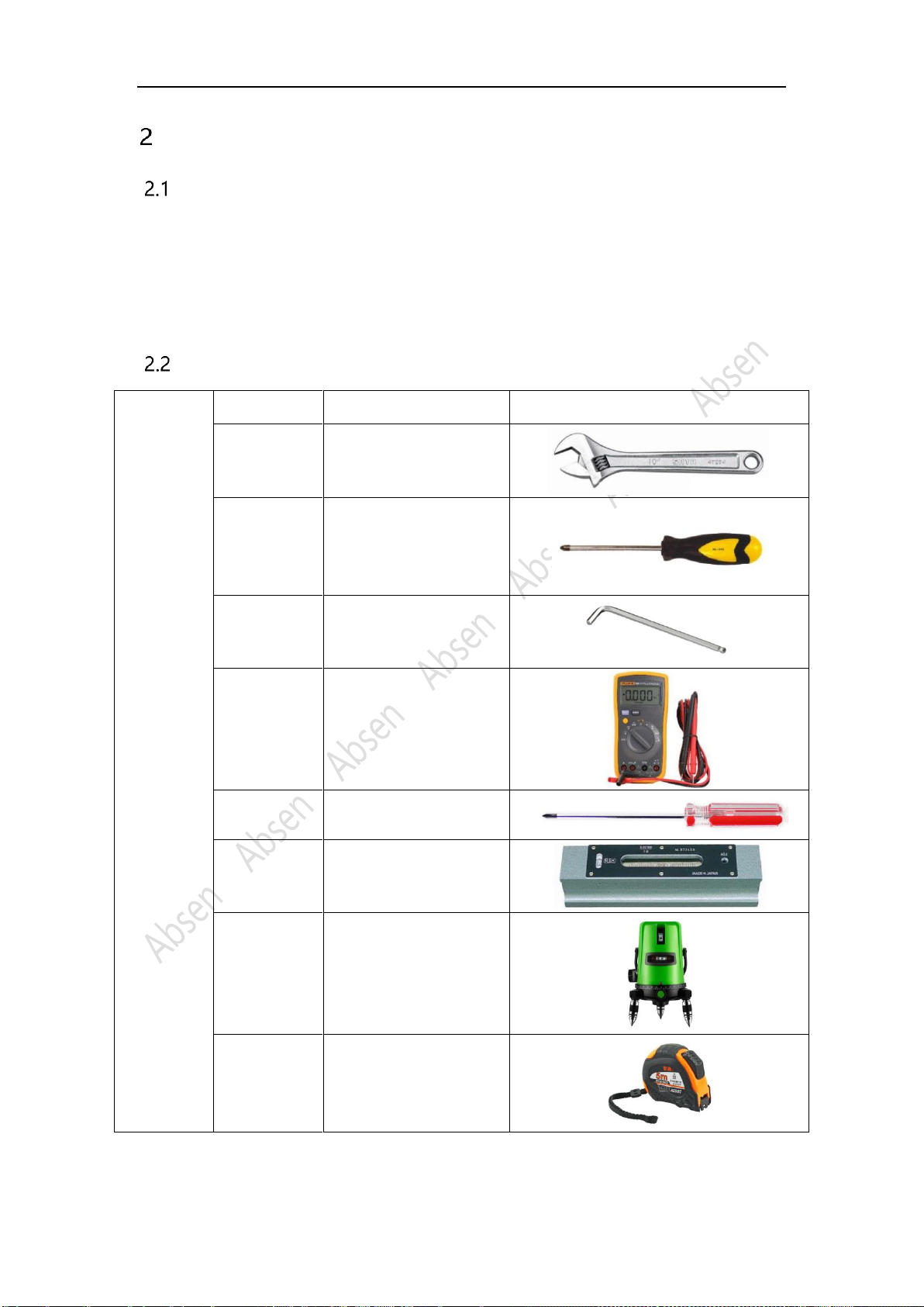
2Preparation before installation......................................................................................................................................- 5 -
2.1 Site installation environment preparation.................................................................................................- 5 -
2.2 Preparation of maintenance tools ...............................................................................................................- 5 -
3Product description ...........................................................................................................................................................- 6 -
3.1 Pictures of panels...............................................................................................................................................- 6 -
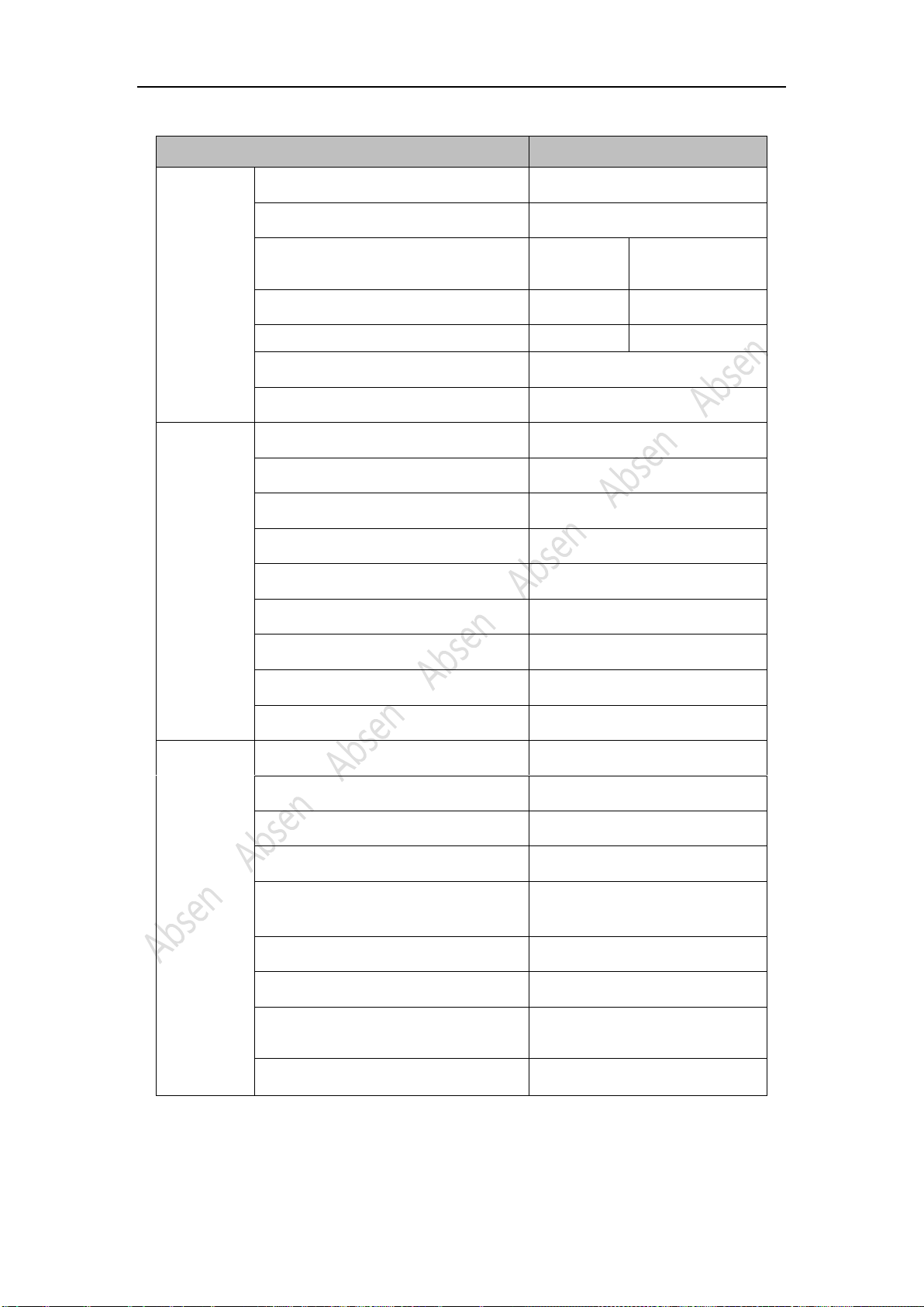
3.2 Product specifications.......................................................................................................................................- 7 -
3.3 Pictures of module.............................................................................................................................................- 9 -
3.4 Pictures of power: ........................................................................................................................................... - 10 -
3.5 Pictures of Receiving card:........................................................................................................................... - 10 -
3.6 Distribution box ............................................................................................................................................... - 11 -
3.7 Packing................................................................................................................................................................ - 12 -
4Installation procedure.................................................................................................................................................... - 13 -
4.1 Installation Notes: ........................................................................................................................................... - 13 -
4.2 Front-installation:............................................................................................................................................ - 13 -
5Cable connection............................................................................................................................................................. - 18 -
5.1 Cable connection ............................................................................................................................................ - 18 -
5.2 Load quantity of main power cable and main network cable........................................................ - 18 -
5.3 Post-installation inspection......................................................................................................................... - 18 -
5.4 Turn on the screen and see the performance...................................................................................... - 18 -
5.5 For software operation, please refer to the software instruction manual.................................. - 18 -
6Product maintenance..................................................................................................................................................... - 19 -
6.1 Module replacement ................................................................................................................................................ - 19 -
6.2 Common installation problems ............................................................................................................................ - 21 -
7Common installation issues ......................................................................................................................................... - 22 -
7.1 Large gap between the panels ............................................................................................................................. - 22 -
7.2 The panel cannot be fixed on the square tube (frame)............................................................................... - 22 -
7.3 Mask lifting and LED lamp knocking out .......................................................................................................... - 22 -
8Common faults and troubleshooting....................................................................................................................... - 23 -

Service hotline:400-700-3278
Safety information
The following marks on the product and in this manual indicate
important safety measures.
Warning: Be sure to learn and follow all safety guidelines, safety instructions, warnings and
precautions listed in this manual.
The use/operation of this product should be limited to professional technicians only! This product
may result in serious injury or death due to fire hazard, electric shock or hitting by falling items.
Please read this manual carefully before installing, powering, operating and
maintaining this product.
Follow safety instructions in this manual and on the product. If you have any
questions, please seek help from Absen.
WARNING!
Risk!
Might cause
equipment
damage or
risk!
WARNING!
Please read the
manual before
operating!
WARNING!
Dangerous
Voltage!
Might cause
equipment
damage or
electric shock!
WARNING!
Hot Surface!
Do not touch!
WARNING!
Flammable!
WARNING!
Possible
damage to eyes

Service hotline:400-700-3278
Beware of Electric Shock!
⚫To prevent electric shock the device must be properly grounded during
installation. Do not ignore using the grounding plug, or else there is a risk of
electric shock.
⚫During a lightning and thundering, please disconnect the device’s power
supply, or provide other suitable lightning protection. If the equipment is not
in use for a long time, please unplug the power cable.
⚫When performing any installation or maintenance work (e.g. removing the fuses, etc.,) make
sure you turn off the master/main switch.
⚫Disconnect AC power supply when the product is not in use, or before disassembling, or
installing the product.
⚫The AC power supply used in this product must comply with local building and electrical codes,
and should be equipped with overload and ground fault protection.
⚫The main power switch should be installed near the product and should be visible and easily
accessed. This way in case of any failure the power can be promptly disconnected.
⚫Before using this product check all electrical distribution equipment, cables and all connected
devices, and make sure all meet current requirements.
⚫Use appropriate power cables. Please select the appropriate power cables according to the
required power consumption and current capacity, and ensure the power cables are not
damaged, aged or wet. If any overheating occurs, replace power cables immediately.
⚫For any other questions, please consult professionals.
Beware of Fire!
⚫Use a circuit breaker or fuse protection to avoid fire caused by overloading
of power supply cables.
⚫Ensure good ventilation around the display, controller,
power supply and other devices, and keep a minimum 0.1meter gap
between these devices/objects.
⚫Do not stick or hang anything on the screen.
⚫Do not modify the product, do not add or remove parts.
⚫Do not use the product when the ambient temperature is over 50 ℃.

Service hotline:400-700-3278
Beware of Injury!
⚫Warning: Wear a helmet to avoid injury.
⚫Ensure any structures used to support, fix and connect the display can
withstand at least 10 times the weight of all the equipment.
⚫When stacking products, please hold products firmly to prevent tipping or
falling.
⚫Ensure all components and steel frames are securely and solidly installed.
⚫When installing, maintaining, or moving the product, ensure the working
area is isolated from other area, and ensure the working platform is securely
and stably fixed.
⚫In the absence of proper eye protection, please do not look directly at the
lit screen from within 1 meter.
⚫Do not use any optical devices that have converging functions to look at
the screen to avoid burning the eyes.
Warning: Beware of loads when hanging.
LED lamps used on the modules are sensitive and can be damaged by ESD
(electrostatic discharge). To prevent damage to LED lamps, do not touch
them when the device is running or switched off.
Warning: The manufacturer shall not bear any responsibility for any
incorrect, inappropriate, irresponsible or unsafe installation.

Service hotline:400-700-3278
Preparation before installation
Site installation environment preparation
1. Conventional panels cannot be installed on the seashore, and panels with special anti-salt-alkali
materials can be installed on the seashore
2. The humidity at the installation site must not exceed 85RH;
3. The installation site temperature should be -20 ℃ ~ 50 ℃, and the panels with special low temperature
materials can be installed at -30 ℃ ~ 20 ℃.
Preparation of maintenance tools
List
Type
Acting on
picture
Adjustable
wrench
Fix the connecting piece
of the box and tighten
the M10 * 60 bolt
Phillips
screwdriver
Disassembly module &
power supply &
receiving card & adaptor
plate
Hex key
Remove power box
multimeter
Measuring power lines
and distribution boxes
Small Phillips
screwdriver
Installing and removing
mask
Spirit level
Measuring structure
laser spirit
level
Measuring structure
band tape
Measuring structure

Service hotline:400-700-3278
Product description
Pictures of panels
Panel size: 500mm*500mm
Panel size: 750mm*500mm
Exploded Views

Service hotline:400-700-3278
Product specifications
AW2.8-Product specifications
Parameter
Specifications
Physical
parameters
LED type
SMD 3in1 1515
Pixel pitch (mm)
2.84
Panel size (width × height × thickness) /
(mm)
500*500
750*500
Panel resolution
176*176
264*176
panel weight(kg)
6.4
9.6
Panel material
Die-cast aluminum
Module size (width × height) / (mm)
250*250
Optical
parameters
Brightness (nit)
5000
Refresh frequency (Hz)
≥3840
Gray level (Bit)
14
Contrast
4500:1
Color temperature (K)
7000
Viewing angle (horizontal / vertical) (°)
160/125
Driving method
1/22
AC working voltage (V)
/
Power (Max / Average) (W / m2)
730/243
Application
parameters
Storage temperature (℃)
﹣40~﹢60
Operating temperature (℃)
-20~﹢50
Storage humidity (RH)
10%~85%
Operating humidity (RH)
10%~90%
Protection grade (front / rear)
IP65/IP54
LED life (H)
100000
Module maintenance method
Rear
Maintenance methods of power supply
& others
Rear
Installation method
Fixed installation (front/rear)
Note: The power will fluctuate within the range of ± 15%, depending on the brightness of
different batches of lamps, please refer to the actual product.

Service hotline:400-700-3278
AW3.9- Specifications
Parameter
Specifications
Physical
parameters
LED type
SMD 3in1 1921
Pixel pitch (mm)
3.9
Panel size (width × height × thickness) /
(mm)
500*500
750*500
Panel resolution
128*128
192*128
Panel weight(kg)
6.4
10
Panel material
Die-cast aluminum
Module size (width × height) / (mm)
250*250
Optical
parameters
Brightness (nit)
5000
Refresh frequency (Hz)
≥3840
Gray level (Bit)
16
Contrast
4500:1
Color temperature (K)
6500
Viewing angle (horizontal / vertical) (°)
160/130
Driving method
1/8
AC working voltage (V)
200~240
Power (Max / Average) (W / m2)
/
Physical
parameters
Storage temperature (℃)
﹣40~﹢60
Operating temperature (℃)
-20~﹢50
Storage humidity (RH)
10%~85%
Operating humidity (RH)
10%~90%
Protection grade (front / rear)
IP65/IP54
LED life (H)
100000
Module maintenance method
Rear
Maintenance methods of power supply
& others
Rear
Installation method
Fixed installation (front/rear)
Note: The power will fluctuate within the range of ± 15%, depending on the brightness of
different batches of lamps, please refer to the actual product.

Service hotline:400-700-3278
Pictures of module
AW modules are divided into 4 types,
A module and B module, used for normal standard panel;
C module and D module, used for rotating installation panel;
Adopt A module and B module, can be assembled into a normal standard panel.
Adopt C module and D module, can be assembled into a rotating installation panel;

Service hotline:400-700-3278
Pictures of power:
Power Specifications:
Parameter
Minimum value
Typical value
Maximum value
unit
Output voltage
range
4.2
4.6
4.6
VDC
Input voltage range
0
40A
A
Pictures of Receiving card:
Physical picture of receiving card
The A5S receiving card is connected to the Hub board through the card slot. Meanwhile, the Hub
board is also connected to the module, power supply and data cable. The Hub board plays the
role of transit.

Service hotline:400-700-3278
Distribution box
The distribution box is a low-voltage distribution box composed of switchgear, measuring
instruments, protective appliances and auxiliary devices, which are assembled in a closed or semi
closed metal cabinet or screen, based on the electrical wiring requirements.
During normal operation, the circuit can be switched on or off manually or automatically. The
measuring instruments show various parameters; some electrical parameters can be adjusted
through the measuring instruments; and they can indicate or send signals in case there is
deviation from normal working state.
The components in the power distribution box of the LED display mainly include: main switch,
AC contactor, circuit breaker (air switch), arrester (optional), timer, function card, time delay unit,
voltage indicator, current indicator, Thermal relay, e.tc
Classified by power capacity: Absen mainly has 15KW, 30KW, 60KW, 90KW, 120KW, 150KW,
180KW distribution boxes.
Classified by control mode: intelligent distribution box, ordinary distribution box.
Classified by application: indoor and outdoor.

Service hotline:400-700-3278
Distribution box and main cable selection
Distribution box specification
15KW
30KW
45KW
60KW
International copper core cable model(mm²)
4*4+1*2.5
4*10+1*6
4*16+1*10
4*25+1*16
Distribution box specification
90KW
120 KW
150 KW
180 KW
International copper core cable model(mm²)
4*50+1*35
4*70+1*35
4*95+1*50
4*120+1*70
Remark:
In the above table, the three-phase voltage is 380V and the single-phase voltage is 220V.
The input end of the distribution box is three-phase five-wire system, with a three-phase voltage of 380V
and a single-phase voltage of 220V at the output end.
4*X+1*X in the table: 4 represents L+L+L+N line, 1 represents PE line, X represents the main cable size;
If the single-phase voltage is 110V, then the international copper core cable model must be twice the size;
Packing
Wooden box + vacuum bag + anti-collision cotton
Voltmeter
voltmeter
Amperemeter
Stop light
Running light
Running Button
Stop button
Adjusting knob

Service hotline:400-700-3278
Installation procedure
Installation Notes:
The panel is waterproof front and rear, and can be directly installed naked. It can be installed
from front and rear. It cannot be installed directly against the wall.
When the panel is installed naked, there is no need for any covering on the edges or any other
decorations. The back of the panel is directly exposed outside, which relies on the external
environment for natural heat dissipation without other heat dissipation equipment.
When the back space of the panel is fully closed, heat dissipation equipment need to be installed
inside the closed space, such as air conditioner and exhaust fan, etc. About 1 air conditioner for
every 15 square meters screen.
The steel support structure of the panel must be designed and constructed in strict accordance
with our company's panel drawings. At least 60cm-80cm maintenance space should be reserved
for rear installation and 30-40cm for front installation.
During installation, the panel should be installed from the middle position at the bottom row of
the steel structure and installed from bottom to top. Fix the panel on the structure in turn with
connecting plates and M10x60mm bolts.
In order to facilitate the front maintenance of the power supply box, when the screen body is
used for front installation against the wall, a rear maintenance space of at least 25 cm must be
reserved in the sealed space on the back of the box.
Front-installation:
When front-installing the cabinet, it should be reserved at least 20cm on the back of the
cabinet. For facilitate subsequent after-sales service, please ensure that the rear-maintenance
space is not obscured.
1.Remove the module first;Use the front maintenance tool to insert into the front maintenance
hole of the module, rotate it counterclockwise then remove the module.
2.Place the panel on the horizontal frame of the steel structure, use 40*40 square tubes between
panels;
3.Pass the screws and connecting pieces through the space of the cabinet, and then tighten the
screws;
4.The box body and the square pass are fixed with connecting pieces;

Service hotline:400-700-3278
5.Fix the boxes with M8 * 30mm screws
Screw fixing position between left and right boxes
Screw fixing position between the upper and lower cases
Please pay attention to the fixing screws between the left and right boxes and the upper and
lower boxes during installation.
Left and right connection diagram M8 * 30 screws and nuts
6.Connected network cable and power supply;
Use the network cable output cable from the previous cabinet to pass through the network
cable jack of the next cabinet and connect to the HUB board;
7.Power on and test the power and network cables of the screen are plugged in well or not;
Before powering on, please test the power supply to ensure that the power cord is connected
correctly before you power on;

Service hotline:400-700-3278
8. Module installation
In order to avoid electric shock and damage to the module, it is necessary to install the module
according to the installation direction of the module.
4.3 Rear- installation
1、Place the two boxes side by side on the steel structure, and use the connecting piece to lock
the connection hole on the top of the box;
Mounting piece on the top of the cabinet
In order to avoid the dead light and the deformation of the box due to the collision of the box,
it needs to be handled gently when placing the box.

Service hotline:400-700-3278
When installing the cabinets, you need to check whether the cabinets are flat, whether there is a
front-to-back misalignment between the cabinets, or if the cabinets are misaligned, and
whether the cabinets are squeezed.
Rear-installation, the rear-maintenance space of the screen should be reserved at 60cm-80cm.
2、Installation of the bottom connection hole
3、Pass the left and right connection holes of the box with screws and lock with nuts;
Nut on the right side of the box Screws on the left side of the box M8 * 30 screws and nuts
4、Install the second row of cabinets, and then screw the upper and lower cabinets;
5、Continue to install other cabinets;

Service hotline:400-700-3278
6、Final renderings
Screw fixing position between left and right boxes
Screw fixing position between the upper and lower cases
Please pay attention to the fixing screws between the left & right boxes and the upper & lower
boxes when installing.
Left and right connection diagram M8 * 30 screws and nuts

Service hotline:400-700-3278
Cable connection
Cable connection
Plug the power and network cables on the left side of the back of the cabinet into the power
socket and network cable socket of the next cabinet. To avoid electric shock, please do not
power on when plugged in
Network cable connection Power cable connection
Load quantity of main power cable and main network cable
product model
1 pc main data cable can take:
(1 pc standard main data cable can carry
650,000 points; take the standard
1280*960*150 panel as an example)
1 pc standard main
Power cable can take:
(220V)
1 pc standard main
Power cable can take:
(110V)
AW2.8(500X500)
21pcs
20pcs
10pcs
AW2.8(750X500)
14pcs
13pcs
6pcs
AW3.9(500X500)
39pcs
23pcs
11pcs
AW3.9(750X500)
26pcs
16pcs
8pcs
Post-installation inspection
After the cabling between panels, use a multimeter to measure whether there is a short circuit at
the AC input (L/N/PE) and DC output (VCC/GND). If you find a short circuit, please check the
circuit carefully. Make sure the circuits and cables are all right before powering the display and
turning it on. Pay attention to the working voltage range of the panel when turning on the display
to avoid the whole screen burning out due to the wrong working voltage.
Turn on the screen and see the performance
When the screen is powered on, play high-definition content, such as video, text, images, etc.
It is suggested to make sure the resolution of the content consistent with the resolution of the
screen, otherwise the content will be compressed, thus affecting the overall performance.
For software operation, please refer to the software instruction
manual.
This manual suits for next models
2
Table of contents
Popular Industrial Monitor manuals by other brands

Advantech
Advantech FPM-7211W Series user manual

VarTech Systems
VarTech Systems VT150CC user guide

Crystal Image
Crystal Image RMPW-161-19 user manual

Total Controls
Total Controls QuickPanel jr. QPKSxDN0000 Series installation instructions

Lika
Lika Posicontrol IF55 LIN CB Series manual

Advantech
Advantech IDS31-320W user manual