Absen LR3.9-7.8 User manual

LR3.9-7.8 User Manual
High transparency
Lightweight
Fast operation
Curved design
High refresh
rate

- 2 - LR3.9-7.8 User Manual
Catalogue
Safety Information............................................................................................................................................... - 3 -
1.Product Introduction......................................................................................................................................- 5 -
1.1Product Main Features........................................................................................................................- 5 -
1.2Product Specifications.........................................................................................................................- 6 -
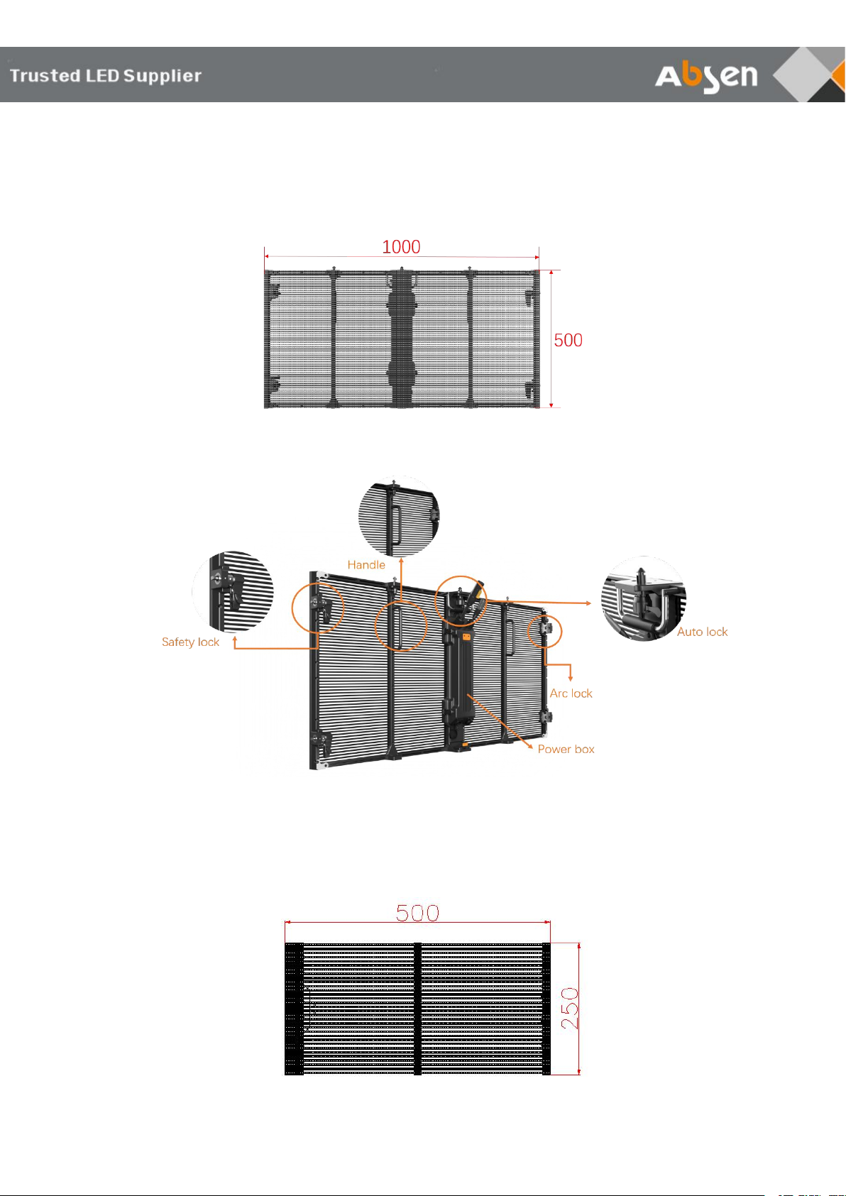
1.3Cabinet.................................................................................................................................................. - 7 -
1.3.1 Cabinet dimension figure.......................................................................................................- 7 -
1.3.2 Cabinet structure description................................................................................................ - 7 -
1.4Module................................................................................................................................................... - 7 -
1.4.1 Module dimension figure....................................................................................................... - 7 -
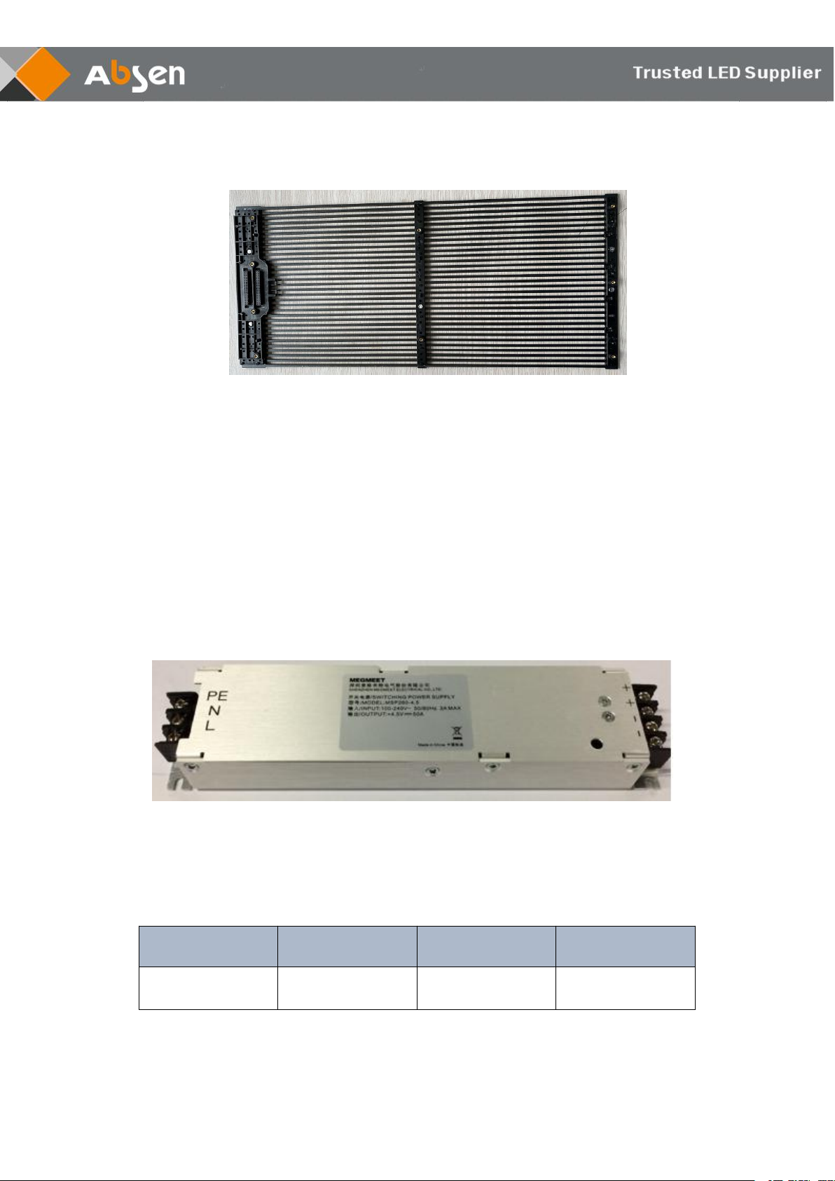
1.4.2 Features of Module................................................................................................................ - 8 -
1.5Power Supply........................................................................................................................................- 8 -
1.5.1 Power Output characteristics............................................................................................... - 8 -
1.5.2 Power Input characteristics.................................................................................................. - 9 -
1.6Receive Card........................................................................................................................................ - 9 -
2.Product Installation..................................................................................................................................... - 10 -
2.1 Preparation Before Installation........................................................................................................- 10 -
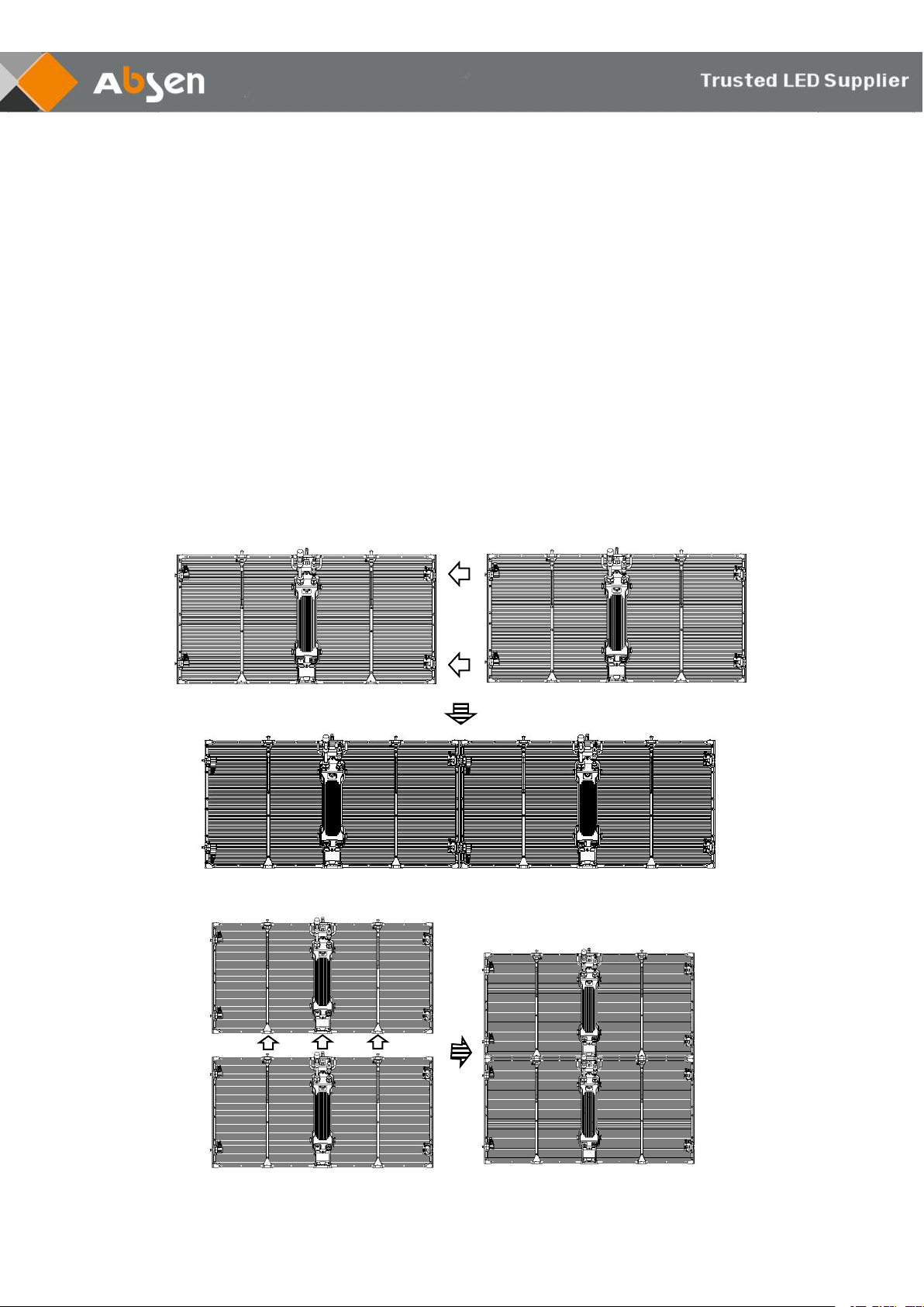
2.2 Cabinets Splicing...............................................................................................................................- 10 -
2.2.1 Splicing horizontally............................................................................................................. - 10 -
2.2.2 Splicing vertically.................................................................................................................. - 10 -
2.2.4 90-degree Splicing............................................................................................................... - 11 -
2.2 Hanging Installation.......................................................................................................................... - 12 -
2.2.1 Preparation for hanging installation................................................................................... - 12 -
2.2.2 Hanging installation steps................................................................................................... - 12 -
2.3 Fixed Installation............................................................................................................................... - 15 -
2.3.1 Preparation for fixed installation.........................................................................................- 15 -
2.3.2 Fixed installation steps........................................................................................................ - 15 -
3.Product Cabling...........................................................................................................................................- 17 -
3.1 Attention of Cabling...........................................................................................................................- 17 -
3.2 Wring Diagram...................................................................................................................................- 18 -
4.Maintenance................................................................................................................................................ - 18 -
4.1 Preparation of Maintenance Tools..................................................................................................- 18 -
4.2 Module Maintenance........................................................................................................................ - 19 -
4.2.1 Module maintenance steps................................................................................................. - 19 -
4.3 Power Supply Maintenance.............................................................................................................- 20 -
4.3.1 Power supply maintenance steps...................................................................................... - 20 -
4.4 Receive Card Maintenance............................................................................................................. - 21 -
4.4.1 Receive card maintenance steps.......................................................................................- 21 -
4.5 Hub Maintenance.............................................................................................................................. - 22 -
5. Flight Case.....................................................................................................................................................- 22 -
6. Common Faults and troubleshooting.........................................................................................................- 23 -

- 3 - LR3.9-7.8 User Manual
Safety Information
The following marks on the product and in this manual indicate important safety
measures.
WARNING: Be sure to understand and follow all safety guidelines, safety instructions, warnings
and precautions listed in this manual. This product is for professional use only!
This product may result in serious injury or death due to fire hazard, electric shock, and
crushing hazard.
Please read this manual carefully before installing, powering up, operating and maintenance of
this product. Follow safety instructions in this manual and on the product. If you have any
questions, please seek help from Absen.
Beware of Electric Shock!
• To prevent electric shock the device must be properly grounded during installation. Do not
ignore using the grounding plug, or else there is a risk of electric shock.
• During a lightning storm, please disconnect the device’s power supply, or provide other suitable
lightning protection. If the equipment is not in use for a long time, please unplug the power cord.
• When performing any installation or maintenance work (e.g. removing the fuses, etc.,) make
sure to turn off the master switch.
• Disconnect AC power when the product is not in use, or before disassembling, or installing the
product.
• The AC power used in this product must comply with local building and electrical codes, and
should be equipped with overload and ground fault protection.
• The main power switch should be installed at a location near the product and should be clearly
visible and easily reached. This way in case of any failure the power can be promptly
disconnected.
• Before using this product check all electrical distribution equipment, cables and all connected
devices, and make sure all meet current requirements.
• Use appropriate power cords. Please select the appropriate power cord according to the
required power and current capacity, and ensure the power cord is not damaged, aged or wet. If
any overheating occurs, replace power cord immediately.

- 4 - LR3.9-7.8 User Manual
• For any other questions, please consult a professional.
Beware of Fire!
• Use a circuit breaker or fuse protection to avoid fire caused by power supply cables
overloading.
• Maintain good ventilation around the display screen, controller, power supply and other
devices, and keep a minimum 0.1 meter gap with other objects.
• Do not stick or hang anything on the screen.
• Do not modify the product, do not add or remove parts.
• Do not use the product in case ambient temperature is over 55 ℃.
Beware of Injury!
• Warning: Wear a helmet to avoid injury.
• Ensure any structures used to support, fix and connect the equipment can withstand at least
10 times the weight of all the equipment.
• When stacking products, please hold products firmly to prevent tipping or falling.
• Ensure all components and steel frames are securely installed.
• When installing, repairing, or moving the product, ensure the working area is free of obstacles,
and ensure the working platform is securely and stably fixed.
• In the absence of proper eye protection, please do not look directly at the lit screen from within
a 1 meter distance.
• Do not use any optical devices that have converging functions to look at the screen to avoid
burning the eyes.
WARNING: Beware of suspended loads.
LED lamps used in the module are sensitive and can be damaged by ESD (electrostatic
discharge). To prevent damage to LED lamps, do not touch when the device is running or
switched off.
WARNING: The manufacturer shall not bear any responsibility for any incorrect, inappropriate,
irresponsible or unsafe system installation.
Product Disposal
• Any component that has a recycling bin label can be recycled.
• For more information on collecting, reusing and recycling, please contact the local or regional
waste management unit.
• Please contact us directly for detailed environmental performance information.

- 5 - LR3.9-7.8 User Manual
1.Product Introduction
LR3.9-7.8 is a transparent LED display screen specially designed for stage rental use.
LR3.9-7.8 uses die-casting aluminum structure and LED curtain with more than 50%
transparency, greatly reducing wind resistance and better cooling effect. The cabinet
dimension is 1000*500mm, and its weight is no more than 6kg.
The product is primarily used at live music in order to create mysterious stage effect and
as a medium for video broadcast, information transmission, and so on.
1.1 Product Main Features
• The transparency of LR3.9-7.8 is as high as 50%, which can create a mysterious stage
effect.
• LR3.9-7.8 has thin panel and hollowed-out PCB, which can bring the advantage of light
weight, making operation and movement more convenient. One panel’s weight is no more
than 6kg.
• The advanced lock system with safety mechanism makes the installation firmer, and
the two-handle design makes the operation faster.
• LR3.9-7.8 has curve connection blocks, which are available to support curve from -15
degree to +15 degree, giving users unlimited design flexibility of flat, concave and convex
screen. Meanwhile, LR3.9-7.8 can also offer 90 degree splicing screens, and support
splicing with the curve screen to make creative design.
• LR3.9-7.8 supports high refresh rate, which can quickly achieve dynamic response to
prevent vivid display performance whereas the product with low refresh rate resulted in
low-quality display performance and scanning lines when photos taken.
• LR3.9-7.8 is available for both hanging installation and fixed installation, for more
efficient space utilization for customers.

- 6 - LR3.9-7.8 User Manual
1.2 Product Specifications
Remark: Power consumption tolerance: ±15%, according to the actual situation.
Parameters
LR3.9-7.8
Physical
Parameters
LED Type
SMD1921
Pixel Pitch (mm)
Horizontal 3.9 - Vertical 7.8
Cabinet Pixels
256*64
Pixel Density (Pixels / m2)
34544
Module size (L × W)/(mm)
500*250
Panel size (L × W × H)/(mm)
1000*500*77.2
Cabinet Material
Die-cast Aluminum
Cabinet Weight (㎏/Cabinet)
6
Grayscale
14
Refresh Rate (Hz)
3840
Drive Mode
1/16
Signal Transmission Distance (m)
UTP cable:<100 m; Single-mode fiber:<10 km
Optical
Parameters
Brightness (nit)
2500
Viewing Angle (H/V)(°)
160/150
Electrical
Parameters
AC Input Voltage (V)
100~240
Power Consumption
(Max/Avg.)(W/m2)
335/112
Environment
al Parameters
Storage Temperature (˚C)
-40~+60
Working Temperature (˚C)
-20~+50
Storage Temperature (RH)
10%~90%
Working Humidity (RH)
10%~90%
Ingress Protection
IP65/IP54
Product Life (hrs)
100000
Leasing
Product
Installation
Panel Installation Method
Hanging/Fixed
Maximum number of hoisted
cabinets
20

- 7 - LR3.9-7.8 User Manual
1.3 Cabinet
1.3.1 Cabinet dimension figure
1.3.2 Cabinet structure description
1.4 Module
1.4.1 Module dimension figure

- 8 - LR3.9-7.8 User Manual
1.4.2 Features of Module
• A cabinet consists of 4 modules, and each module is fixed by 9 screws.
• After removing the fixing screws on the power box adapter and the box frame to
remove the module.
• Industrial-grade waterproof socket to make more stable, and the fast elastic plug which
can make usage and maintenance more convenience.
1.5 Power Supply
1.5.1 Power Output characteristics
Output Voltage
Regulation
Min. Current
Rated Current
+4.5V
±5%
0A
50A

- 9 - LR3.9-7.8 User Manual
1.5.2 Power Input characteristics
Input Voltage Range
90Vac to 264Vac
Normal Voltage Range
100Vac to 240Vac
Frequency Range
47Hz-63Hz
Max Input AC Current
3.5Amax. at full load condition
Inrush Current ( cold state )
60A typ. Peak@230Vac
Efficiency (full load )
89%@220VAac
Leakage Current
Less than 3.5 mA,
@ 240Vac input
Normal Output Power
250W
Input Fuse
T5AH/250Vac
Power Factor
>0.95@ full Load 220Vac input
( Universal AC Input With Active
PFC )
1.6 Receive Card
The A5S receiving card is connected to the Hub board through the card slot. Meanwhile,
the Hub board which plays the role of transit is also connected to the module, power supply
and data cable.

- 10 - LR3.9-7.8 User Manual
2.Product Installation
2.1 Preparation Before Installation
• Conventional panels cannot be installed on the seashore, and panels with special
anti-salt-alkali materials can be installed on the seashore
• The humidity at the installation site must not exceed 85RH;
• The installation site temperature should be -20 ℃~ 50 ℃, and the panels with
special low temperature materials can be installed at -30 ℃~ 20 ℃.
2.2 Cabinets Splicing
2.2.1 Splicing horizontally
2.2.2 Splicing vertically

- 11 - LR3.9-7.8 User Manual
2.2.3 Curve and Convex Splicing
Note: LR3.9-7.8 supports curve form -15 degree to +15 degree by adjusting the arc lock to
create multiple splicing effect.
2.2.4 90-degree Splicing
Note: 90-degree splicing screen fixed by right angle connector.

- 12 - LR3.9-7.8 User Manual
2.2 Hanging Installation
2.2.1 Preparation for hanging installation
Note: 1000mm single hanging bar is used for hanging installation
2.2.2 Hanging installation steps
Step 1, Fix the hanging bars on the truss with wire rope, and connect the hanging bars
horizontally with block.
Step 2, Use the vertical connectors to fix the first row cabinets to the locking tabs of the
hanging bars.
cliver
Locking tabs
Vertical connectors

- 13 - LR3.9-7.8 User Manual
Step 3, Splicing the first row cabinets horizontally: First, adjust the angle of the arc lock
and fix it; Then, align the connection holes of the left and right cabinets; After that, push
the bolt of the horizontal connector into the hole; Last, fasten the bolt by turning it down.
Step 4, Install other cabinets from top to bottom: First, align the connection holes of upper
and lower cabinet; Then, let the connector tab to the left; After that, push the bolt of the
vertical connector into the hole; Last, fasten the connector by turning its tab to right.
Align the holes
Adjust the angle of the arc lock
Push the bolt and turn it down
Fasten the connector

- 14 - LR3.9-7.8 User Manual
Step 5, Connect the power cables and the network cables between the cabinets.
Note: Maximum number of installations: 20
Align the holes
Let the tab to the right
Push the bolt and turn its tab to the right

- 15 - LR3.9-7.8 User Manual
2.3 Fixed Installation
2.3.1 Preparation for fixed installation
Note: Absen only offer connector block and connector plates for fixed installation if
customer needs.
2.3.2 Fixed installation steps
Step 1, Fixing the cabinets by connector block.
Step 2, Connect the cabinets to the steel structure by connector plates.
( Please watch the installation video for details )

- 16 - LR3.9-7.8 User Manual
Connector plate
Connector block
40*40Steel structure

- 17 - LR3.9-7.8 User Manual
3.Product Cabling
3.1 Attention of Cabling
LR series network cables and power cables are connected by aviation heads, as above:
Note: The connecting cables between the cabinets should pass through the cabinets as
much as possible. If the connection method changed, please set the same connection
method in the software settings. Please refer to the software for more details.
Note:
1. Load capacity of main power cable and main network cable.
2. Checking.
After the cabinet wiring is completed, use a multimeter to measure whether there is a
short circuit between the AC input (L / N / PE) and DC output (VCC / GND) of the power
supply. If so, please check the wiring carefully. Please make sure the circuit is normal
before power on. To avoid the entire screen being burned due to the wrong working
voltage, please pay attention to the working voltage range of the cabinet when use.
3. Turn on the screen and check the effect.
When the screen is powered on, play high-definition content, such as video, text, images,
etc. It is suggested to make sure the resolution of the content consistent with the
resolution of the screen, otherwise the content will be compressed, thus affecting the
overall performance.
4. For software operation, please refer to the software instruction manual.
Power cable routing: Details of the loaded box: When 220V power supply, a single power
line can load up to 16 cabinets, and when 110V power supply, a single power line can load
up to 8 cabinets.
Network cable routing: The signal cables are connected from left to right. Please calculate
the resolution according to the pixels of each cabinet. Note that the maximum load of a
single network port does not exceed 650,000 pixels.

- 18 - LR3.9-7.8 User Manual
3.2 Wring Diagram
4.Maintenance
4.1 Preparation of Maintenance Tools
List
Type
Function
Picture
Adjustable
wrench
Fix the connecting piece
of the box and tighten
the M10 * 60 bolt
Phillips
screwdriver
Disassembly module &
power supply &
receiving card & adaptor
plate
multimeter
Measuring power lines
and distribution boxes

- 19 - LR3.9-7.8 User Manual
Small Phillips
screwdriver
Installing and removing
mask
Spirit level
Measuring structure
laser spirit
level
Measuring structure
band tape
Measuring structure
4.2 Module Maintenance
The modules of LR3.9-7.8 support rear maintenance only.
4.2.1 Module maintenance steps
Step 1, Remove power box from panel by loosening four buckles.
Step 2, Loosen the fixing screws of the module with a cross screwdriver, then take out the
module from panel.

- 20 - LR3.9-7.8 User Manual
Note:
1. Each module is fixed by 9 screws.
2. When the socket on the module is relatively tight with the adapter board, you can use a
flat-blade screwdriver to slightly pry the contact position between the module and the
adapter board. To avoid module damage, please pay attention to force evenly when
remove the module.
4.3 Power Supply Maintenance
The power supply of LR3.9-7.8 supports rear maintenance only.
4.3.1 Power supply maintenance steps
Step 1, Open the four buckles of the power box.
Step 2, Place the power supply horizontally and open the cover.
Table of contents
Other Absen Projection Screen manuals
Popular Projection Screen manuals by other brands

Cirrus Screens
Cirrus Screens Stratus Series user manual

Grandview
Grandview CR-Pxx instruction manual

Elite Screens
Elite Screens TE100HC2 user guide

Akia Screens
Akia Screens EDGE FREE CLR 2 Series user guide

Elite Screens
Elite Screens Elite Home Series user guide

Screen Research
Screen Research MMS2-L1 installation manual