Subject to alteration without prior notice.
2
US_CA/ A•mist_10C/UM2239-1
BASIC INFORMATION
1.1 INTRODUCTION
This manual contains all necessary information
about safety, commissioning and maintenance.
For more information regarding installation, please
see separate installation manual.
This product is produced and designed in accor-
dance with applicable EC directives.
To preserve this status, this unit must be installed,
repaired and maintained by skilled personnel and
genuine spare parts must be used.
For advice when technical service or spare parts are
needed, contact Absolent or your nearest authori-
zed dealer. You will nd details on who to contact
under the heading: ”Technical Support”.
1.2 RANGE OF APPLICATION
The A•mist10C lter unit is designed for cleaning air
containing oil mist* only.
Use of the lter unit for other applications is not
permissible, unless the manufacturer guarantees
its proper function. If the A·mist lter unit is used
in applications where there are traces of graphite,
lead or chrome, you might need to clean or change
lter cassettes more often.
* From cutting uids like emulsion, synthetical oil or/and mi-
neral oil.
1.3 CONTENTS CONT’D.:
5 OPERATION / DESIGN ..................................... 5
5.1 Function A•mist10C ............................................ 5
5.2 Function A•mist10C HEPA................................. 5
6 TECHNICAL DATA ............................................. 6
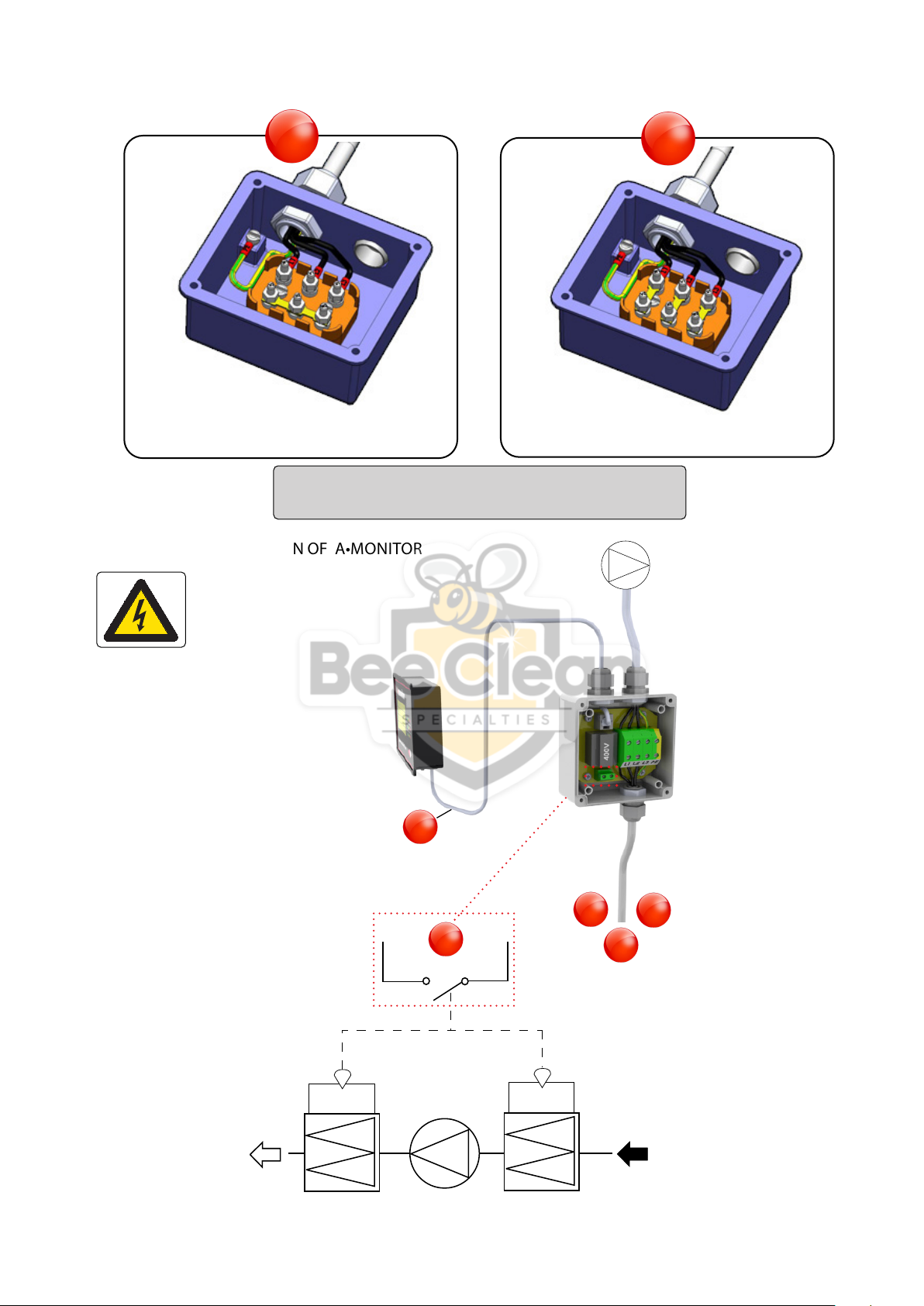
7 ELECTRICAL CONNECTIONS ........................ 6
7.1 General................................................................. 6
7.2 Electrical connection of the fan motor
for direct start .................................................. 7
7.3 Electrical connection of A•monitor............ 7
8 STARTING THE FILTER UNIT FOR THE ...........
FIRST TIME .......................................................... 8
9 CARE/MAINTENANCE .................................... 8
9.1 General................................................................. 8
9.2 Service Schedule............................................... 8
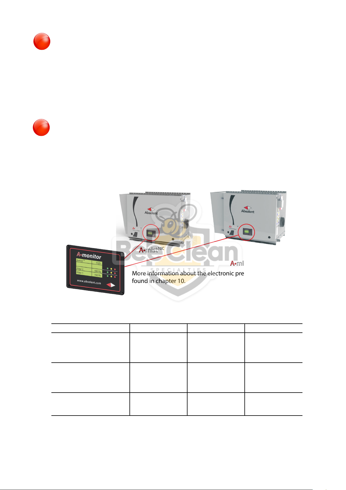
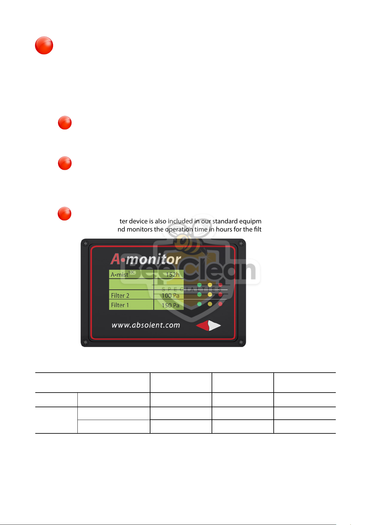
10 ELECTRONIC PRESSURE MANOMETER...... 9
10.1 Function description....................................... 9
10.2
Pressure settings electronic manometer
... 9
11 HANDLING THE FILTER CASSETTES..........10
11.1 General...............................................................10
11.2 Filter cassette positioning ...........................10
11.3 Instructions for replacing lter
stage 1 ...............................................................11
11.4 Instructions for replacing HEPA lter ......12
11.5 Worn out lter cassettes .............................13
11.6 To clean lter cassettes ................................13
12 ACCESSORIES ...................................................14
12.1 Wall mounting bracket.................................14
12.2 Ceiling hung.....................................................14
12.3 Floor stand........................................................14
12.4 Outlet duct connection................................14
12.5 Liquid trap options ........................................15
12.5.1 Liquid trap - hose............................................15
12.5.2 Liquid trap - PVC .............................................15
12.5.3 Liquid trap - steel bucket.............................15
12.5.4 Liquid trap - receptacle ................................15
12.6 Extension hood for after-assembly of
HEPA....................................................................16
12.7 Spray system ....................................................16
12.8 Motor protection............................................16
12.9 Frequency converter.....................................16
13 FAULT TRACING................................................17
14 CHECKING THE FAN’S DIRECTION OF
ROTATION ..........................................................18
15 ABSOLENT WARRANTIES..............................18
16 SPARE PARTS.....................................................19
17 TECHNICAL SUPPORT....................................19
18 EC DECLARATION OF CONFORMITY ........20
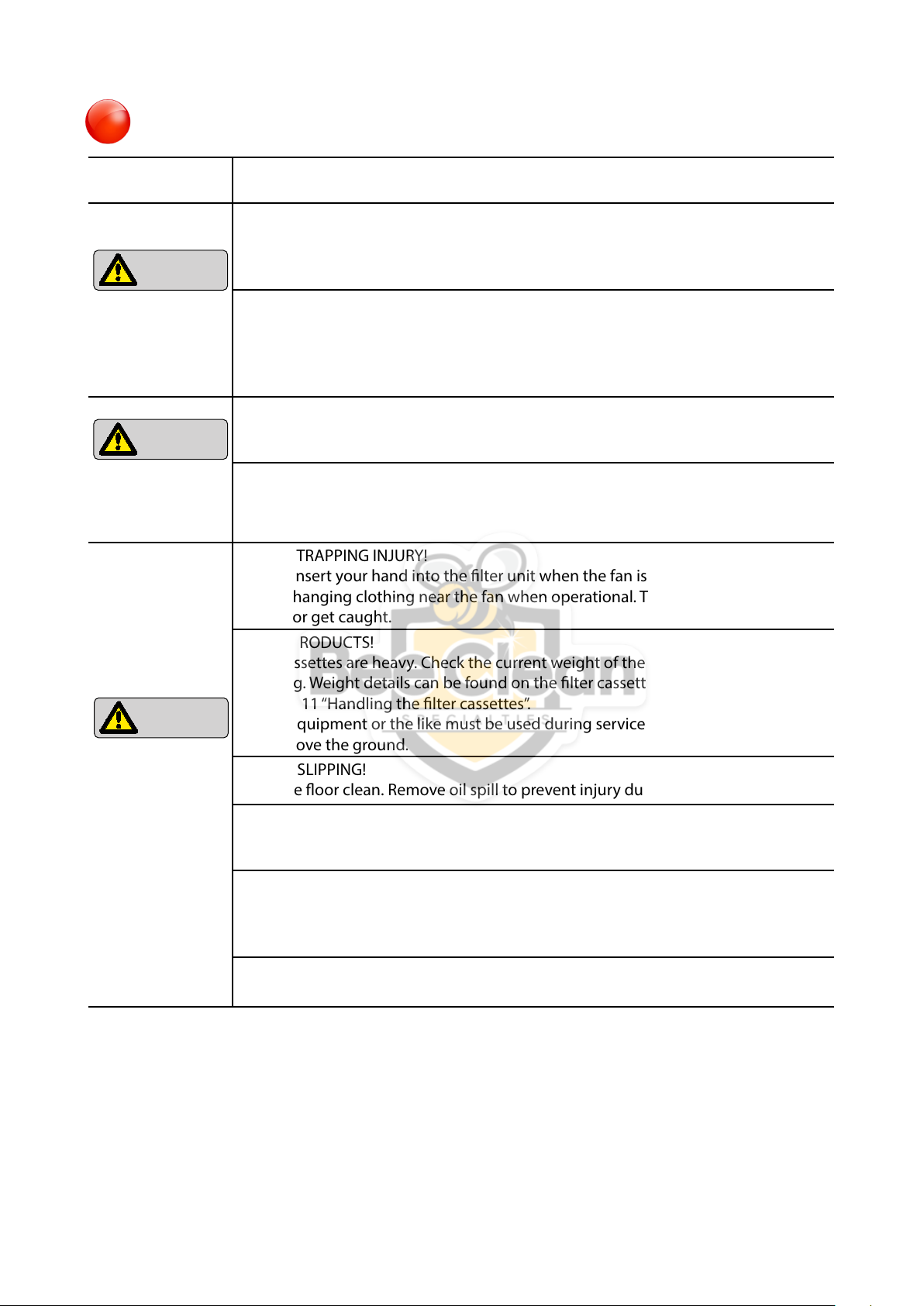
Read and understand the user’s
manual before beginning work in
the lter unit.
1
1.3 CONTENTS:
1 BASIC INFORMATION......................................... 2
1.1 Introduction ......................................................... 2
1.2 Range of Application......................................... 2
1.3 Contents................................................................. 2
2 APPROVED TO CE DIRECTIVES,
UL AND CSA STANDARDS................................ 3
3 LIST - WARNING SIGNS...................................... 3
4 SAFETY PRECAUTIONS...................................... 4