2
EN/US/CA/A.mist A.mistT/UM-2239-1
Subject to alteration without prior notice.
1.1 Introduction
This manual contains all necessary information
about safety, installation, commissioning and
maintenance.
This product is produced and designed in ac-
cordance with applicable EC directives.
To preserve this status, this unit must be instal-
led, repaired and maintained by skilled person-
nel and genuine spare parts must be used.
For advice when technical service or spare
parts are needed, contact Absolent or your
nearest authorized dealer. You will nd details
on who to contact under the heading: ”Technical
Support”.
1.2 Range of Application
The A•mist lter unit is designed for cleaning air
containing oil mist* only. Use of the lter unit for
other applications is not permissible, unless the
manufacturer guarantees its proper function.
If the A•mist lter unit is used in applications
where there are traces of graphite, lead or ch-
rome, you might need to clean or change lter
cassettes more often.
* From cutting uids like emulsion, synthetical oil or/and
mineral oil.
BASIC INFORMATION
1
1.3 List of contents, continued:
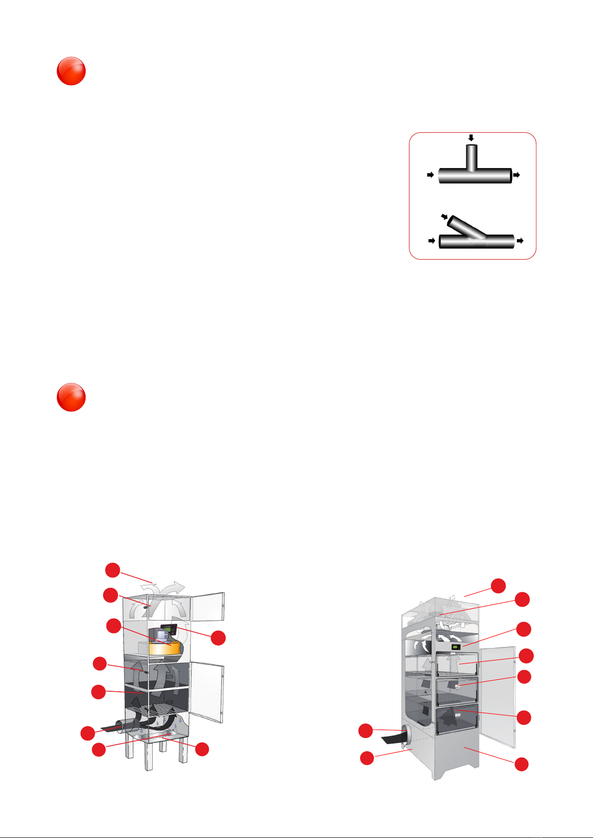
5 Transport at site/Mounting/
Installation ......................................5
5.1 General.............................................5
5.2 Transporting A•mist6C, A•mist10,
A•mist20 .............................................5
5.3 Transporting A•mist60 ........................5
5.4 Transporting A•mist40-80 .....................6
5.5 Floor mounting..................................6
5.6 Installation.........................................7
6 Operation / Design .........................7
7 Technical Data.................................8
7.1 Technical data A•mist6C, A•mist10, .......
A•mist20, A•mist60...............................8
7.2 Technical data A•mist40T/TF .................9
7.3 Technical data A•mist80T/TF ...............10
8 Electrical Connections ................ 11
8.1 General........................................... 11
8.2 Wiring the Motor for Direct Online
Starting ......................................... 11
8.3 Electrical connection of A•monitor ..12
9 To be checked before the rst
start of the lter unit ....................13
10 Care / Maintenance .....................13
10.1 General...........................................13
10.2 Service Schedule............................14
11 Electronic manometer..................15
11.1 Functional description.....................15
11.2 Pressure settings............................15
12 Handling the Filter Cassettes .....16
12.1 General...........................................16
12.2 Instructions for Replacing Filter
Cassettes........................................16
12.3 Worn Out Filter Cassettes ..............17
12.4 To Clean Filter Cassettes................17
12.5 Not cleanable Filter Cassettes........17
13 Accessories...................................18
13.1 Liquid Traps ....................................18
13.2 Extension Legs ...............................19
13.3 Dierent hoods ...............................19
13.4 Spray System .................................20
13.5 Carbon Filter Cassette....................20
13.6 Motor Protection .............................20
13.7 Frequency Converter......................20
13.8 Prelter for severe dirt ....................21
13.9 Stand-alone A•monitor....................21
14 Fault Tracing .................................22
15 Absolent warranties .....................23
16 Spare Parts....................................23
17 Technical Support.........................23
18 EC Declaration of conformity ......24
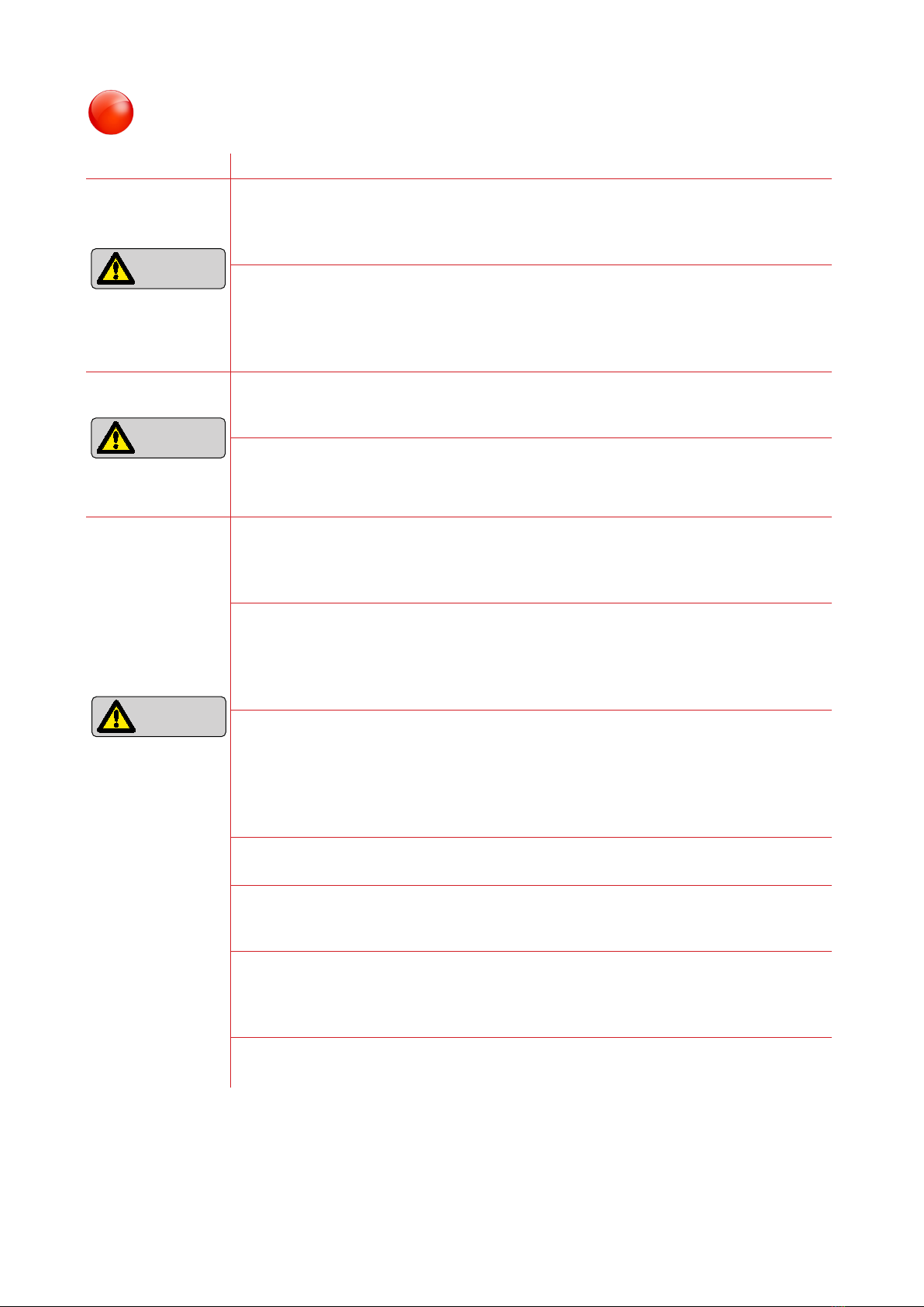
Read and understand the
user’s manual before begin-
ning work in the lter unit.
1.3 Table of contents:
1 Basic information ...........................2
1.1 Introduction.......................................2
1.2 Range of Application.........................2
1.3 List of contents..................................2
2 Approved to CE-directives, UL and
CSA standards ................................3
3 List of Warning Signs.....................3
4 Safety Precautions .........................4