Installation and Setup API 1400 G, API 1420 G
Precautions
WARNING! All wiring must be performed by a qualified electrician
or instrumentation engineer. See diagram for terminal designa-
tions and wiring examples. Consult factory for assistance.
WARNING! Avoid shock hazards! Turn signal input, output, and
power off before connecting or disconnecting wiring, or remov-
ing or installing module.
Précautions
ATTENTION! Tout le câblage doit être effectué par un élec-
tricien ou ingénieur en instrumentation qualifié. Voir le dia-
gramme pour désignations des bornes et des exemples de
câblage. Consulter l’usine pour assistance.
ATTENTION! Éviter les risques de choc! Fermez le signal
d’entrée, le signal de sortie et l’alimentation électrique avant
de connecter ou de déconnecter le câblage, ou de retirer ou
d’installer le module.
Alarm Configuration
API 1400 G relay operation is factory configured. The default
configuration is HI alarm normal acting. See model/serial num-
ber label for optional relay configurations.
API 1420 G relay operation is factory configured, but internal
jumpers can be used to modify the alarm type as follows.
1. Unplug the module from the socket.
2. Remove the 4 screws from the module bottom and remove
the plastic case.
3. Unplug the circuit board with the test button from the base.
4. Note location of jumper block at top left of circuit board next
to test button. See diagram at right.
5. Place jumpers as indicated for desired alarm operation.
The standard HI/LO setting is with one jumper across the
two top pins or with no jumper at all. Never place a jumper
across the two bottom pins!
6. Replace board, cover, and screws.
Socket and Mounting
Install module in a protective panel or enclosure. Allow space
around module for air flow. Use API 011 or API 011 FS socket.
See specifications for maximum allowable socket voltages. The
socket clips to a standard 35 mm DIN rail or can be mounted to
a flat surface.
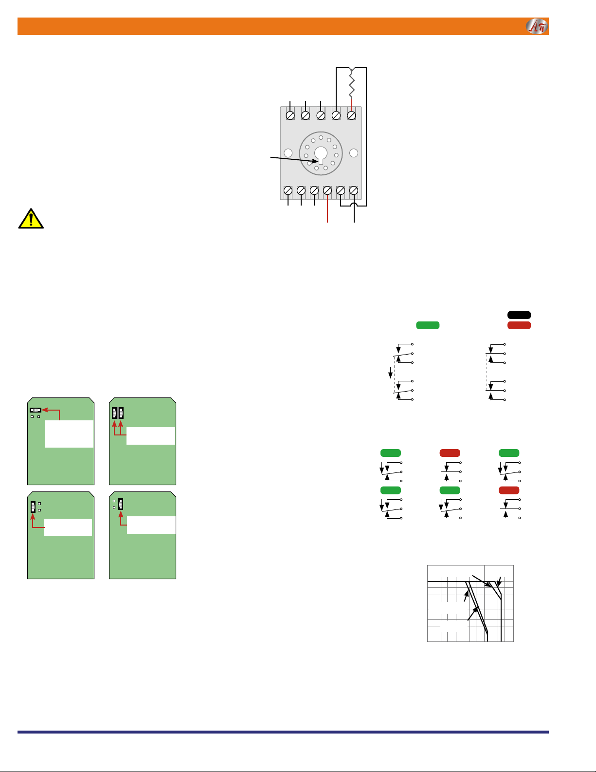
Input
The input is factory configured (at 24°C ±1°C). See the model/
serial number label for input type, range, and options.
Correct wiring of 3-wire RTDs must be observed.
Connect 2-wire sensors to terminals 4 and 5 and run a jumper
wire from terminal 2 to 5.
Relay Output
See wiring diagram for connections. The module does not
provide power to the relay contacts.
Inductive loads (motors, solenoids, contactors, etc.) will greatly
shorten relay contact life unless an appropriate RC snubber
is installed.
Module Power
Check model/serial number label for module operating voltage
to make sure it matches available power.
When using DC power, polarity must be observed. The positive
(+) must be wired to terminal 1 and negative (–) must be wired
to terminal 3.
Setpoint
This multi-turn potentiometer (one for each setpoint on the API
1420 G) allows the operator to adjust the level at which the
alarm is activated. This control is adjustable from 0 to 100%
of the input range.
Deadband
The API 1400 G deadband potentiometer allows the alarm trip/
reset window to be adjusted symmetrically about the setpoint
from 1 to 100% of the span.
The deadband is fixed at 1% of span on the API 1420 G. The API
1420 G A with adjustable deadband option allows deadbands
to be adjusted symmetrically about each setpoint from 1 to
100% of the span.
Deadband allows the operator to fine tune the point at which
the alarm trips and resets. The deadband is typically used to
prevent chattering of the relays or false trips when the process
signal is unstable or changes rapidly.
Adjustments
To calibrate the alarm section, set the deadband control to the
minimum (counterclockwise). The deadband will be 1.0% of
input span in this case.
Set the signal source to a reference that represents the desired
trip point.
Adjust the setpoint control to the point at which the relay
changes state from a non-alarm to an alarm condition.
If a larger amount of deadband is desired turn the deadband
potentiometer clockwise. The deadband is symmetrical about
the setpoint; both transition points will change as deadband
is increased.
Alternately set the setpoint and deadband until the desired trip/
reset points are set.
Output Test Function
The functional test button toggles the alarm status independent
of the input when depressed. It verifies the alarm and system
operation. When released, the relay(s) will return to their prior
states. This can be used as a diagnostic aid during initial start-
up or troubleshooting.
Operation
The green LoopTracker®input LED provides a visual indication
that a signal is being sensed by the input circuitry of the mod-
ule. It also indicates the input signal strength by changing in
intensity as the process changes from minimum to maximum.
If the LED fails to illuminate, or fails to change in intensity as
the process changes, check the module power or signal input
wiring. Note that it may be difficult to see the LEDs under bright
lighting conditions.
The bi-color alarm LED provides a visual indication of the alarm
status. In all configurations, a green LED indicates a non-alarm
condition and a red LED indicates an alarm condition.
NOTE: Although the API 1400 G has a pair of relays, these
relays will energize and de-energize in unison.
The API 1420 G will accommodate independent relay operations.
High Alarm (H or HH)
The alarm relay changes state when the input exceeds the
deadband trip point. The relay resets when the input drops
below the deadband reset point. For a high alarm, the trip point
is above the reset point.
Low Alarm (L or LL)
The alarm relay changes state when the input goes below the
deadband trip point. The relay resets when the input exceeds
the deadband reset point. For a low alarm, the trip point is below
the reset point.
Normal Acting Alarms
Normal acting alarms energize the relay coils in a non-alarm
condition and de-energize them in an alarm condition. This will
create an alarm condition if the module loses power.
Setpoint 1 = HI
Setpoint 2 = LO
(Standard)
API 1420 G
Setpoint 1 = HI
Setpoint 2 = HI
API 1420 G
Setpoint 1 = LO
Setpoint 2 = LO
API 1420 G
Setpoint 1 = LO
Setpoint 2 = HI
API 1420 G
API 1420 G Internal Alarm Configuration Jumpers
api-usa.com
1220 American Way Libertyville, IL 60048
Phone: 800-942-0315 Fax: 800-949-7502
AABSOLUTEBSOLUTE PPROCESSROCESS IINSTRUMENTSNSTRUMENTS
API maintains a constant effort to upgrade and improve its products.
Specifications are subject to change without notice. See api-usa.com for
latest product information. Consult factory for your specific requirements.
WARNING: This product can expose you to chemicals includ-
ing lead, which is known to the State of California to cause
cancer or birth defects or other reproductive harm. For more
information go to www.P65Warnings.ca.gov
When using a
2-wire sensor
install jumper
from terminal 2
to terminal 5
32111109
87654
AC or
DC–
AC or
DC+
Contact Set 1
NC C NO
Module power
See module label
for correct power!
Socket
top view
Key down
when panel
mounting
NO C NC
Contact Set 2
See
api-usa.com/accessories
for socket information
and dimensions
NO = Normally Open
C = Common
NC = Normally Closed
3-wire RTD
* Do not make connec-
tions to unused terminals!
To maintain full isolation
avoid combining power
supplies in common with
input, output, or unit
power.
API 1420 G Alarm States with Normal Action HI/LO Alarms
No Alarm
GREEN Relay 1
8NC
7Com.
6NO
Relay 2
11 NC
10 Com.
9NO
GREEN GREEN
Relay 1
8NC
7Com.
6NO
Relay 2
11 NC
10 Com.
9NO
RED
HI Alarm LO Alarm
GREEN Relay 1
8NC
7Com.
6NO
Relay 2
11 NC
10 Com.
9NO
RED
Switching Current (A)
Switching Voltage (V)
0 3 5 10 30 50 100 300 500
8
5
3
1
0.5
0.3
0.1
AC inductive load
(cos f= 0.4) AC resistive
load
DC inductive load
(L/R = 7 ms)
DC resistive
load
Relay Contact Ratings
API 1400 G Alarm States with Normal Action HI Alarm
Relay 1
8NC
7Common
6NO
Relay 2
11 NC
10 Common
9NO
GREEN
No Alarm
OFF
RED
Power Off
HI Alarm
Relay 1
8NC
7Common
6NO
Relay 2
11 NC
10 Common
9NO


