Access Sensor Technologies UPAS v2 User manual

User Manual
UPAS v2
Ultrasonic Personal
Air Sampler
Edition 1. June, 2018

0 Access Sensor Technologies UPAS User Guide
Notices
© Access Sensor Technologies LLC, 2018
No part of this manual may be reproduced in any form or by any means (including electronic storage and
retrieval or translation into a foreign language) without prior agreement and written consent from Access
Sensor Technologies as governed by United States and international copyright laws.
Manual Part Number:
UPAS v2.2
Edition:
First Edition, June 2018
Published by:
Access Sensor Technologies LLC
Fort Collins, CO
Sales and Technical Support:
on the web: https://accsensors.com
Safety Notices
Do not use this product in any manner not specified by the manufacturer. The protective features of this
product must not be impaired if it is used in a manner not specified in the operation instructions.
Do Not Remove Instrument Cover
There are no operator serviceable parts inside. Refer servicing to Access Sensor Technologies.
In Case of Damage
Instruments that appear damaged or defective should be made inoperative and secured against unintended
operation until they can be repaired by qualified service personnel

Access Sensor Technologies UPAS User Guide 1
Contents
1 Introduction
What comes with my UPAS . . . . . . . . . . . . . . . . . . . . . . . . . . . . . . . . . . . . . . . . . . . . . . . . .4
Optional Accessories . . . . . . . . . . . . . . . . . . . . . . . . . . . . . . . . . . . . . . . . . . . . . . . . . . .4
What is not provided . . . . . . . . . . . . . . . . . . . . . . . . . . . . . . . . . . . . . . . . . . . . . . . . . . . .4
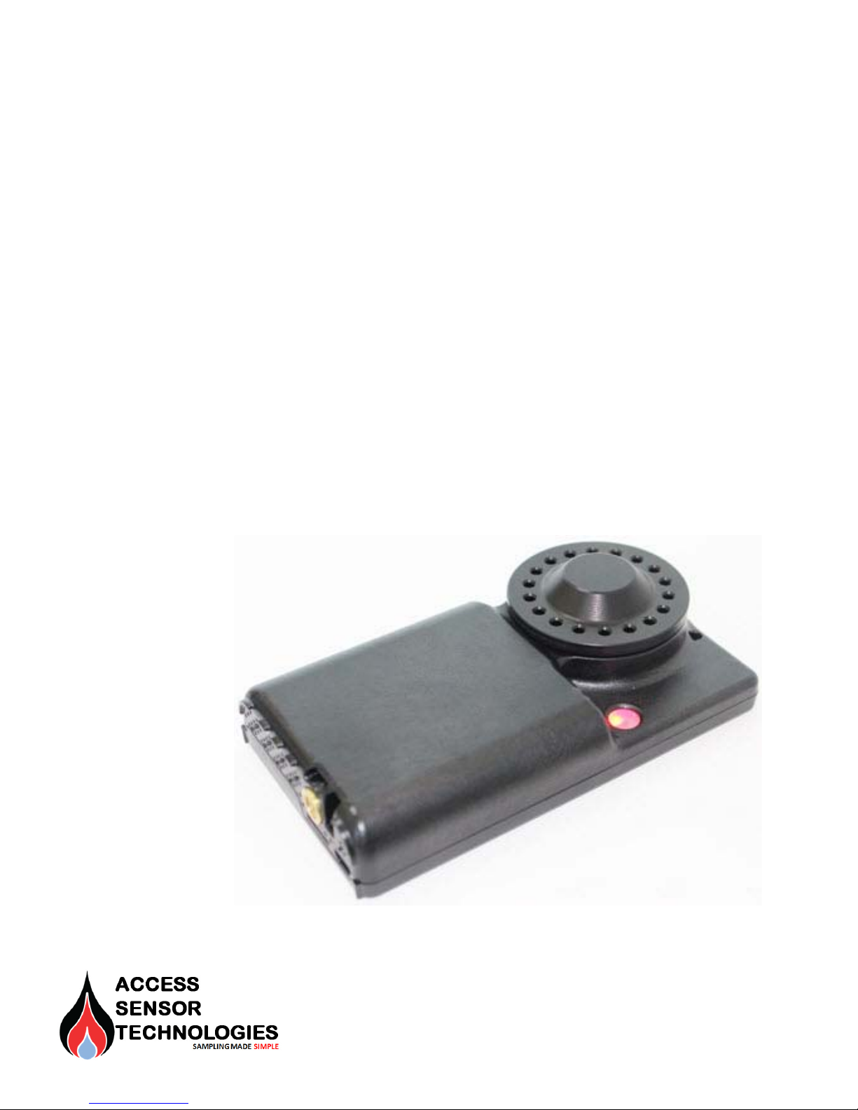
UPAS at a Glance . . . . . . . . . . . . . . . . . . . . . . . . . . . . . . . . . . . . . . . . . . . . . . . . . . . . . . . . . . .5
Recommended UPAS Filter Membranes . . . . . . . . . . . . . . . . . . . . . . . . . . . . . . . . . . . .6
2 UPAS Physical Setup
General Setup . . . . . . . . . . . . . . . . . . . . . . . . . . . . . . . . . . . . . . . . . . . . . . . . . . . . . . . . . . . . . .7
Power On/Off Sequence . . . . . . . . . . . . . . . . . . . . . . . . . . . . . . . . . . . . . . . . . . . . . . . . . . . .8
Turning the UPAS On . . . . . . . . . . . . . . . . . . . . . . . . . . . . . . . . . . . . . . . . . . . . . . . . . . . .8
Turning the UPAS Off . . . . . . . . . . . . . . . . . . . . . . . . . . . . . . . . . . . . . . . . . . . . . . . . . . . .8
Installing / Removing Inlet, Filter Cartridge, and Sampling Filter . . . . . . . . . . . 11
Removing / Installing the Cyclone Inlet . . . . . . . . . . . . . . . . . . . . . . . . . . . . . . . . 11
Removing / Installing the Filter Cartridge . . . . . . . . . . . . . . . . . . . . . . . . . . . . . . 11
Removing / Installing the Sampling Filters and Chain of Custody . . . . . . . 12
Cleaning the UPAS . . . . . . . . . . . . . . . . . . . . . . . . . . . . . . . . . . . . . . . . . . . . . . . . . . . . . . . . 13
Cleaning the Outer Housing . . . . . . . . . . . . . . . . . . . . . . . . . . . . . . . . . . . . . . . . . . . 13
Cleaning the Cyclone Inlet . . . . . . . . . . . . . . . . . . . . . . . . . . . . . . . . . . . . . . . . . . . . . 13
Cleaning the 37 mm Filter Cartridge . . . . . . . . . . . . . . . . . . . . . . . . . . . . . . . . . . . 17
Optional – Greasing the Cyclone Input . . . . . . . . . . . . . . . . . . . . . . . . . . . . . . . . . . . . 19
Charging the UPAS Internal Battery . . . . . . . . . . . . . . . . . . . . . . . . . . . . . . . . . . . . . . . 20
Charging the Battery when UPAS powered ON and Idle . . . . . . . . . . . . . . . . 20
Charging the Battery while UPAS Actively Sampling . . . . . . . . . . . . . . . . . . . 20
Using an External Battery to Extend Available Runtime . . . . . . . . . . . . . . . . 21
Installing / Removing the microSD Card . . . . . . . . . . . . . . . . . . . . . . . . . . . . . . . . . . . 21
Mounting the UPAS . . . . . . . . . . . . . . . . . . . . . . . . . . . . . . . . . . . . . . . . . . . . . . . . . . . . . . . 22
Mounting the UPAS for Personal Breathing Zone Sampling . . . . . . . . . . . . 22
Mounting the UPAS for Fixed Site Sampling . . . . . . . . . . . . . . . . . . . . . . . . . . . 23
Flow Rate Verification and Adjustment . . . . . . . . . . . . . . . . . . . . . . . . . . . . . . . . . . . 24
Required Apparatus . . . . . . . . . . . . . . . . . . . . . . . . . . . . . . . . . . . . . . . . . . . . . . . . . . . 24
Measuring Flow Rate . . . . . . . . . . . . . . . . . . . . . . . . . . . . . . . . . . . . . . . . . . . . . . . . . . 24
Updating / Flashing the UPAS Firmware . . . . . . . . . . . . . . . . . . . . . . . . . . . . . . . . . . . 26
Firmware Release Notes, Installation Procedure for UPAS v2 Sampler 26

2 Access Sensor Technologies UPAS User Guide
3 Sample Run Setup / Initialization on the Mobile Device App
Installing and Updating the Mobile Device Application . . . . . . . . . . . . . . . . . . . . .30
Install and Run the App on an Android Operating System . . . . . . . . . . . . . . .30
Install and Run the App on an Apple iOS Operating System . . . . . . . . . . . . .35
Sample Run Setup and Programming in the App (Android and iOS) . . . . . . . . .37
Setting a Start Time for the Next Sample Run . . . . . . . . . . . . . . . . . . . . . . . . . . . . .42
Updating the Mobile Device App . . . . . . . . . . . . . . . . . . . . . . . . . . . . . . . . . . . . . . . . . .45
Adjusting the Flow Rate using the Flow Offset in the App . . . . . . . . . . . . . . . . .45
UPAS App Lock to Hold Setup Parameters (Optional) . . . . . . . . . . . . . . . . . . . . . .46
4 Accessing and Interpreting Sample Log Files
Transfer the Log File to a PC from the microSD Card . . . . . . . . . . . . . . . . . . . . . .47
Download App Log File via Bluetooth from Android Devices . . . . . . . . . . . . . . .47
Download App Log Files via Bluetooth from iOS Devices . . . . . . . . . . . . . . . . . .48
Download Log Files from IOS Device to Mac Computer . . . . . . . . . . . . . . . . .48
For PC computers, connect IOS device to PC Computer . . . . . . . . . . . . . . . .49
Interpreting Log File Data . . . . . . . . . . . . . . . . . . . . . . . . . . . . . . . . . . . . . . . . . . . . . . . . .50
5 Diagnostics and Troubleshooting
Ensuring Adequate Battery Endurance . . . . . . . . . . . . . . . . . . . . . . . . . . . . . . . . . . . .54
Interpreting UPAS Status / Shutdown Mode Codes . . . . . . . . . . . . . . . . . . . . . . .55
Acquiring / Sending Debug Files . . . . . . . . . . . . . . . . . . . . . . . . . . . . . . . . . . . . . . . . . . .57
Conducting a Diagnostic Test (DIAG#) . . . . . . . . . . . . . . . . . . . . . . . . . . . . . . . . . . . .57
Understanding DIAG# mode . . . . . . . . . . . . . . . . . . . . . . . . . . . . . . . . . . . . . . . . . . . .57
Steps for Activating Diagnostic Mode . . . . . . . . . . . . . . . . . . . . . . . . . . . . . . . . .58
Correcting an Incorrect UPAS Serial ID . . . . . . . . . . . . . . . . . . . . . . . . . . . . . . . . . . . .59
UPAS shuts down immediately after starting a new sample run . . . . . . . . . . .59
UPAS Not Writing Log Files to the microSD Card . . . . . . . . . . . . . . . . . . . . . . . . . .59
6 Frequently-Asked Questions
7 UPAS Specifications
8 Warranty and Repair Service

Access Sensor Technologies UPAS User Guide 3
1 Introduction
Access Sensor Technologies’ Ultrasonic Personal Air Sampler (UPAS) provides a
new paradigm of streamlined, low-cost exposure assessment to indoor air
pollution. The UPAS is a self-contained filter-integrated sampler featuring
valve-less ultrasonic pumping technology. This technology provides substantial
reductions in size, weight, noise, and cost along with increased durability over
traditional sampling equipment. The UPAS is silent and light enough to be worn in
the subject’s breathing zone, but can also be deployed in fixed site sampling
scenarios.
The UPAS system consists of two components:
• A hardware component which can be worn in the subject’s breathing zone or
mounted on a tripod (not included) for general environmental testing.
• A software component with a Bluetooth®interface allows programming,
control and data download via a mobile Android or Apple iOS application.
This User Guide describes both the hardware and the software components. It
explains how to prepare and program the UPAS and then retrieve the UPAS
sampled data.
CAUTION: The Access Sensor Technologies UPAS Sampler is designed for indoor
use only. Shield the UPAS from water, water spray, precipitation, etc.
There are no operator serviceable parts inside. Refer servicing to Access Sensor
Technologies.

4 Access Sensor Technologies UPAS User Guide
What comes with my UPAS
Your UPAS comes complete with a kit containing the following items. If you are
missing any items, contact Access Sensor Technologies.
Optional Accessories
Contact Access Sensor Technologies to purchase these accessories.
What is not provided
Description Qty
O-Ring replacement kit 1
Filter cartridges 2
PM2.5 Cyclone Inlet assembly 1
microSD Card 1
Description
Flow Measurement Adapter (for flow verification),
Additional Filter cartridges
Additional size selective Cyclone Inlet assemblies
Description Comments
USB Cable Optional USB Type A connector to Micro USB connector
Flow Meter/ Primary Required only for flow verification.
Lanyard, tripod, chest harness, armband, etc.

Access Sensor Technologies UPAS User Guide 5
UPAS at a Glance
The following photos show the UPAS and identify several key components,
There are no user-serviceable components inside. Do not attempt to open the
UPAS case. Return the UPAS to Access Sensor Technologies for repair.
Figure 1 UPAS with Cyclone Inlet Cap Removed
Hole for
attaching
a lanyard
Power button with
status indicator
light. Press and
hold for five
seconds to turn
UPAS on or off.
Micro-USB port
Micro-SD
card slot
1/4” -20 UNC
threaded insert
for mounting on
a standard
camera tripod or
similar mount.
Cyclone Inlet
(PM2.5 version
shown)
Upper half of
37 mm Filter
Cartridge
(PM2.5 specific
version shown)
Lower half of
37 mm Filter
Cartridge
(shown with filter
in place)
Optional (sold separately)
Flow-Measurement
Adapter. See “Flow Rate
Verification and
Adjustment” on page 24.
NOTE:

6 Access Sensor Technologies UPAS User Guide
Recommended UPAS Filter Membranes
Table 1 Filter Membranes
General
Gravimetric analysis
Dissolvable (for chemical Analysis)
Scannable via XREF EDS, etc.
Microscopy Analysis
Biological Sampling
Relative Flow Resistance
(lower means longer UPAS battery life)
Manufacturer Product
Family Product
ID Filter Media Material Type
Filter Media Pore Size ( m)
Support Ring Material
+ – + + + 1.0 Tisch Scientific PTFE SF17382 PTFE (Teflon) membrane 5.0 none
+ – + + + 1.2 GE Lifesciences
Whatman TE 38 10411108 PTFE (Teflon) membrane 5.0 none
+ – + + + 1.3 Pall Laboratory Teflo R2PJ037 PTFE (Teflon) membrane 2.0 PMP Ring
+ – + + + 1.7
Measurement
Technology
Laboratories (MTL)
PTFE PT37P-PF03 PTFE (Teflon) membrane 2.0 FEP Ring
+ ± + + + 4.2 SKC PVC 225-5-37 PVC membrane 5.0 none
+ – + – – 5.0 Pall Laboratory Tissuquartz 2500QAT-UP Quartz fiber (unbonded) - none
+ – + – – 5.1 Pall Laboratory EMFAB TX40HI20WW-
37 mm
Borosilicate microfiber w/
woven glass, PTFE bonded -none
+ – + + + 6.6 Pall Laboratory Zefluor P5PJ037 PTFE (Teflon) membrane 2.0 PTFE Ring
± + + + + 10.0 SKC MCE 225-1938 Mixed cellulose ester (MCE)
membrane 5.0 none
± + + + + 16.2 SKC MCE 225-1939 Mixed cellulose ester (MCE)
membrane 0.8 none
± + + + + 16.2 SKC MCE 225-334 Mixed cellulose ester (MCE)
membrane 0.8 none
± + + + + 17.7 EMD Millipore MF AAWP03700 Mixed cellulose ester (MCE)
membrane 0.8 none
± + + + + 19.0 GE Lifesciences
Whatman ME27 10400909 Mixed cellulose ester (MCE)
membrane 0.8 none
+means typical use, ±means optional use, –means not typically used.

Access Sensor Technologies UPAS User Guide 7
2 UPAS Physical Setup
General Setup
The UPAS Sampler monitors air pollution by passing ambient air at a regulated
flow rate through a size-selective inlet and then a 37 mm filter inside of a
cartridge.
An iOS (Apple) or Android mobile device application (the “App”) programs
parameters into the UPAS and initializes sampling runs. You can assign a unique
sample name and ‘filter cartridge ID” for each sample, and transfer log files to a
computer for data analysis, and more.
Your UPAS Sampler is identified by the serial number ID on the back of the UPAS.
You will need this serial number ID when connecting the UPAS to the mobile
device App.

8 Access Sensor Technologies UPAS User Guide
Power On/Off Sequence
Turning the UPAS On
Prior to powering up the UPAS, ensure that you have installed the microSD card
and that you have properly installed a filter cartridge and Cyclone Inlet cap.
Press the power button firmly until it clicks. Continue holding until the LED light
turns on (about five seconds). Release the button. Note that the pushbutton
requires an uninterrupted hold down of at least five seconds. If pressing the
pushbutton is interrupted, the UPAS does not power on; repeat the process.
The button light should briefly be a blue/cyan color indicating that the unit is
powering up. Watch the power button for the power-on status indicator
sequence. Refer toFigure 2 on page 9 and Table 2 on page 10 for the power-on
sequence.
CAUTION: Never run the UPAS without a 37 mm filter cartridge with filter in place.
It is possible to get contaminants in the unit. Dust and other particulates may
damage the pumping elements.
Turning the UPAS Off
Press the power button firmly until you feel a click. Continue to hold it in this state
for at least five seconds, until the LED light turns off. Release the button. If the unit
has been successfully powered down the LED status light is off. If the UPAS fails to
shut down, try again with a fresh five second button hold.

Access Sensor Technologies UPAS User Guide 9
Figure 2 UPAS Power-On sequence

10 Access Sensor Technologies UPAS User Guide
Table 2 Power-on Sequence Status Light Indication. (UPAS Firmware Version 102)
Sequence / Test LED Status Indicator Meaning / Definition
Start-up Sequence
1
Power-on the
UPAS by
pressing the
power button >5
seconds
Cyan light flashes once then
Green light flashes once UPAS is powered on, start-up sequence beginning.
2
Battery State of
Charge (SOC)1,2
Indication
(UPAS flashes
one of these
codes)
Blue (cyan) light flashes once SOC is < 25%
Blue (cyan) light flashes twice SOC is 25 to 50%
Blue (cyan) light flashes 3
times SOC is 50 to 75%
Blue (cyan) light flashes 4
times SOC is 75 to 96%
Blue (cyan) light flashes 4
times then Green flashes
once
SOC is > 96%
3Test for microSD
Card3Red light flashes indefinitely No microSD card is installed in the UPAS.
4Test for GPS
Date/Time4Pink light flashes indefinitely GPS Date/Time stamp is lost. UPAS start-up start-up
sequence stops if it needs GPS synchronization.
5Bluetooth® Low
Energy (BLE)
Initialization
Blue (cyan) light on BLE is starting.
Pink light on BLE ready and waiting for App connection for programming.
Do not connect App until pink light appears.
1 If the UPAS is plugged into a computer or charger and powered on, the LED displays a repeating charge-status light sequence until the UPAS is
unplugged and Bluetooth will not be available for connection.
2 If the UPAS is already powered-on when connected to a computer or charger, the normal LED indicators continues, and Bluetooth connection will
be available.
3 A microSD card must be installed to use the UPAS. All data is logged to the microSD card. If missing, start-up sequence stops here until microSD
card is in place
4 Set the GPS Date/Time by placing UPAS outdoors to capture the GPS signal. The process should take five minutes or less. If missing, start-up
sequence stops here until GPS date/time is synchronized

Access Sensor Technologies UPAS User Guide 11
Installing / Removing Inlet, Filter Cartridge, and Sampling Filter
Removing / Installing the Cyclone Inlet
1 Place the UPAS Sampler on a flat surface.
2 Remove the Cyclone Inlet by firmly holding the UPAS on the flat surface
while unscrewing the Cyclone Inlet (turn counter-clockwise).
CAUTION: Never run the UPAS without a 37 mm filter cartridge with filter in place.
It is possible to get contaminants in the unit. Dust and other particulates may
damage the pumping elements.
Install the Cyclone Inlet by carefully screwing the Inlet back onto the UPAS body.
Be careful not to cross-thread the Inlet.
Removing / Installing the Filter Cartridge
1 Place the UPAS Sampler on a flat surface.
2 Remove the Cyclone Inlet. (See above).
3 Place the filter cartridge, label down, into the inlet socket of the UPAS.
See the following photos. Make certain the cartridge is centered in the
UPAS inlet socket.
.
4 Firmly screw Cyclone Inlet cap down, just beyond finger tight.
Filter cartridge is installed
upside down in UPAS
Filter cartridge properly
installed in UPAS
Filter Cartridge

12 Access Sensor Technologies UPAS User Guide
Removing / Installing the Sampling Filters and Chain of Custody
The following instructions describe removing and installing aerosol sampling
filters (user supplied) in a UPAS Filter Cartridge. Handling and processing aerosol
sampling filters should be done per sampling protocol defined by the
organizational standard being followed. “Recommended UPAS Filter Membranes”
on page 6 lists all recommended sampling filters.
The filter membranes are fragile; handle with care. Do not handle the filter
membranes with your bare hands. Always use clean tweezers.
For most air sampling applications, it is vital to maintain the integrity of collected
samples and track the history of samples. Used filter cartridges need to be
removed from each UPAS Sampler and returned to their original packages.
Do not open filter cartridges unless the sampling protocol instructs you to do
so.
1 Wash and dry your hands thoroughly.
2 Unscrew the black Cyclone Inlet Cap from the front of the UPAS device.
3 Remove the filter cartridge from the UPAS. Hold the filter cartridge only by
the edges.
4 Return the filter cartridge to its original package.
5 Seal the package.
6 Return the package to the agency / organization sponsoring the test.
NOTE:
NOTE:

Access Sensor Technologies UPAS User Guide 13
Cleaning the UPAS
Cleaning the Outer Housing
Clean the outside of the UPAS Sampler with a soft, slightly dampened lint-free
cloth. It is safe to use either a detergent or soap solution or ethanol or isopropyl
alcohol on the cloth. Do not use any other chemical solvents.
Cleaning the Cyclone Inlet
Wash and rinse the individual inlet pieces under clean running water. If clean
running water is not available, use bottled water from a spray bottle. Use a
detergent such as dish soap. Alternately, use ethanol or isopropyl alcohol. Do not
use any other chemical solvents.
Select one or more different small, soft-bristled brushes that can reach all the
internal surfaces of the inlet. Specifically, one which can reach the end of the
pointed conical chamber cavity of the cyclone cap. See the following photos.
Most particulates can be easily observed, they have a light brown or gray
coloration and show up well against the black UPAS components.
Clean all internal and external surfaces of the outer Cyclone Inlet cap and inner
Cyclone Insert before every use of the UPAS.
1 Unscrew and remove the Cyclone Inlet Cap from the body of the UPAS
Sampler.
2 With a small flat screwdriver, key, coin, etc., gently pry the inner Cyclone
Insert from the outer Cyclone Inlet.
Cyclone Inlet Cap
(bottom side) Cyclone Insert
(bottom)
Inspect and clean the
CycloneInsertO-Rings
(top and bottom)
Foam tipped brush

14 Access Sensor Technologies UPAS User Guide
3 Carefully inspect and clean the inside of the cone in the Cyclone Inlet Cap
with a small soft-bristled brush or pointed foam applicator. Do not use
round-tip cotton swabs or any other brush/swab that is not capable of
reaching the bottom of the pointed conical chamber cavity of the cyclone
cap. Any brush/swab that is too blunt or round may force particulates into
the bottom point. Any particulates remaining at the bottom point of the
cyclone cap chamber can become dislodged during subsequent sampling
runs and contaminate the filter.
4 Clean all surfaces of the Cyclone Insert part. With a small soft brush or a
pointed foam applicator, Make certain the Cyclone Air Inlet hole is not
obstructed, and free of any debris. Use a small, soft bottle brush or pipe
cleaner to clean the Cyclone Air Inlet hole.
If grease was previously used, use isopropyl alcohol or ethanol to remove any
remaining grease residue. Do not use any other chemical solvents.
NOTE:

Access Sensor Technologies UPAS User Guide 15
Do not use any sharp or metallic tool on this part; it is plastic and can become
scratched or otherwise damaged.
5 After cleaning, verify that both the small, upper and large, lower O-ring
seals are in place (not missing), and free of damage. These are sundry
spare components included with each new UPAS. Replace them if they are
missing or damaged.
Use a small,
cone-shaped foam
brush to make
certain the Cyclone
air inlet hole is not
obstructed
Inspect and clean
the inner Cyclone
Insert O-Ring
Cyclone Insert
(top view)
NOTE:
Inspect and clean
the O-Rings in the
inside cover

16 Access Sensor Technologies UPAS User Guide
6 Allow the Cyclone Inlet components to air dry.
7 Reinstall the Cyclone Insert into the Cyclone Inlet Cap with a twisting and
pressing motion. There is no specific angular or indexing orientation. If the
Inside Cover does not fully snap onto the Inlet Cap, it indicates that the
O-ring is not moving into position and may be damaged. When the cap is
re-attached to the UPAS body, the two pieces will press together.
Twist and press together

Access Sensor Technologies UPAS User Guide 17
Cleaning the 37 mm Filter Cartridge
Remove and transfer any exposed air sample filters per the chain-of-custody
protocol referenced in “Removing / Installing the Sampling Filters and Chain of
Custody” on page 12.
1 Both the top half and the bottom half of the filter cartridge have two small
tabs. Use these tabs to separate the two halves of the filter cartridge.
The top piece has a nozzle; the bottom piece has protrusions to support
the filter.
2 Place a new filter membrane into a clean cartridge. Do not use a backing
pad! For a list of recommended filter membranes, see “Recommended
UPAS Filter Membranes” on page 6.
3 Press the two halves back together with tabs slightly misaligned. If they
don’t easily snap together, check for the presence of the black O-ring on
the top (nozzle) piece.
NOTE:
Tabs
Tabs
Filter Cartridge bottom Filter Cartridge top

18 Access Sensor Technologies UPAS User Guide
Note the three-character code on top of each filter cartridge. The
three-character code is an identifier used to track the filter cartridge. Enter this
code into the App as the Cartridge ID. This code is saved as part of the Log file and
keeps the filter associated with the data.
Cleaning the Filter Cartridges
If you reuse a filter cartridge, it must be thoroughly cleaned between uses.
1 Separate the two halves of the filter cartridge as explained above.
Remove the filter membrane for analysis. See “Removing / Installing the
Filter Cartridge” on page 11.
2 Use soapy water and a soft-bristled brush to carefully clean all surfaces of
the cartridge.
3 Thoroughly rinse the cartridge under clean running water. If running water
is not available, use bottled water from a spray bottle. Alternately, use
alcohol.
Make sure that both halves of the cartridge are clean and dry before re-loading
the cartridge with a clean filter membrane.
Slight tab
misalignment
recommended
Three-character
code
Table of contents
Popular Medical Equipment manuals by other brands

Doctor Life
Doctor Life RevitaPump LX7 user manual

HemoCue
HemoCue Hb 301 operating manual

Guardian
Guardian Guardian Easytrack System 900-0880 Installation and instruction manual

Reison
Reison 10-382-K Abridged user manual

B.A. International
B.A. International Ultimate BA101 Operation manual

Atos Medical
Atos Medical Provox Dilator 17 manual