10
20
21
24
33
35
1.1. Mechanism group
1.2. Working environment data
1.3. Hook Suspension Series,Single speed / Dual speed
* Specification & Dimensions
1.4. Motor Trolley mounted series,Single speed / Dual speed
* Specification & Dimensions
1.5. Low Headroom Chain Hoist (VFD Control)
* Specification & Dimensions
* Electric Wring Diagram of Hook Suspension Series
* Electric Wring Diagram of Motor Trolley Mounted Series
1.6. Lug Mount Plain Trolley Hoist
* Specification & Dimensions
4.1. Checking of product
4.2. Installation process
4.2.1. Checking of electricity
4.2.2. Installation of "Bolt with vent hole"
4.2.3. Installation of Chain Container to hoist body
4.2.4. Oil lubrication on load chain and onto chain container
* Maximum Chain-Lift-Length, according to each Chain Container
4.2.5. Checking Load Chain after installation
4.2.6. Incorrect Phase Checking
4.3 Installation of the motor trolley mounted series
4.3.1 How to install trolley on the runway I-Beam.
* parts to adjust i-beam width
* how to set up the i-beam width of motor trolley
* applied collar numbers for each trolley capacity on i-beam.
4.4. Install start up
6.1. Electrical connection
6.2. Chain container
* How to install Chain Container
6.3. Chain stopper in the chain container
6.4. Chain stopper spring
6.5. Load chian
6.5.1. Measurment of Wear and Replacement of the chain
6.5.2. Checking chain alignment (the welded part outward from the center)
6.6. Hook
6.6.1. Measurement of the wear on the hooks
3.1. Warning and Caution
3.2. Name plates and labels on products.
2.1. Trolley series and Classification of electric wiring
Features
General description of manual
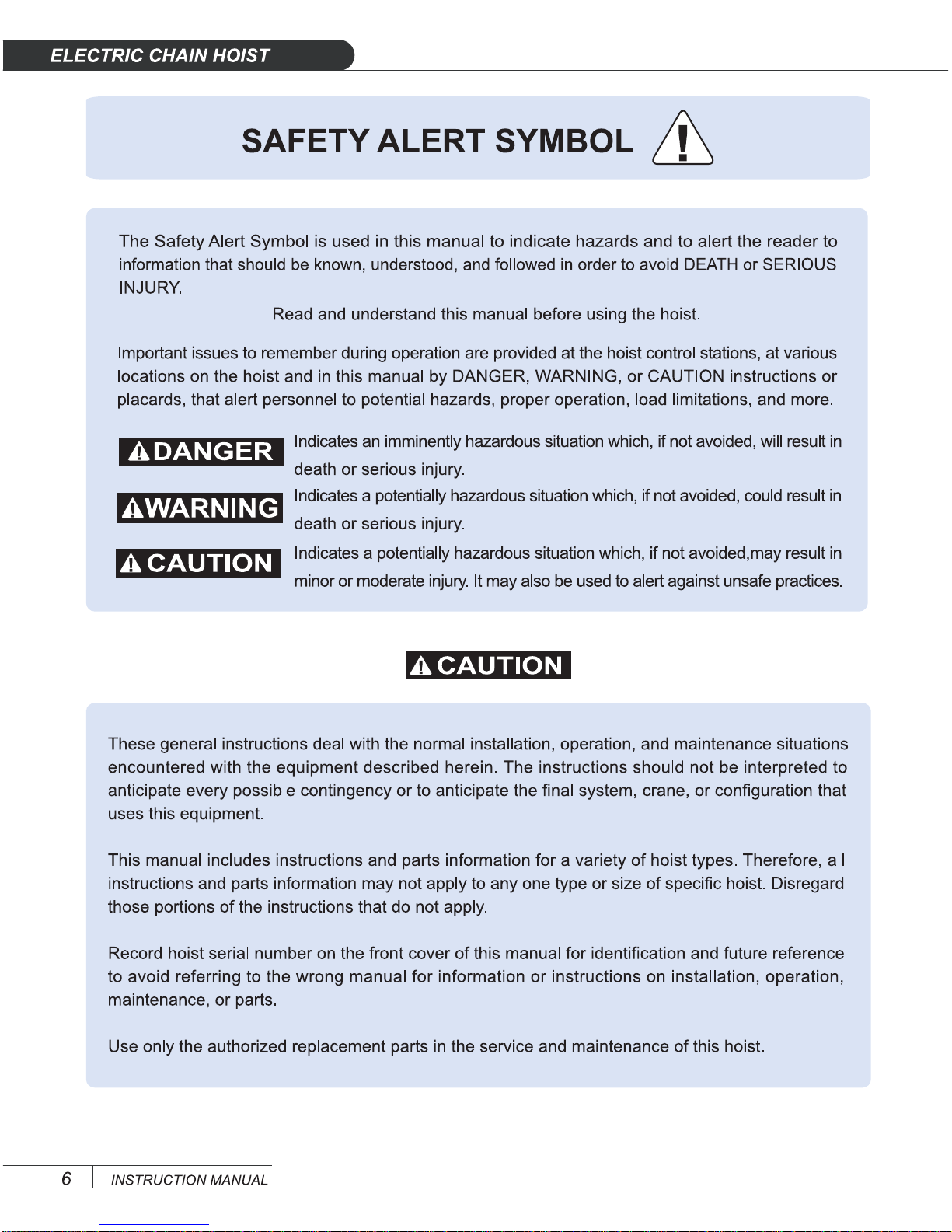
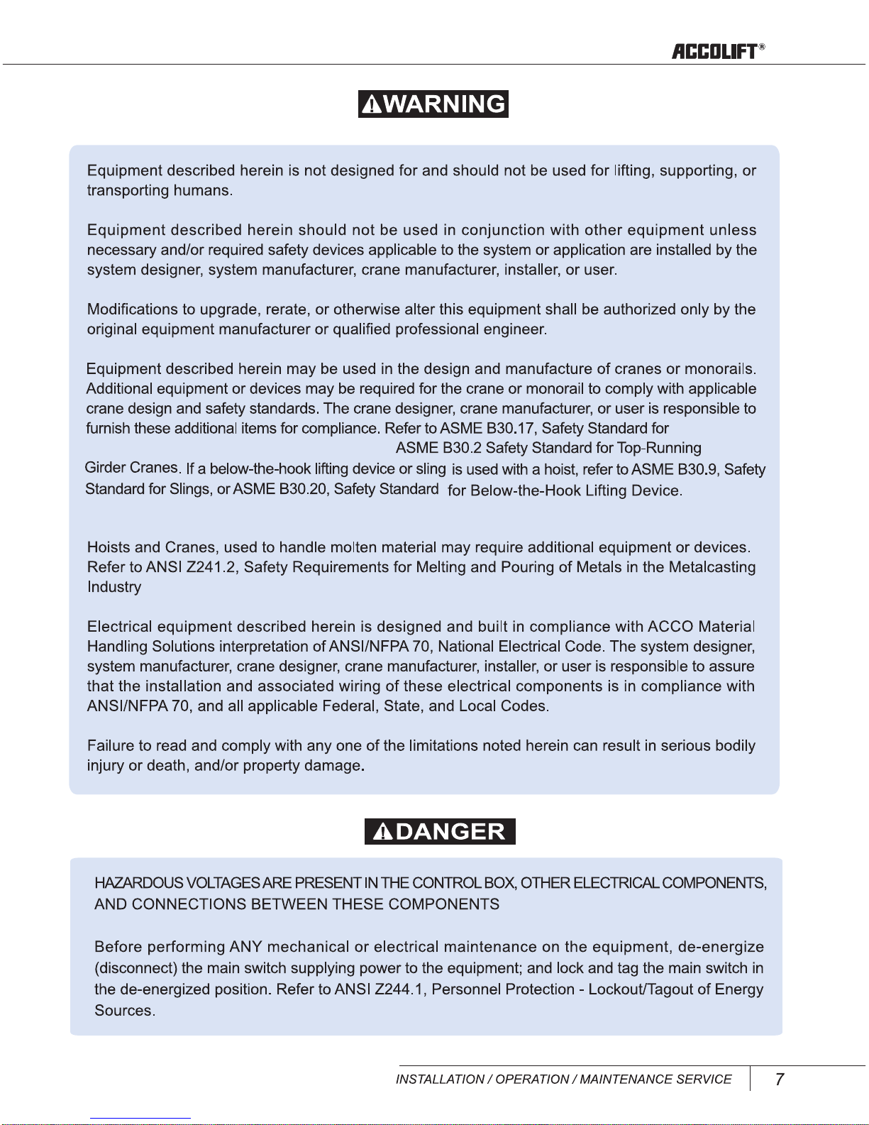
Safety precautions
Installation
Maintenance and servicing
Precaution during operation