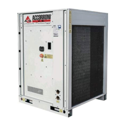
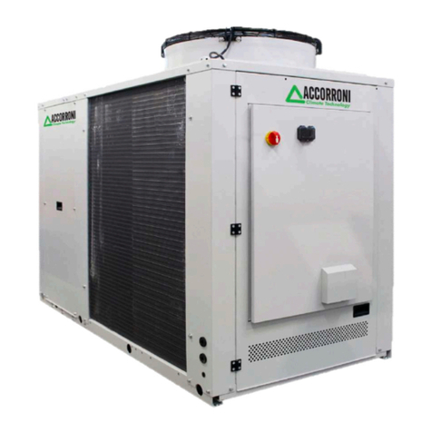
Accorroni PACK DUE 7 User manual


1
0310‐2012D.P.
‐Thesections5.1,9.3and22.2havebeenupdated,thechangeoftheheatingwireofthe
antifreezingkitisconsidered(it’sdirectlyenergizedandequippedwithanintegrated
thermostat).
0209‐2012D.P.
‐Inthesection8.7weaddedatableofalarms,descriptionsandcauses.
‐ Inthesection13.1thenumbercircuitofthecondensorofthemodel16,andwe
updatedthedimensionsofthepackingofthemodels12and16.
‐Inthesection15thecurveisupdated.
‐Thesection17isimprovedwithdescriptionsmoreclearandtables.
‐Wiringdiagramsareupdated(wiringofthemanostat).
0107‐2012
0006‐2012D.P./
Rev Date Author Descreption of updates
Catalogo/Catalogue/Katalog/Catalogue
MTE14110C5420‐03
Serie/Series/Serie/Serie/Série
CHILLERSANDINVERTERAIR/WATERHEATPUMPSWITHAXIALFANSANDREMOTECONDENSINGUNITS
D.P.‐RefrigerantchargeischangedforthemodelsPACK DUE12and16.

2
INDEX
1AIMANDCONTENTSOFTHISMANUAL ....................................................................... 5
1.1 HOWTOKEEPTHISMANUAL.................................................................................................................................................. 5
1.2 GRAPHICSYMBOLS................................................................................................................................................................. 5
2SAFETYLAWS .............................................................................................................. 5
3GENERALSAFETYGUIDELINES ..................................................................................... 5
3.1 HEALTHANDSAFETYOFWORKERS ........................................................................................................................................ 6
3.2 PERSONALPROTECTIONEQUIPMENTS .................................................................................................................................. 6
3.3 SAFETYSYMBOLS.................................................................................................................................................................... 6
3.4 REFRIGERANTSAFETYDATASHEET ........................................................................................................................................ 7
4TECHNICALCHARACTERISTICS ..................................................................................... 8
4.1 FRAME.................................................................................................................................................................................... 8
4.2 REFRIGERANTCIRCUIT............................................................................................................................................................ 8
4.3 COMPRESSORS ....................................................................................................................................................................... 8
4.4 AIRSIDEEXCHANGERS............................................................................................................................................................ 8
4.5 FANS ....................................................................................................................................................................................... 8
4.6 USERHEATEXCHANGERS ....................................................................................................................................................... 8
4.7 ELECTRICBOX ......................................................................................................................................................................... 8
4.8 MICROPROCESSORS ............................................................................................................................................................... 8
4.9 MONITORINGANDPROTECTIONDEVICES ............................................................................................................................. 9
4.10 HYDRAULICCIRCUIT ............................................................................................................................................................... 9
4.11 FANSPEEDCONTROLLER........................................................................................................................................................ 9
5AVAILABLEVERSIONS .................................................................................................. 9
5.1 ACCESSORIES.......................................................................................................................................................................... 9
6INSTALLATION ............................................................................................................. 9
6.1 GENERALITY............................................................................................................................................................................ 9
6.2 LIFTINGANDHANDLING....................................................................................................................................................... 10
6.2.1 INDOORUNIT ............................................................................................................................................................... 10
6.2.2 OUTDOORUNIT............................................................................................................................................................ 10
6.3 LOCATIONANDMINIMUMTECHNICALCLEARANCES .......................................................................................................... 10
6.3.1 INDOORUNIT ............................................................................................................................................................... 10
6.3.2 OUTDOORUNIT............................................................................................................................................................ 10
6.4 HYDRAULICCONNECTIONS .................................................................................................................................................. 10
6.4.1 CONNECTIONDIAGRAMS............................................................................................................................................. 10
6.4.2 PLANTLAYOUTDESIGN ................................................................................................................................................ 11
6.4.3 CONNECTIONSPOSITIONS ........................................................................................................................................... 12
6.4.4 DRAINAGECONNECTION ............................................................................................................................................. 12
6.5 REFRIGERANTDIAGRAM ...................................................................................................................................................... 13
6.6 ELECTRICALCONNECTIONS .................................................................................................................................................. 13
6.6.1 TERMINALBLOCKCONNECTIONS ................................................................................................................................ 14
7STARTUP................................................................................................................... 15
8INDOORUNITCONTROLPANEL ................................................................................. 16
8.1 LED........................................................................................................................................................................................ 16
8.2 FUNCTIONSOFBUTTONS ..................................................................................................................................................... 16
8.2.1 LEVELSOFACCESS ........................................................................................................................................................ 16
8.3 DESCRIPTIONOFTHEMAINDISPLAY.................................................................................................................................... 17
8.3.1 NAVIGATIONBETWEENDISPLAYS................................................................................................................................ 17

3
8.4 OPERATINGMODES.............................................................................................................................................................. 17
8.4.1 OPERATIONMODESETTING......................................................................................................................................... 17
8.5 PROCEDURE.......................................................................................................................................................................... 17
8.5.1 SET‐POINTSELECTION .................................................................................................................................................. 17
8.6 DESCRPTIONOFFUNCTIONS ................................................................................................................................................ 17
8.6.1 ACCESSTOTHEFUNCTIONS......................................................................................................................................... 17
8.7 ALARMS................................................................................................................................................................................ 18
8.8 ADJUSTMENTOFSANITARYWATERVALVE.......................................................................................................................... 18
9MICROPROCESSORUSERINTERFACE ......................................................................... 18
9.1 DISPLAY ................................................................................................................................................................................ 19
9.2 LED........................................................................................................................................................................................ 19
9.3 ANTIFREEZEPROTECTIONRESISTANCES(IFTHEKASACCESSORYISPRESENT) ............................................................................. 19
9.4 ALARMS................................................................................................................................................................................ 19
9.4.1 Sensoralarms ............................................................................................................................................................... 19
9.4.2 Timeoutinverter.......................................................................................................................................................... 19
9.4.3 Highpressure ............................................................................................................................................................... 19
9.4.4 Highpressureflowswitch(inserieswiththecompressoroutletprobe) .................................................................... 19
9.4.5 Lowpressure ................................................................................................................................................................ 19
9.5 POWERFAILURE ................................................................................................................................................................... 19
9.6 ALARMSLIST......................................................................................................................................................................... 20
10 SHUTDOWNSFORLONGPERIODS ............................................................................. 20
11 MAINTENANCEANDPERIODICCHECKS ..................................................................... 20
11.1 ENVIRONMENTALPROTECTION ........................................................................................................................................... 21
12 WHENTHEUNITGOESOUTOFSERVICE .................................................................... 21
13 TECHNICALDATA....................................................................................................... 22
13.1 OUTDOORUNITS .................................................................................................................................................................. 22
13.2 INDOORUNITS...................................................................................................................................................................... 23
14 ELECTRICDATA .......................................................................................................... 23
15 EFFECTIVEHEADPRESSURES...................................................................................... 24
16 PERFORMANCESCURVES........................................................................................... 25
16.1
16.2
16.3
16.4
17
17.1 EVAPORATORWATERFLOWRATE ................................................................................................................................................. 33
17.2 COLDWATERTEMPERATURE(SUMMEROPERATION) ........................................................................................................................ 33
17.3 HOTWATERTEMPERATURE(WINTEROPERATION) ........................................................................................................................... 33
17.4 AMBIENTAIRTEMPERATURE........................................................................................................................................................ 33
18 CORRECTIONFACTORS .............................................................................................. 34
18.1 CORRECTIONFACTORS:OPERATIONWITHGLYCOL ..................................................................................................................... 34
19 DIMENSIONS ............................................................................................................. 34
19.1 INDOORUNIT ....................................................................................................................................................................... 34
19.2 OUTDOORUNIT.................................................................................................................................................................... 35
OPERATIONLIMITS.................................................................................................... 33
MOD.PACK DUE9 ................................................................................................................................................................. 27
MOD.PACK DUE12 ............................................................................................................................................................... 29
MOD.PACK DUE16 ............................................................................................................................................................... 31
MOD.PACK DUE7 ................................................................................................................................................................. 25

4
20 ACCESSPROCEDURETOINTERNALPARTS ................................................................. 35
20.1 INDOORUNIT ....................................................................................................................................................................... 35
20.2 OUTDOORUNIT.................................................................................................................................................................... 35
21 COMPONENTSOFINDOORANDOUTDOORUNITS .................................................... 36
21.1 INDOORUNIT ....................................................................................................................................................................... 36
21.2 OUTDOORUNIT.................................................................................................................................................................... 36
22 WIRINGDIAGRAMS ................................................................................................... 37
22.1
22.2
22.2.1
22.2.2
22.2.3
23 SOLARMODULE(OPTIONALACCESSORY) .................................................................. 41
23.1
23.2 WIRINGDIAGRAM ................................................................................................................................................................ 42
ASSEMBLY............................................................................................................................................................................. 41
OUTDOORUNITS .................................................................................................................................................................. 38
WiringdiagramofPACK DUE12 .................................................................................................................................. 39
INDOORUNITS...................................................................................................................................................................... 37
WiringdiagramofPACK DUE9 .................................................................................................................................... 38
WiringdiagramofPACK DUE16 .................................................................................................................................. 40

5
theoperatorthusmeetingtherequirementslistedinthe2006/42/CEEquipmentDirectiveandfollowingamendments.
1AIMANDCONTENTSOFTHISMANUAL
addressedtomachineoperatorsanditenablesthemtousetheequipmentefficiently,eveniftheydonothaveanyprevious
specificknowledgeofit.
Thismanualdescribesthecharacteristicsoftheequipmentatthetimeitisbeingputonthemarket;therefore,itmaynotcapture
ergonomics,safetyandfunctionalityofitsproducts.
1.1 HOWTOKEEPTHISMANUAL
Themanualhastobealwayskeptwiththeunititrefersto.Ithastobestoredinasafeplace,awayfromthedustandmoisture.It
hastobeaccessibletoalluserswhoshallconsultitanytimetheyareindoubtonhowtooperatetheequipment.
versionsofthe
referencematerial.Thecustomershallstoreanyupdatedcopyofthemanualorpartsofitdeliveredbythe
manufacturerasanattachmenttothismanual.
andthemaintenanceofitsownunits.
1.2 GRAPHICSYMBOLS
Indicatesoperationsthatcanbedangerousforpeopleand/ordisruptsthecorrectoperationoftheequipment.
Indicatesprohibitedoperations.
Indicatesimportantinformationthattheoperatorhastofollowinordertoguaranteethecorrectoperationofthe
equipmentincompletesafety.
2SAFETYLAWS
inforceandwithotherEuropeanandnationalnormsasrequiredbytheCouncilDirective(98/37andlateramendments).
Theequipmentsmeetalsothefollowingrequirements:
•ENISO12100Rule
•ENISO13857Rule
•EN378‐1,378‐2,378‐3e378‐4Rules
•EN12735‐1Rule
•ENCEI60204‐1Rule
•EN1050Rule
•ENCEI61000‐6‐1Rule
•ENCEI61000‐6‐3Rule
•97/23/CE,2006/95/CE,2004/108/CE,2002/95/CECommunityDirectives
3GENERALSAFETYGUIDELINES
equipmentanditscontrolsandhastohavereadandunderstoodtheinformationlistedinthismanual.
It’sstrictlyforbiddentoremoveand/ortamperwithanysafetydevice.
Anyroutineornot‐routinemaintenanceoperationshallbecarriedoutwhentheequipmenthasbeenshutdown,
disconnectedfromelectricandpneumaticpowersourcesandafteritspneumaticsystemhasbeendischarged.
Donotputneitheryourhandsnorinsertscrewdrivers,spannersorothertoolsintomovingpartsoftheequipment.
Theequipmentsupervisorandthemaintenancemanhastoreceivesuitabletrainingfortheperformanceoftheir
tasksinsafety.
Operatorshavetoknowhowtousepersonalprotectivedevicesandhavetoknowtheaccident‐preventionguidelines
containedinnationalandinternationallawsandnorms.
ThePACK DUEmanualcontainsallthenecessaryinformationforthebetteruseoftheequipmentundersafetyconditionsfor
Thismanualprovidesbasicinformationasfortheinstallation,theoperationandthemaintenanceofthePACK DUEunits.Itis
latertechnologicalimprovementsintroducedbyA2B ACCORRONI E.G. aspartofitsconstantendeavourtoenhancethe
performance,
A2B ACCORRONI E.G.reservestherighttomodifyitsproductsandrelatedmanualswithoutnecessarilyupdatingprevious
A2B ACCORRONI E.G.isavailabletogiveanydetailedinformationaboutthismanualandtogiveinformationregardingtheuse
A2B ACCORRONI E.G.’sequipmentsandtheircomponentpartshavebeendesignedincompliancewiththeharmonisedECnorms
BeforebeginningtooperateonPACK DUEunitseveryuserhastobeperfectlyknowledgeableaboutthefunctionsofthe

6
3.1 HEALTHANDSAFETYOFWORKERS
TheEuropeanCommunityhasadoptedanumberofdirectivesonworkplace’shealthandsafety,whichinclude89/391/CEE,
89/686/CEE,89/655/CEE,86/188/CEEand77/576/CEEdirectives.Everyemployershallimplementsuchprovisionsandensure
thatworkersrespectthem:
Donottamperwithorreplacepartsoftheequipmentwithoutthespecificconsentofthemanufacturer.The
manufacturershallhavenoresponsibilitywhatsoeverincaseofunauthorisedoperations.
Usingcomponents,expendablematerialsorsparepartsthatdonotcorrespondtothoserecommendedbythe
manufacturerand/orlistedinthismanualmaybedangerousfortheoperatorsand/ordamagetheequipment
Theoperator’sworkplacehastobekeptclean,tidyandfreefromobjectsthatmaypreventfreemovements.
Appropriatelightingoftheworkplaceshallbeprovidedsoastoallowtheoperatortocarryouttherequired
operationssafely.Poorortoostronglightingcancauserisks.
Ensurethatworkplacesarealwaysadequatelyventilatedandthataspiratorsareworking,ingoodconditionandin
compliancewiththerequirementsofthelawsinforce.
3.2 PERSONALPROTECTIONEQUIPMENTS
Protectiveclothing:Maintenancemenandoperatorshastowearprotectiveclothingthatcomplieswiththebasic
safetyrequirementscurrentlyinforce.Incaseofslipperyfloors,usershavetowearsafetyshoeswithnon‐slipsoles.
Gloves:Duringmaintenanceorcleaningoperationprotectiongloveshavetobeused
Maskandgoggles:Respiratoryprotection(mask)andeyeprotection(goggles)shouldbeusedduring
cleaningandmaintenanceoperations.
3.3 SAFETYSYMBOLS
Theequipmentfeaturesthefollowingsafetysigns,whichhastobecompliedwith:
Generalhazard
Electricshockhazard
WhenoperatingandmaintainingthePACK DUEunits,usethefollowingpersonalprotectiveequipments.

7
3.4 REFRIGERANTSAFETYDATASHEET
Name:R410A(50%Difluoromethane(R32);50%Pentafluoroethane(R125).
RISKSINDICATIONS
Majorrisks:Asphyxia
Specificrisks:Therapidevaporationcancausefreezing.
FIRSTAID
Generalinformations:Nevergiveanythingbymouthtoanunconsciousperson.
Inhalation:Outdoorsopenstransport.
Useoxygenorartificialrespirationifnecessary.
Donotgiveadrenalineorsimilardrugs
Eyescontact:Rinsecarefullywithwaterforatleast15minutesandconsultadoctor.
Contactwithskin:Washimmediatelywithplentyofwater.
Takeoffimmediatelythecontaminatedclothes.
FIREPREVENTION
ExtinguishingMedia:Whatever.
Specifcrisks:Increaseinpressure.
Specificsmethods: Usewaterspraytocoolcontainers
MISUREINCASODIFUORIUSCITAACCIDENTALE
Personalprecautions:Evacuatepersonneltosafeareas.
Provideadequateventilation.
Usepersonalprotectiveequipment.
Environmentalprecautions:Evaporate.
Cleaningmethod: Evaporate.
MANIPOLAZIONEESTOCCAGGIO
Manipulation
Action/technicalprecautions: Providesufficientairexchangeand/orexhaustinworkrooms.
Recommendationsforsafeuse:Donotbreathevaporsorspraymist.
Storage:Closetightlyandstoreinacool,dryandwellventilatedplace.
Storeinoriginalcontainer.Incompatibleproducts:explosive,flammablematerials,Organicperoxide
EXPOSURECONTROL/PERSONALPROTECTION
Controlparameters: AEL(8‐he12‐hTWA)=1000ml/m³foreachofthetwocomponents.
Respiratoryprotection:Forrescueandmaintenanceoperationinstoragetanksuseself‐containedrespiratorapparatus.
Thevaporsareheavierthanairandcancausesuffocationbyreducingoxygenavailableforbreathing.
Eyesprotection: Safetyglasses.
Protectionofhands: Rubbergloves.
Hygienemeasures:Donotsmoke.
PHYSICALANDCHEMICALPROPERTIES
Colour: Colourless.
Odor: Light.
Boilingpoint:‐52.8°Catatmosphericpressure.
Lightingpoint:donotignite.
Relativedensity:1.08kg/lat25°C.
Solubilityinwater:Negligible.
STABILITYANDREACTIVITY
Stability: Noreactivitywhenusedwiththeappropriateinstructions.
Materialstoavoid: Highlyoxidizingmaterials.Incompatiblewithmagnesium,zinc,sodium,potassiumandaluminum.
Theincompatibilityismoreseriousifthemetalispresentinpowerderformorifthesurfaceswere,recently,unprotected.
DecompositionproductsTheseproductsarehalogenatedcompounds,hydrogenfluoride,carbonoxides(CO,CO2),carbonylhalides.
Risks:
TOXICOLOGICALINFORMATION
Acutetoxicity:(R32)LC50/inhalation/4hours/onrat>760ml/l
(R125)LC50/inhalation/4hours/onrat>3480mg/l
Localeffects:ConcentrationssubstantiallyabovetheTLVmaycausenarcoticeffects.
Inhalationofdecomposedproductsofhighconcentrationsmaycauserespiratoryfailure(pulmonaryedema).
Longtermtoxicity:Didnotshowcarcinogenic,teratogenicormutageniceffectsinanimalexperiments.
ECOLOGICALINFORMATION
Globalwarmingpotential1730
GWP(R11=1):
Potentialdepletion0
OzoneODP(R11=1):
Disposalconsiderations:Usablewithreconditioning.

8
4TECHNICALCHARACTERISTICS
unitsareextremelyversatileandcanoperateinheatpumpmodewiththeabilityofproducinghotwateratatemperatureof55°C
forenvironmentalheatingandsanitaryapplications.TheINVERTERcompressorwithbrushlessDCmotortechnology,matched
withelectronicexpansionvalve,pumpandvariablespeedbloweraregenerallyusedforoptimizingthepowerconsumptionand
efficientoperationoftherefrigeratingcomponents.
4.1 FRAME
ensurethebestresistanceagainstatmosphericagents.Theframeisself‐supportingwithremovablepanels.Allscrewsandrivets
foroutdoorinstallationsareinstainlesssteel.
4.2 REFRIGERANTCIRCUIT
TherefrigerantgasusedintheseunitsisR410A.Therefrigerantcircuithasbeenmanufacturedbymeansofinternationalprimary
brandscomponentsandaccordingtotheUNIEN13134ruleconcerningweldingprocedures.Therefrigerantcircuitincludes:
Safetydeviceonthegasside,4wayreversecyclevalve,electronicexpansionvalve,liquidreceiver,valvesformaintenanceand
control,pressuresafetydeviceaccordingtoPEDregulation(highpressureswitch),pressuretransducerstoaccuratelyadjustthe
evaporatingandcondensingpressures,filtersforthrottlingvalvetoavoiditsclogging.
4.3 COMPRESSORS
usedwithR410refrigerant.Thecompressorsareallsuppliedwithcrankcaseheaterandthermaloverloadprotection.Theyare
mountedonarubbermaterialactingasashockabsorbers.
Thecompressorsaremountedinaseparatechamberinordertobeseparatedfromtheairstreamtoreducethenoise.The
crankcaseheaterisalwayspoweredwhenthecompressorisinstand‐by.Theinspectionispossiblethroughthefrontalpanelof
theunitthatallowthemaintenanceofthecompressorseveniftheunitisworking.
4.4 AIRSIDEEXCHANGERS
Theairsideexchangersaremadeupofcopperpipesandaluminiumfins.Thediameterofthecopperpipesis3/8”(exceptforthe
tubesaremechanicallyexpandedintothealuminiumfinstoimprovetheheatexchangefactor.Thegeometryofthesecondensers
guaranteealowairsidepressuredropandthenaerofoilblades.Theyarestaticallyanddynamicallybalancedandsupplied
completeofthesafetyfanguardaccordingtotheEN60335Rule.Theyaremountedontheunitframebyinterpositionofrubber
vibrationdampers.Theelectricmotorsareallat6poles(about800/900rpm).Themotorsaredirectlydrivenwithanintegrated
thermaloverloadprotection.TheprotectionclassofthemotorsisIP54.
4.5 FANS
Thefansareaxialtypewithaluminiumaerofoilblades.Theyarestaticallyanddynamicallybalancedandsuppliedcompleteofthe
safetyfanguardaccordingtotheEN60335rule(safetyforelectricalapparatusofdomesticandsimilaruse).Theyaremountedon
theunitframebyinterpositionofrubbervibrationdampers.Theelectricmotorsareallat6poles(about800/900rpm).The
motorsaredirectlydrivenwithanintegratedthermaloverloadprotection.TheprotectionclassofthemotorsisIP54.
4.6 USERHEATEXCHANGERS
TheuserheatexchangersaremadeupofAISI316stainlesssteelbraze‐weldedplatestype.Theuseofthesekindofheat
exchangersallowsamassivereductionoftherefrigerantchargeoftheunitcomparedtothetraditionalshell‐in‐tubeevaporators
andalsoareductionoftheoveralldimensionsoftheunit.Theuserheatexchangersarefactoryinsulatedwithflexibleclosecell
material.Eachheatexchangerisprovidedwithatemperaturesensorworkingasantifreezeprotection.
4.7 ELECTRICBOX
TheelectricboxismanufacturedaccordingtocurrentEuropeanUnionlaws.Theaccessibilitytotheboardispossibleafter
removingthefrontpaneloftheunit.TheprotectiondegreeisIP55.Theoutdoorunitterminalboardissuppliedwithvoltagefree
contactsforgeneralalarm,outdoortemperaturesensor(whenexpected).Theindoorunitterminalboardissuppliedwithsanitary
watertemperaturesensorandhandlingof3‐wayvalve.
4.8 MICROPROCESSORS
electronicexpansionvalvewhichisdrivenbythepressuretransducerssignals.Themicroprocessorisalsocapableofcontrolling
thefollowingfunctions:watertemperatureregulation,antifreezeprotection,compressor’stimesetting,compressorautomatic
startingsequence,alarmreset,alarmmanagementandoperatingLED.ThecontrolsystemtogetherwiththeINVERTERtechnology
ThePACK DUEwaterchillersandheatpumpsseriesaredesignedforapplicationsinresidentialandcommercialareas,These
AllPACK DUEunitsaremadeupofhot‐galvanisedthicksheetmetal,paintedwithpolyurethanepowderenamelsat180°Cto
TheusedDCinvertercompressorsarearotaryhermeticsingle‐phasetype(onlyforthemodelsPACK DUE7andPACK DUE9)
andtwinrotarysingle‐phase(forthemodelPACK DUE12),andscroll3‐phasestype(forPACK DUE16)designedtobe
modelPACK DUE7inwhichthediameterofthecopperpipesis5/16”)andthethicknessofthealuminiumfinsis0,1mm.The
AllPACK DUEunitsarestandardsuppliedwithamicroprocessoradoptinganoverheatingcontrollogicprogramthroughthe

9
andtheonboardsensorscontinuouslymonitorandadapttheperformanceoftheinvertercompressor,ofthepumpandofthe
conditionsrequestedbytheuser.
Allinternalunitsarestandardsuppliedwiththefollowingmonitoringandprotectiondevices:returnwatertemperaturesensor
installedatthereturnwaterpipelinefromtheplant,operatingandantifreezesensorinstalledattheoutletpipeofthewaterto
theplantandonwatersideawaterflowswitchisinstalledtoprotecttheevaporator.Allinternalunitsaresuppliedwithhigh
pressuretransducer,lowpressuretransducer,compressor’sinletandoutlettemperaturesensors,compressorsthermalprotection
device,fansthermalprotectiondevice,highpressureflowswitch.
4.10 HYDRAULICCIRCUIT
waterutilizationanddirectlyrunbythemicroprocessorthatcontrolstherelatedstartupandproperrunning.Thehydrauliccircuit
alsoincludes:expansionvessel,safetyvalve(3bar)andtheautomaticairreleasevalve.
4.11 FANSPEEDCONTROLLER
Thisdeviceisrequiredwiththeunitrunningincoolingmodewhentheoutsideairtemperatureisbelow20°C,thusreducingthe
airflowrateofthecondensorandadaptingtheevaporatingpressureinordertoallowproperrunningoftheunit.Thisdevicecan
alsobeusedtoreducethenoiseleveloftheunitwhentheoutsideairtemperaturedecreases(e.g.duringnightoperationperiod).
5AVAILABLEVERSIONS
pump,flowswitch,automaticairreleasevalveload/unloadvalve).
5.1 ACCESSORIES
AG–Anti‐vibrationrubberpadtobeinstalledinthechassisoftheunitforpossibleshockabsorption.
KAS‐antifreezingkit(thisaccessoryhavetoberequiredwhentheorderisplacedandhavetobefactoryinstalled).Itismadeup
ofanauto‐heatingcablethermostatedat5°Candwrappedaroundthebaseoftheunitnearthecondensingcoil.
6INSTALLATION
WARNING:AlltheoperationdescribedinnextchaptersMUSTBEDONEBYTRAINEDPEOPLEONLY.Beforeanyoperation
ontheunit,besurethattheelectricsupplyisdisconnected.
6.1 GENERALITY
Wheninstallingorservicingtheunit,itisnecessarytostrictlyfollowtheruleslistedinthismanual,toconformtoallthe
specificationsofthelabelsontheunit,andtotakeanypossibleprecautions.Notobservingtherulesreportedonthismanualcan
fan(2fansasforthePACK DUE16models)accordingtothevalueofcoolingpoweratanyworking
ThePACK DUEINVERTERsystemfirmreducestheplant’swatercontenttotheminimum,thatisfromtheusualvalueof
cooling12‐15l/kWto10liters(asforthePACK DUE7andPACK DUE9modeltypes)orto16liters(asforthemodel
PACK DUE12)orto20liters(asforthemodelPACK DUE16),INABSOLUTE,asforthePACK DUEunits.Becauseofthe
appliance’sreducedsize,theinstallationspace,heatlossandinstallationcosts.
4.9 MONITORINGANDPROTECTIONDEVICES
reducedwatercontent,thePACK DUEunitscanbeinstalledinplantswithoutwatertankwithadvantagesintermsofthe
DUE12andPACK
uptoavalueof10liters(asforthemodelsPACK DUE7andPACK DUE9),orof16liters(asforthemodel
absolutevalueandnottoanykWofinstalledpower.
CAUTION:Havingafixed∆T(°C),theINVERTERcontrolsystemisabletomanageplant’sminimumwatercontents
PACK DUE12),andof20liters(asforthemodelPACK DUE16).Thisvaluemakesreferencetotheliters’
ThePACK DUEchillersunitsaresuppliedwithanintegratedhydrauliccircuitincludingthecirculatingpump,suitableforchilled
PACK.DUE‐reversibleheatpumpwithintegratedhydronicsystem(expansionvessel,safetyvalve,pressuregauge,circulating
anyeventualdamagehastobequestionedtothecarrierandrecordedontheDeliveryNotebeforesigningit.A2B ACCORRONI
severedamage.
createdangeroussituations.Afterreceivingtheunit,immediatelycheckitsintegrity.Theunitleftthefactoryinperfectcondition;
E.G. tobeinformed,within8days,oftheextentofthedamage.Thecustomershouldprepareawrittenstatementofany

10
6.2 LIFTINGANDHANDLING
6.2.1 INDOORUNIT
Thehandlingmustbeperformedbyqualifiedpersonnel,properly
equippedandwithappropriateequipmentstotheweightofthe
unit,incompliancewithsafetyregulations.
6.2.2 OUTDOORUNIT
Whenunloadingandinstallingtheunit,itishighlyrecommendedto
avoidanysuddenmoveinordertoprotecttheinnercomponents.
Unitscanbeliftedbymeansofaforkliftor,inalternative,ofbelts,
beingsurenottodamagethelateralpanelsandthecover.Itis
importanttokeeptheunithorizontalduringtheseoperations.
6.3 LOCATIONANDMINIMUMTECHNICALCLEARANCES
6.3.1 INDOORUNIT
‐Placetheunitonthewall.
‐Drillholesinthemarkedpositionsandinserttheplugs.
‐Hooktheunit.
Models.L1
(mm)
L2
(mm)
H1
(mm)
H2
(mm)
3003001500300
6.3.2 OUTDOORUNIT
partiallycovertheunit)hastobeavoidedinordertopreventairrecirculation.Itisadvisabletocreateaproperbasement,witha
sizesimilartounitfoot‐print.Unitvibrationlevelisverylow:itisadvisablehowever,tofitarigidrubberbandbetweenbasement
andunitbase‐frame.Itisalsopossibletoinstallanti‐vibrationsupports(springsorrubbers)tokeepvibrationsataverylowlevel.
Absolutecarehastobetakentoensureadequateairvolumetothecondenser.Re‐circulationofdischargeairhastobeavoided;
failuretoobservethispointwillresultinpoorperformanceoractivationofsafetycontrols.Forthesereasonsitisnecessaryto
observethefollowingclearances:
MOD.AB*CDE**
1500500400400500
1500500400400500
1500500400400500
1500500400400500
*Min.distancerecommendedforinstallationandmaintenance.
**Min.distancerecommendedforassistanceandmaintenance.
Bothunitsmustbepositionedonaleveledsurface,theholdersusedforinstallationmustbeabletosupportits
weight.
6.4 HYDRAULICCONNECTIONS
6.4.1 CONNECTIONDIAGRAMS
Thehydraulicconnectionshavetobeinstalledinaccordancewithnationalandlocalregulations;pipescanbemadeupofsteel,
galvanizedsteelorPVC.Pipeshavetobedesigneddependingonthenominalwaterflowandonthehydraulicpressuredropsof
‐Usetheprovidedtemplatetomarkthemountingholes.
PACK DUE 7‐9‐12‐16
TheallPACK.DUEunitsaredesignedforoutdoorinstallation:anycoverovertheunitandlocationneartrees(evenifthey
PACK DUE 7
PACK DUE 16
PACK DUE 9
PACK DUE 12

11
thesystem.Allpipeshavetobeinsulatedwithclosed‐cellmaterialofadequatethickness.Chillershavetobeconnectedtopiping
bymeansofflexiblejoints.Pipingshouldinclude:
•Holethermometerstomonitorthesystem’stemperature.
•Manualshut‐offvalvestoseparatethechillerfromthehydrauliccircuit.
•Y‐shapedmetallicfilter(tobemountedontheinletpipe)withameshnotlargerthan1mm.
•Charginggroupanddischargevalve,wherenecessary.
•Anti‐vibrationjoints.
T
14
12
13
4
89
5
12 10
10
3
73
6
1
11
9*
Connections carriedout bymanufacturer Connections tobe carriedout bytheinstaller
Systemoutlet
Systeminlet
Y
Y
1. Manometer
2. Anti‐vibrationjoint(recommendedfor
indoorunitjoints)
3. Stopvalve
4. Airventvalve
5. Flowswitch
6. Thermometer
7. Filter
8. Safetyvalve
9. Expansionvessel
9*Additionaexpansionvessel
10. Dischargevalve
11. Loadvalve/reintegrate
12. Temperaturesensor
13. Circulator
14. Heater
Unitwaterinletpipehavetobeincorrespondencewiththeconnectionlabelled:”WATERINLET”,otherwisethe
evaporatormayfreeze.
ItiscompulsorytoinstallontheWATERINLETconnectionametallicfilterwithameshnotlargerthan1mm.
Shouldthewaterflowswitchbealteredorshouldthefilternotbeinstalled,thewarrantywillnolongerbevalid.
Thefilterhavetobekeptclean,somakesureitiscleanaftertheunithasbeeninstalled,andthencheckit
periodically.
WARNINGAllunitsarestandardsuppliedwiththewaterflowswitch(factoryinstalled).ThewaterflowswitchHASTOBE
INSTALLEDonthewateroutletconnection(labelledWATEROUTLET).Shouldthewaterflowswitchbealtered,
removed,orshouldthewaterfilternotbeinstalledontheunit,thewarrantywillbeinvalidated.Pleasereferto
thewiringdiagramforthewaterflowswitchelectricconnections.
6.4.2 PLANTLAYOUTDESIGN
1. Indoorunit
2. DCinvertermoto‐condensing
(outdoorunit)
3. Sanitaryaccumulator
4. Plantinertialaccumulator
5. Instantaneousprepareracs
6. Solarcollector
7. Radiantplant
8. Plantswitchingover/sanitary
9. Sanitarywaterinlet
10. Sanitarywateroutlet
11. Heaterforintegration
12. Solarcentral(optional)
MSI

12
6.4.3 CONNECTIONSPOSITIONS
6.4.3.1 INDOOR UNIT
A.Sytemoutletpipe(1”M)
B.Systeminletpipe(1”M)
C.Gasline(seeParagraph13.2)
D.Liquidline(seeParagraph13.2)
E.Powersupply
F.Condensatedrain(jointØ16mm)
6.4.3.2 OUTDOOR UNIT
A. Powersupplycover(accesstotheterminal
B. Gasconnectionscover
C. Gasconnections
ModelsLiquidlineGasline
1/4SAE1/2SAE
3/8SAE5/8SAE
Units12and16
A. Gasconnectionscover
(removethefrontsidecovertoaccedetothe
terminal)
ModelsLiquidlineGasline
3/8SAE5/8SAE
3/8SAE5/8SAE
6.4.4 DRAINAGECONNECTION
6.4.4.1 INDOORUNIT
Theindoorunitsaredesignedsothatthebaseinwhichthereareconnectionstothesameactofthewatertray.
•Connectapipetothepredisposedjointontheunit,cfr.Connectionsposition.
•Secureitusingahoseclamp.
•Routethepipetoasuitabledrainingplace.
•Maintainasufficientslopetoensurethesmoothflowofthecondensatewater.
6.4.4.2 OUTDOORUNIT
installedontothelowerpartoftheunitinthespecialhousingenablingtheconnectionofadrainagepipe.
B
A
C
A
B
PACK DUE7
block)
PACK DUE9
PACK DUE12
B. Accesstopowersupplyandsignalcables
PACK DUE16
Units7and9
AllPACK DUEunitshavebeendesignedtousetheirownbaseasadrainpan;aplasticpipefittingisstandardprovidedtobe

13
•Locatetheholeatthebaseoftheunitbetweenthefinned
coilandfan,A.
•Connecttotheholetheprovidedfittingjoint,B.
•Connectahosetothenozzleofthesuppliedfittingjoint.
•Directthehoseintothedisposalplaceforcondensatewater.
•Maintainasufficientslopetoensurethesmoothflowof
condensatewater.
6.5 REFRIGERANTDIAGRAM
SE
EEV
LR
IN OUT
4WV
DT
LP HP
ST
M
P
C
LS
OS
FL FL
NRV
CLS
Pr
CCOMPRESSOR
CLSCOMPRESSORLIQUIDSEPARATOR(onlyforthemodelsi‐SHWAK/WP
05,07e10)
OSOILSEPARATOR(onlyforthemodelsi‐SHWAK/WP10e15)
STCOMPRESSORINLETTEMPERATURE
DTCOMPRESSOROUTLETTEMPERATURE
HPHIGHPRESSURETRANSDUCER
PrHIGHPRESSUREFLOWSWITCH
LPLOWPRESSURETRANSDUCER
LSLIQUIDSEPARATOR(onlyformodelsi‐SHWAK/WP10e15)
4WVVALVEFOINVERTINGCYCLE
LRLIQUIDRECEIVER
EEVELECTRONICEXPANSIONVALVE
NRVNORETURNVALVE(onlyforthemodelsi‐SHWAK/WP10e15)
FLFILTER
MAXIALFAN
SEOUTDOORAIRTEMPERATURE
PCIRCULATORONBOARDUNIT
INWATERINLETTEMPERATURE
OUTWATEROUTLETTEMPERATURE
WARNING:Theunitshouldbeinstalledsothatadequateclearanceisavailableformaintenanceandrepairation.The
warrantydoesnotcovercostsrelatedtoplatformsorhandlingequipmentnecessaryforanymaintenance.
AllmaintenanceandtestingoperationsshouldbecarriedoutonlybyQUALIFIEDPERSONNEL.
Beforeanyoperationontheunit,makesurethepowersupplyisdisconnected.
WARNING:Insidetheunit,therearesomemovingparts.Beespeciallycarefulwhenworkingnearthem,evenifthe
unitisoff.
Thetemperaturesofheadsandexhaustpipingofthecompressorareusuallyhigh.Thereforebecarefulwhenworking
nearcondensingcoils.
Thealuminumfinsareverysharpandcancauseseriousinjuries.
Afterthemaintenanceoperations,closethepanelstightlywiththefasteningscrews.
6.6 ELECTRICALCONNECTIONS
Checkoutthatthepowersupplymeetstheunit’selectricnominaldata(tension,phases,frequency)reportedonthelabelinthe
unit’sfrontpanel.Powerconnectionshavetobemadeinaccordancetothewiringdiagramenclosedwiththeunitandin
accordancetothenationalandinternationalnormsinforce.Powercablesandlinefuseshavetobesizedaccordingtothe
specificationslistedinthewiringdiagramenclosedwiththeunit.
WARNING:Thesupplyvoltage’sfluctuationscannotexceed±10%ofthenominalvalue.Shouldthesetolerances
notberespected,pleasecontactourtechnicaldepartment.
WARNING:Thepowersupplyhavetorespectthelistedlimits:failingthis,warrantywillterminateimmediately.
Beforeanyoperationontheunit,besurethatthepowersupplyisdisconnected.
WARNING:Thewaterflowswitch(thecomponentnumber5inthepreviousimageandfactoryinstalled)have
ALWAYStobeconnectedfollowingtheindicationslistedinthewiringdiagram.Neverbridgethewaterflow
switchconnectionsintheterminalboard.Shouldthewaterflowswitchconnectionsalteredornotproperlymade,
theguaranteewillbeinvalidated.
WARNING:Theindoorunitcannotbeinstalledinareaswithstrongvibrations,corrosivegases,andexcessof
dirtinessorhighhumiditylevels.Complywiththeminimumtechnicalinstallation.
A
B

14
6.6.1 TERMINALBLOCKCONNECTIONS
Electricalwiringhavetobedoneonlybyqualifiedpersonnel.
6.6.1.1 WIRINGBETWEENINDOORANDOUTDOORUNITS
Theindoorunitmustbeconnectedtotheoutdoorunitasshowninthebelowfigure.
LN
LN
U-N
230V-1Ph-N-50Hz
PE
A
B
QF
PQE UN
Gnd
R+R-
-+
OUTDOORUNIT INDOORUNIT
X
/d
GF:Generaldifferentialswitch(not
included)
A:RS485connection
B:Powersupplyconnection
6.6.1.2 INDOORUNIT
TERMINALSOFTHEELECTRICBOX
Single‐phasepowersupplyterminals(ground–
phase‐neutral)max.4mmfortheunitsi‐U‐NFortheconnection,pleaseuseacablewithamaximumsectionof4/6mm.
Followtheregulationsforthesectionofthecable.
theoutdoorunit
P(‐)‐Q(+)‐
E(Gnd)
Fortheconnection,pleaseuseacablewithaminimumsectionof1mmfor
alengthnotmorethan10m.Forlengthuntil100macablewithsectiono
f
1.5mmmustbeused.
TERMINALSLOCATEDONTHEBOARDA1
A2Solarexpansionboard(optional)EXPANSIONFortheconnection,pleaseusethecablesuppliedwiththesolar
expansionkitfitting.
A3Output230Vac1AMAXforresistanceR2of
contactorcontrolKM2.UD0–NFortheconnection,pleaseuseacablewithaminimumsectionof1,5mm.
YV13wayvalveforsanitaryhotwaterUD1–NFortheconnection,pleaseuseacablewithaminimumsectionof1,5mm.
TH1AmbientthermostatID3–N
Fortheconnection,pleaseuseacablewithaminimumsectionof1mm
foralengthnotmorethan10m.
Forlengthmorethan10macablewithsectionof1,5mmmustbeused.
BT3BoilersanitarywatersensorIA2–G
Forconnection,acablewithminimumsectionof0,5mmmustbeused
foralengthnotmorethan50m.Forlenghuntil100m,acablewith
sectionof1mmmustbeused.
BT4OutdoorairtemperaturesensorIA3–G
Forconnection,acablewithminimumsectionof0,5mmmustbeused
foralengthnotmorethan50m.Forlenghuntil100m,acablewith
sectionof1mmmustbeused.
PROTECTIONPARTS
QFGeneraldifferentialswitch(notincluded)Forthedifferentialswitchcapcity,pleaserespecttheregulationsandthe
powersupplyofunit.
PACK DUE7‐9and6mmfortheunitsi‐
TerminalsRS485tobeconnectedwiththoseof
PACK DUE12and16.

15
6.6.1.3 OUTDOORUNIT
Theelectricalconnectionshavetoberealizedbyqualifiedpersonnel.
L2N
NO
NC
R+
R-
L2
NO NC R+
R-
N
GND
GND CO
CO
L1
L1
L3
L3
FUSE
GND: groundingwire;
N1: powersupplyneutralwire;
L1: powersupplylivewire;
L2: Ifitexists,connectthelivewirecomingfromthesystem
L3:Ifitexists,connectthelivecablecomingfromthesystem
NO: genericalarmoutput(closedwhenthealarmisnotactivated);
CO: genericalarmoutputcommonterminal;
NC:NOterminalgenericalarmoutput(closedwhenthealarmisactivated);
R+: modbus+signalforconnectionwithindoorunit;
R‐: modbus‐signalforconnectionwithindoorunit;
WARNING:Thegroundingofthesignalcablemustnotbeconnectedandmustbeprotectedfromaccidental
contactwiththesheet:cutitorisolateitwithtape.
7STARTUP
Beforestart‐up
•Ensuretheavailabilityofdiagramsandmanualsoftheinstalledappliance.
•Checktheavailabilityofdiagramselectricalandhydraulicdiagramsoftheplantwheretheapplianceisconnected.
•Checkiftheanti‐vibrationcouplingsexistsonhydraulicpipes.
•Checkiftheshut‐offvalvesofthehydrauliccircuitsareopened.
•Checkthatthehydrauliccircuithasbeenloadedintorequiredpressureandventedfromair.
•Checkthatallthehydraulicconnectionsarecarriedoutcorrectlyandthatallinformationonthelabelsarerespected.
•Ensurethatarrangementshavebeenprovidedtodraincondensate.
•Ensourethatpowercablesandallterminalsanrewellconnected.
•Checkthattheelectricalconnectionshavebeenmadeaccordingtoapplicableregulationsincludinggrounding.
•Thevoltagemustbespecifiedonthenameplateoftheunit.
•Ensurethatthevoltageiswithinthetolerancelimitsof(±10%).
•Checkthattheheatingelementsofthecompressorarepoweredproperly.
•Ensurethattherearenogasleaks.
•Beforethestartup,checkthatallshuttingpanelsarepositionedandfixedwithproperscrews.
Thecrankcaseheatershavetobepoweredatleast12hoursbeforestartupbyswitchingoffthemainswitch(the
heatersareautomaticallypoweredwhenthemainswitchisswitchedoff).Thecrankcaseheatersareworking
properlyif,aftersomeminutes,thetemperatureofcrankcase’scompressorisabout10°C÷15°Chigherthan
ambienttemperature.
Neverswitchofftheunit(foratemporarystop)byswitchingoffthemainswitch:thiscomponentshouldbeusedto
disconnecttheunitfromthepowersupplyonlyforlengthystoppages(e.g.seasonalstoppages).Besides,failingthe
powersupply,thecrankcase’sresistancesarenotsuppliedthusresultinginapossiblebreakdownofthe
compressorsoncetheunitisswitchedon.
WARNING
Donotmodifytheinternalwiringoftheunitotherwisethewarrantywillterminateimmediately.
WARNING:Asfortheheatpumpmodels,thesummer/winteroperatingmodehavetobeselectedatthebeginning
oftherelatedseason.Frequentchangesofthisseasonaloperatingmodehavetobeavoidedinordertoprevent
severedamagestocompressors.
ForthemodelsPACK DUE7andPACK DUE9,theterminalblockislocatedundertheplasticcoverontherightsideofthe
theterminalblockhastoberealizedinaccordancetothebelownotes.
outdoorunit(forthePACK DUE 12andPACK DUE16models,itisnecessarytoremovetheprotectivecarter).Thewiringto

16
8INDOORUNITCONTROLPANEL
Thecontrolpaneliscomposedofadisplayandbuttonsforprogramming.
ESC
1
PRG
MODE
ON/OFF
4 5 6 7 8
2
3
8.1 LED
1Heatpumpinheatingmode
2Heatpumpincoolingmode
3Circulationpumpinsanitarymode
1+3Circulationpumpincoolingmodewithsanitaryboilerpriority
2+3Heatpumpinheatingmodewithsanitaryboilerpriority
4Heatpumpcompressorison
5Hydraulicpumpoftheheatpumpsystem
6Electricheaterofheatingsysteminheat(winter)mode
7Sanitaryboilerelectricheater
8Hydraulicpumpofsolarsystem
8.2 FUNCTIONSOFBUTTONS
Esc
Alarmreset
Menuexit
Usermenuscrolling
MODE
ON/OFF
Changeinheatpumpmode
Topoweronandofftheheatpump
PrgToselectparameters
Tostoreparameters
▲
Increasethesetpoint
Toincreasethevaluetobechanged
Selecttopiteminsidethemenu
▼
Decreasethesetpoint
Decreasethevaluetobechanged
Decreasethebottomiteminsidethemenu
8.2.1 LEVELSOFACCESS
Ithas2levelsofconsultationandprogramming.
1WithoutpasswordfortheuserTodisplaythevaluesofparameters,changesetpoint,dateandhour.
2WithpasswordforMaintenanceandManufacturerTodisplayandprogramminotheparametersoftheappliance.
Pleasecontactourservicecentreforfurtherdetails.

17
8.3 DESCRIPTIONOFTHEMAINDISPLAY
DISPLAYVISUALISATIONNOTE
MAIN
DISPLAYDateandtime
Display1Returntemperaturefromtheheatingorcoolingsystem
Setpointofheatingorcoolingsystem
Display2
Temperatureofthesensorofthesanitarysanitary
termoaccumulatore
Set‐pointofsanitarysanitarytermoaccumulatore
Display3Outdoorairtemperature
Display4Temperatureofthesolarpanelcollector
Temperatureofthesanitarythermo‐accumulator
Screenshotavailableonlyinthepresenceof
solarpanel
Display5PoweroutputofthesolarsystemScreenshotavailableonlyinthepresenceof
solarpanel
8.3.1 NAVIGATIONBETWEENDISPLAYS
Onthecontrolpanel
1PresstheESCbuttontobrowsetheuser’smenu.
8.4 OPERATINGMODES
MODEDESCRIPTION
OFFTheunitstayinstand‐by
OnlycoolingProductionofchilledwaterforcooling
CoolingandsannitarywaterProductionofchilewaterforcoolingandandsanitaryhotwater
OnlyheatingProductionofhotwaterforheating
HeatingandsanitarywaterProductionofhotwaterforheatingandsanitaryhotwater
OnlysanitarywaterProductionofsanitaryhotwater
8.4.1 OPERATIONMODESETTING
Onthecontrolpanel
1Pressthe“ModeOn‐Off”buttontoselecttheoperatingmode.
2Willbeautomaticallymemorized.
8.5 PROCEDURE
8.5.1 SET‐POINTSELECTION
Onthecontrolpanel
1Pressthearrowstothesetpointvalue.
2Willbeautomaticallymemorized.
Theoperationisthesamealsoforthemodificationofthesanitaryset‐point.
8.6 DESCRPTIONOFFUNCTIONS
FunctionDESCRIPTION
TimersettingSettingofthetimeronandofffortheheatpumpaccordingtotimeslots.
Set‐pointsettingSettingtheset‐pointofthesystemandsanitaryofheatpump.
PaswordsettingSettingthepaswordtoaccessintothemenumainyenerofmanufacturer.
ProgrammingSettingtheparametersdisplayedonlybytheuser(nopassword)clock(hoursandminutes)appearsonthemainpage.
8.6.1 ACCESSTOTHEFUNCTIONS
Onthecontrolboard
1Pressthe“PRG”buttontoenter.
2Pressthearrowsbuttonstoselectthefunction.
3Pressthe“PRG”buttontoaccede.

18
8.7 ALARMS
AlarmtypeAlarmdescriptionCause
WaterflowsalarmLackofwatercirculationonthehydraulicsideofthe
heating/cooling/sanitaryboilersystem.
Hydraulicpumpisoff,burnt,ecc.. thepressure
ofthewatersideiszerobar.
Thefaucetforinterceptionofthesystemare
closed.
Outdoorunitlink
alarm
Aloseorbadserialconnectionbetweenindoorand
outdoormoto‐condensingunit.Electricalconnectionsreversedorinterrupted
SensoralarmBaddetectionofthetemperaturesensor.Cableoftemperaturesensorisinterrupted.
Temperaturesensorerror.
WaterantifreezeTemperatureofthewaterofcooling/heating/sanitary
boilersystemisbelowthesetpoint.
Hydraulicpumpisoff,burnt,etc...
Pressureonthewatersideis0bar.Faucetsfor
theinterceptionofthesystemareclosed
8.8 ADJUSTMENTOFSANITARYWATERVALVE
Toactivatethesanitaryhotwateryoumust:
•connecttotheterminalsIA2–Gasensorwhichshouldbeinstalledinsidethetank,
•connectthe3‐wayswitch‐overvalvetotheterminalsUD1‐N(withspringreturn)
Ifthesanitaryhotwatertemperatureislowerthantheset‐pointofsanitarywater(setto48°Cbydefault)theunitactivatesthe3‐
wayswitch‐overvalvetodeviatetheflowofwatertowardsthewatertankortoaheatexchanger.Iftheset‐pointofsanitary
waterisreached,thevalvereturnsinrestperiod.
ContactUD1N‐(3‐wayvalve):
•close:valveenergizedandwaterflowdeviatedtothewatertank,
•open:valvede‐energizedandwaterflowdeviatedtotheuser.
Commutatingfromwintermodeoperationtosanitarymodeoperation,thecompressorremainsonandworksundertheset
frequency.Commutatingfromsummermodeoperation,thecompressorturnsoffforsafetyperiod.
NOTES:
Usingthekeyboardontheunittoturnoffitdoesnotthesanitaryoperation
Thedisplayboardontheunitshows:
•Insanitarymode:thedisplayshowsthetemperaturemeasuredbythesensorlocatedinthecontainer,
•Inheatingorcoolingmode:thediplayshowstheoutletwatertemperaturesensor.
Thedefrostduringheatingoperationisalwaysperformedontheuserside,neveronthesanitarywatertank.
9MICROPROCESSORUSERINTERFACE
Itisusedtoresetthemanualresettingalarms.
Duringtheparameters’setting,thisbuttoncanbeusedtorevertBACKtothepreviouslevel.
Itallowsyoutoviewthesettingmenuparameters.
UPbutton:Inthesettingmode,thisbuttonallowsyoutomoveuptoahighermenuortoincreasethevalueofa
parameterwhenyouareintheeditmode.
DOWNbutton:Inthesettingmode,thisbuttonallowsyoutoshifttoalowermenuortodecreasethevalueofa
parameterwhenyouareintheeditmode.

19
9.1 DISPLAY
Innormalviewdisplaysthealarmcodeifatleastanalarmisactive.Incaseofmultiplealarmsactivation,itwilldisplaythefirst
alarm,whilethesecondappearswhenthefirstisreset.
9.2 LED
CompressorLED
•ONifthecompressorisrunning
•OFFifthecompressorisoff
•FLASHINGiftimingsareinprogresswaitingforcompressor’sstartup
SanitarywaterLED•ONifsanitarywatervalveisinopenposition
•OFFifthesanitarywatervalveisinclosedposition
DefrostingLED
•ONindefrostoperatingmode
•OFFifdefrostingmodeisdisabledorcompleted
•FLASHINGifdefrostingcycleinterval’stimeisinprogress
AntfreezeresistanceLED•TheLEDisONiftheantifreezeresistanceisactive.
WaterpumpLED•TheLEDisONifthewaterpumpisrunning.
AlarmLED•TheLEDisONifanalarmisactivated.
HeatLED•TheLEDisONiftheunitisintheheatingmodeoperation.
CoolLED•LEDisONiftheunitisinthecoolingmodeoperation.
9.3 ANTIFREEZEPROTECTIONRESISTANCES(iftheKASaccessoryispresent)
Theheatingcableplacedonthebasementoftheapplianceisequippedwithabuilt‐inthermostatwhichactivatesthecableevenif
theunitisoff(butenergized)whentheoutsideairtemperaturedecreasesbelow5°C.
9.4 ALARMS
9.4.1 Sensoralarms
Thealarmwillbeactivatedinthecaseofashortoropencircuitofanyconnectedandenabledsensor.
Thealarmwillbeactivatedalsowhenthetemperaturebecomeshigherthanthesensors’upperlimit(100°C)orlessthanthe
lowerlimit(‐50°C).
9.4.2 Timeoutinverter
Supposingthecontrollerdoesnotcommunicatewiththedriverofthecompressor,thetimeoutalarmwillbeactivatedinorderto
preventasystem’scontrolloss.
9.4.3 Highpressure
Iftheonboardpressuretransductordetectsapressurehigherthan40bar,thealarmwillbeactivated.
Inthiscasethecompressorwillstopimmediately.
Thealarmwillresetwhenthepressuredecreasesunder36bar.
9.4.4 Highpressureflowswitch(inserieswiththecompressoroutletprobe)
Ifthepressureswitchonthemachinedetectsapressurehigherthan42barthealarmwillbeactive.
Inthiscase,thecompressorwillbeimmediatelystopped.Thealarmresetswhenthepressuredropsbelow32bar.
9.4.5 Lowpressure
Iftheonboardpressuretransductordetectsapressurelowerthan2bars,thealarmwillbeactivated.
Inthiscasethecompressorwillstopimmediately.
Thealarmwillresetwhenthepressuregoesover6bar.
9.5 POWERFAILURE
Afterpowersupplyreset:
1.Thesystemcomesbacktothepreviousstatebeforethepowerfailure.
2.Ifthesystemisdefrosting,thismodewillbecancelledafterpowersupplyreset.
3.Alltherunningtimingswillbeclearedandresetagain.
This manual suits for next models
3
Table of contents
Other Accorroni Inverter manuals
Popular Inverter manuals by other brands

Steca
Steca coolcept StecaGrid 1500 Installation and operating instruction

Seraphim
Seraphim SRP 6PB-DG installation guide

Gondzik
Gondzik NL-BKDX30-95II/R user manual

RICHTECH
RICHTECH INVRIC20 Installation and operating instructions

Teledyne
Teledyne T3AFG40 quick start guide

AIMS Power
AIMS Power PWRINV250012W instruction manual

Senci
Senci SC13000 Safety instructions & operator's manual

Senci
Senci SC4000i user guide

KEHUA TECH
KEHUA TECH iStoragE1 Series user manual

Dometic
Dometic BUTTNER BLACK LINE MT140MC Installation and operating manual

V-TAC
V-TAC VT-11024-4G installation instructions

Energie
Energie Solar Block ULTRA Assembly and user's manual