Gunite®Automatic Slack Adjusters
1. Manually uncage the spring brakes.
2. Build-up vehicle air pressure. If the axle in question has
parking brakes, be sure they’re released. Using template,
recheck for proper clevis setting. If incorrect, readjust per
instructions under installation procedures.
3. Fully apply the brakes and allow the air chamber to travel
its maximum stroke. Clearance must exist between the slack
and all adjacent chassis components such as axle housing,
suspension brackets, etc. Release the brakes.
4. After completing this procedure, follow the instructions for
the proper brake adjustment after installation on page 4.
Installation Check
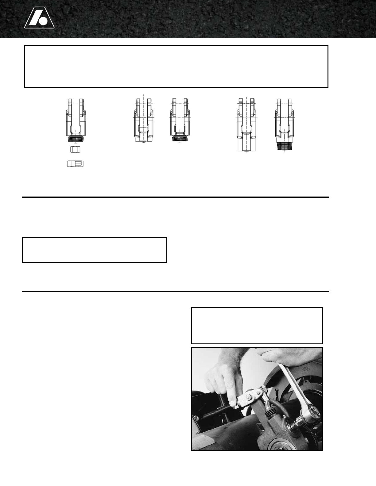
5. Thread the 1-1/4" collar nut
onto the clevis and install
the template over the large
and small pins as shown in
Figure 3.
6. Align the slack by
adjusting the 3/4" hex
nut on the push rod until
the proper centering hole
aligns with the center hole
on the camshaft.
7. Once the slack is properly aligned, tighten the 1-1/4" collar nut
to the clevis using 40 to 50 ft. lbs. of torque.
8. After tightening the 1-1/4" collar lock nut, tighten the 15/16"
jam nut against the collar lock nut using 40 to 50 ft. lbs.
torque.
9. Next follow the instructions in the installation check section
below.
NOTE:
Failure to tighten the jam nut will allow the air chamber
push rod to rotate in the clevis and change the installed
position of the slack, preventing proper automatic adjuster
function.
1. Apply anti-seize compound to the air chamber push rod.
Install the new clevis on the air chamber push rod in the
same location as the clevis which was removed. Do not
tighten the jam nut at this
time.
2. Insert the clevis pins into
the threaded clevis. Install
the template over the
small and large pins as
shown in Figure 4. Align
the slack by adjusting
the clevis in or out on the
push rod until the hole at
the bottom of the template
aligns with the center hole
on the camshaft.
3. If the push rod threads
protrude through the clevis opening more than 1/16",
remove the clevis and cut the push rod to length. The push
rod must not be more than 1/8" short of being flush with
the clevis opening. Follow instruction in the service manual
for cutting a push rod to length.
4. If the push rod fails to come within 1/8" of full engagement
with the clevis opening, install a long push rod and cut to
length. On trailer applications, an extended clevis can be used
instead of replacing the push rod. However, you must have at
least 1/2" of thread engagement inside the clevis. If you have
less than 1/2" thread engagement, a new push rod must be
installed.
5. Tighten the jam nut against the clevis housing using 40 to 50
ft. lbs. of torque. Failure to tighten the jam nut now will allow
the clevis to rotate freely and change the position of the clevis
resulting in improper installation.
6. Apply anti-seize to the camshaft and install the slack using
original mounting hardware. Using a wrench or socket,
rotate the hex extension until the holes in the slack housing
align properly with the holes in the clevis. Hold the link (rod
with small 1/4” hole) down while rotating the hex extension
clockwise. Failure to do so can cause the link to disengage
from the drive.
7. Once properly aligned, insert both the large and small clevis
pins and insert the cotter pins.
8. Next follow the instructions in the installation check section
below.
NOTE:
On axles equipped with spring brake chambers, be sure the
chambers are fully caged before cutting the push rod. If the
spring brakes are not fully caged, the push rod can be cut too
short.
NOTE:
Failure to tighten the jam nut will allow the air chamber
push rod to rotate in the clevis and change the installed
position of the slack, preventing proper automatic adjuster
function.
Installation of the Gunite Threaded Clevis and Extended Threaded Clevis
Figure 3 -
Gage Location
Figure 4 - Gage Location