Acer A221HQV User manual

Model ID: RG215AC-CAU-AN02
ACER_LCD_A211H/A221HQ_SM20100512V1

Contents
ACER_LCD_A211H/A221HQ_SM20100512V1
ACER A211H/A221HQ
Table of Contents
Important Safety Notice------------------------------------------------------------------------------------- 01
01. Product Specification--------------------------------------------------------------------------------- 02
02. OSD Menu-----------------------------------------------------------------------------------------------10
03. Exploded Diagram------------------------------------------------------------------------------------- 12
05. Troubleshooting----------------------------------------------------------------------------------------21
08. Block Diagram------------------------------------------------------------------------------------------ 62
Appendix I : User’s Manual
04. Assembly and Disassembly Procedures-----------------------------------------------------------14
06. Firmware Upgrade Procedure------------------------------------------------------------------------58
07. Writing EDID Procedure-------------------------------------------------------------------------------60
Appendix II : User’s QSG
Appendix III : Spare Parts List
Appendix IV: Software Pack
Safety Notice
Any person attempting to service this chassis must familiarize with the chassis and be
aware of the necessary safety precautions to be used when serving electronic equipment containing
high voltage.

Go to contents page
Product Announcement:
This product is certificated to meet RoHS Directive and
Lead-Free produced definition. Using approved critical
components only is recommended when the situation
to replace defective parts. Vender assumes no liability
express or implied, arising out of any unauthorized
modification of design or replacing non-RoHS parts.
Service providers assume all liability.
Qualified Repairability:
Proper service and repair is important to the safe,
reliable operation of all series products. The service
providers recommended by vender should being
aware of notices listed in this service manual in order
to minimize the risk of personal injury when perform
service procedures. Furthermore, the possible existed
improper repairing method may damage equipment or
products. It is recommended that service engineers
should have repairing knowledge, experience, as well
as appropriate product training per new model before
performing the service procedures.
NOTICE:
!To avoid electrical shocks, the products should be
connect to an authorized power cord, and turn off the
master power switch each time before removing the
AC power cord.
!To prevent the product away from water or explosed
in extremely high humility environment.
!To ensure the continued reliability of this product,
use only original manufacturer’s specified parts.
! To ensure following safety repairing behavior, put the
replaced part on the components side of PWBA, not
solder side.
! To ensure using a proper screwdriver, follow the
torque and force listed in assembly and disassembly
procedures to screw and unscrew screws.
Using Lead-Free solder to well mounted the parts.
!The fusion point of Lead-Free solder requested in the
degree of 220°C.
!
Important Safety Notice 3
1
ACER A211H/A221HQ

This LCD monitor includes an interface board, a power
board and a function key board.
The interface board controls the TFT panel control logic,
brightness control logic, and DC-DC conversion to supply
the appropriate power to the whole board and LCD panel.
The LVDS signals transmit video data to LCD Module to
drive the LCD display circuit.
The power board will provide the DC power to the interface
board, LCD panel and inverter board.
The function key board is used for OSD control, monitor
power ON/OFF and the LED indicator for power status.
This monitor meets Energy Efficiency grade 2 of China.
1.2 General Requirements:
1.2.1 Test Condition:
Normal test condition is that brightness level set at
Max. and contrast level set default. Test pattern is full
white pattern. The warm up time is more than 30
minutes. Ambient light should be less than 1 Lux.
1.2.2 Test Equipment:
The reference signal source is a calibrated Chroma
2326 or Quantum 801GD video generator. The use of
compatible generators during qualification and
production is acceptable.
Luminance meter is Minolta CA210, TOPCON BM7 or
compatible equipment.
1.3 Electrical:
This section describes the electrical requirement of the
monitor. Below is the block diagram.
This model combine with three platforms. See below
explanation.
1. Scaler IC: RTD2482D used in VGA, DVI and HDMI port.
Using simply word to define it.(1A1D1H)
2. Scaler IC: RTD2281 used in VGA and DVI port. Using simply
word to define it.(1A1D)
3. Scaler IC: RTD2280L used in VGA port. Using simply word to
define it.(1A)
1.1 Scope:
This document defines the design and performance
requirements for the 21.5” wide flat panel monitor. The
display elements shall be a 21.5” inch diagonal, UXGA
(1920 x1080) resolution TFT-LCD display .Video input
signals include D-sub and digital DVI-D , HDMI and
DP(DisplayPort) depends on different model. Power saving
function complies with the VESA DPMS (Display Power
Management Standard).
General display parameters:
1. Product Specification
LCD Flat Panel
Interface Board
Flat Panel Controller,DDC
Power Board
AC to DC Adapter
DC to AC Inverter
Audio
AMP
(Option)
AC-IN
1W*2
Speaker
(Option)
Audio Source Host Computer Function Key
Board
CCFL
Panel data & control. DC power
Speaker
line input
DC 5V
Audio line input
Video Signal input& DDC Function key input
Display Area 21.5” diagonal
476.64mm(H)x268.11mm(V)
Resolution 1920 x 1080 pixels
Display Color Number 16.7M colors(6bit Hi FRC)
Display Type a-Si TFT active-matrix
Contrast Ratio 1000 : 1 typ.
Brightness 250cd/m2 typ.
Response Time (Ton + Toff) 5 ms typ.
Pixel Pitch 0.248mm(H) x 0.248mm(W)
Vertical Viewing 160 degrees typ, CR>10
Horizontal Viewing 170 degrees typ, CR>10
SPEC
H 31kHz ~ 82kHz
V 56Hz ~ 75Hz
Max Pixel clock 210MHz
Video input 0.7Vp-p
RGB Input Impedance 75Ù
Sync Input Signal Separate SYNC, Composite Sync
Sync Input Impedance 2.4KÙ(1A1D1H), 50Ù(1A1D/1A)
H 31kHz ~82kHz
V 56Hz ~ 75Hz
Max Pixel clock 165MHz
Input Level 150mV<=Vp-p<=1560mV
Input Impedance Input Impedance 100Ù per pair
AC power AC 100V ~ AC 240V ± 10% 50/60Hz,
3 pin AC power cord
Input connectors D-SUB 15pin, DVI-D 24pin, HDMI
19pin
Audio Jack (OPTIONAL) Audio input 3.5Ö
AC IN 100~240V
Normal Operation
Power Saving < 1W
Power Off < 1W (90VAC~264VAC)
User’s Control Front Panel Buttons Right, Left, MENU, AUTO,E,Power
Preset Timing 13
User’s Timing 9
VESA DDC2B
VESA DPMS
H±1kHz, V ±1 Hz
Pre-Defined Timing
Power Saving
Input Signal Counter tolerance
Plug and Play
Connectors
Power Consumption
30W Max(with audio)
35%typical, 65%min
Dimming control range
(max-min/max) x100%
ITEM
Frequency Ranges
Analog Signal Input
(VGA)
Digital Signal Input
(DVI&HDMI)
Frequency Ranges
2
Go to contents page
ACER A211H/A221HQ

1.3.1 Interface Connectors:
1.3.1.1 Power Connector and Cable:
The AC inlet connector shall be an IEC/CEE-22
type male power receptacle for connection to
mains power. The power cord shall be black/white
depending on the color of machine with length of
1.8±0.05 meters. The power cord type is different
from regions.
1.3.1.2 Analog Connector and Cable:
These signal input connector shall be 15 D-sub
capable of receiving VGA analog signal. The VGA
signal cable shall be black and with length of
1.8meter. The D-sub cable shall be a molded-
over, shielded, triple row, 15 pins and blue color D
type connector.
1.3.1.3 DVI-D digital Connector and Cable:
These signal input connector shall be 24 DVI-D
capable of receiving TMDS digital signal. The DVI
cable shall be black and with length of 1.8meter.
The DVI cable shall be a molded-over, shielded,
triple row, 24 pins, and white color DVI-D
connector.
1.31.4 HDMI digital video and audio Connector and
Cable:
These input connector shall be capable of
receiving digital video and audio signal per HDMI
requirement. The optional HDMI cable shall be
black and with length of 1.8 meter.
Connector Pin Assignment:
B. DVI-D (Digital TMDS) Connector
A. D-SUB
1. (continued)Product Specification
C. HDMI Connector
D. Flat Panel Connector
Pin Signal Description
1 Red-Video Red video signal input
2 Green-Video Green video signal input
3 Blue-Video Blue video signal input
4 GND Ground
5 Self Test Detect VGA Cable have connected or not
6 Red-GND Analog signal ground for the Red video
7 Green-GND Analog signal ground for the Green video
8 Blue-GND Analog signal ground for the Blue video
9 + 5V +5 input from host system for the VESA DDC2Bi
function
10 DDC-GND Signal ground
11 GND Ground
12 DDC-SDL SDA signal input for the VESA
DDCB2i function
13 H-SYNC Horizontal signal input from host system
14 V-SYNC Vertical signal input from the host system
15 DDC-SCL SCL signal input for the VESA DDC2Bi function
PIN NO SYMBOL FUNCTION
1 RXOIN0- Negative LVDS differential data input(Odd Data)
2 RXOIN0+ Positive LVDS differential data input(Odd Data)
3 RXOIN1- Negative LVDS differential data input(Odd Data)
4 RXOIN1+ Positive LVDS differential data input(Odd Data)
5 RXOIN2- Negative LVDS differential data input(Odd Data,
DSPTMG)
6 RXOIN2+ Positive LVDS differential data input(Odd Data,
DSPTMG)
7 GND Power Ground
8 RXOCLK- Negative Sampling Clock input (ODD clock)
9 RXOCLK+ Positive Sampling Clock input(ODD clock)
10 RXOIN3- Negative LVDS differential data input(Odd data)
11 RXOIN3+ Positive LVDS differential data input(Odd data)
12 RXEIN0- Negative LVDS differential data input(Even data)
13 RXEIN0+ Positive LVDS differential data input(Even data)
14 GND Power Ground
15 RXEIN1- Negative LVDS differential data input(Even data)
16 RXEIN1+ Positive LVDS differential data oinput(Even data)
17 GND Power Ground
18 RXEIN2- Negative LVDS differential data input(Even data)
19 RXEIN2+ Positive LVDS differential data input(Even data)
20 RXECLK- Negative Sampling clock input(Even clock)
21 RXECLK+ Positive Sampling clock input(Even clock)
22 RXEIN3- Negative LVDS differential data input(Even data)
23 RXEIN3+ Positive LVDS differential data input(Even data)
24 GND Power Ground
25 NC No connection(For AUO test only. Do not connect)
26 NC No connection(For AUO test only. Do not connect)
27 VDD
28 VDD
29 VDD
30 VDD
Power Supply: +5V
Pin Signal Pin Signal
1 TMDS Data 2+ 11 TMDS Clock Shield
2 TMDS Data 2 Shield 12 TMDS Clock-
3 TMDS Data 2- 13 CEC
4 TMDS Data 1+ 14 Reserved
5 TMDS Data 1 Shield 15 SCL
6 TMDS Data 1- 16 SDA
7 TMDS Data 0+ 17 DDC/CEC Ground
8 TMDS Data 0 Shield 18 +5V Power
9 TMDS Data 0- 19 Hot Plug Detect
10 TMDS Clock+
Pin Signal Pin Signal
1 TMDS Data 2- 13 NC
2 TMDS Data 2+ 14 +5V POWE R
3 TMDS Data GND 15 Self Test
4 NC 16 Hot Plug Detect
5 NC 17 TMDS Data 0-
6 DDC Clock 18 TMDS Data 0+
7 DDC Data 19 TMDS Data GND
8 NC 20 NC
9 TMDS Data 1- 21 NC
10 TMDS Data 1+ 22 TMDS Clock GND
11 TMDS Data GND 23 TMDS Clock +
12 NC 24 TMDS Clock -
3
Go to contents page
ACER A211H/A221HQ

Go to contents page
1.3.2 Input Signals:
1.3.2.1 Video Signal Amplitudes:
The video inputs consist of Red, Green and Blue
signals each has its own coaxial cable terminated
at the monitor. These video signals are analog
levels, where 0V corresponds to black, and
700mV is the maximum signal amplitude for the
respective color. The video signal is terminated
with 75 ohms.
1.3.2.2 Video Signal Termination Impedance:
The analog video signal termination shall be 75
ohm +/- 2%.
1.3.2.3 Synchronization (Sync) Signals:
The Horizontal Sync (HS) TTL signal is used to
initiate the display of a horizontal line. HS may be
either active high or active low according to the
timing. The Vertical Sync (VS) TTL signal is used
to initiate the display of a new frame. VS may be
either active high or active low according to the
timing.
1.3.2.4 Sync Signal Levels:
The monitor must accept sync signals from both
3.3 and 5 volt TTL logic families. The inputs shall
sense a logic 0 when the input is 0.8 volt or less
and shall sense a logic 1 when the input is 2.0
volts or greater. In addition to these level
requirements, there shall also be a minimum of
0.3 volt hysteresis provided for noise immunity
(typically by using a Schmitt Trigger input). That
is, the input level at which the monitor actually
detects a logic 0 shall be at least 0.3 volt lower
than the level at which it actually detects a logic 1.
If the monitor sync processing circuits were
designed with 3.3 volt logic family, then the sync
inputs must be 5 volt tolerant.
1.3.2.5 Sync Signal Loading:
TTL input loading shall be equivalent to one TTL
input load. When logic 0 is asserted by a sync
input, the maximum current source from any
single monitor sync input to the driver is 1.6 mA.
When logic 1 is asserted, the maximum current
source from the driver to any single monitor sync
input is 400 uA.
1.3.2.6 Abnormal Signal Immunity:
The monitor shall not be damaged by improper
sync timing, pulse duration, absence of sync,
abnormal input signal amplitude, or any other
anomalous behavior of a graphics card.
1. (continued)Product Specification
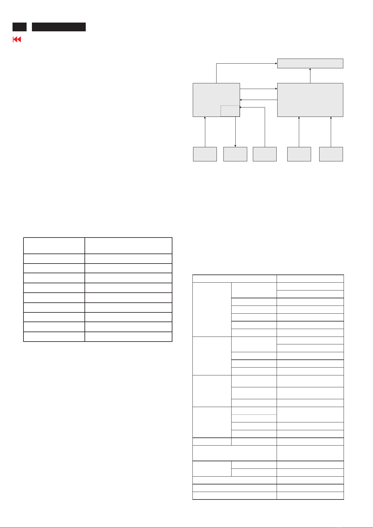
1.3.3.3 On-Screen Display:
On Screen Display system shall be used to
control the monitor. Current setting will be saved
and OSD will be tuned off when the keys are not
touched for a period of time. (Please see OSD
timeout section)
A) Key Function Overview: All functions are
controlled by OSD buttons on the front cover.
Press the function button to open the shortcut
menu. The shortcut menu lets you quickly select
the most commonly accessed settings.
1.3.2.7 Digital TMDS Input (DVI and HDMI signal input):
These video inputs consist of TX0+/- to TX2+/-±
and CLK+/- signals, each with its own shielded
twisted pair. These video signals are digital levels.
Each signal pair is terminated by a normal 100
ohms.
1.3.2.8 Audio Function (optional):
This monitor integrated with stereo audio.
Speakers: 2 x 1W
Amplifier: Output 1W with 500mVrms Sine wave
input.
Input impedance: >22K Ohms.
THD: <10%.
1.3.3 User Controls and Indicators:
1.3.3.1 Power On/Off Switch:
The monitor shall have a power control switch
visible and accessible on the side of monitor.
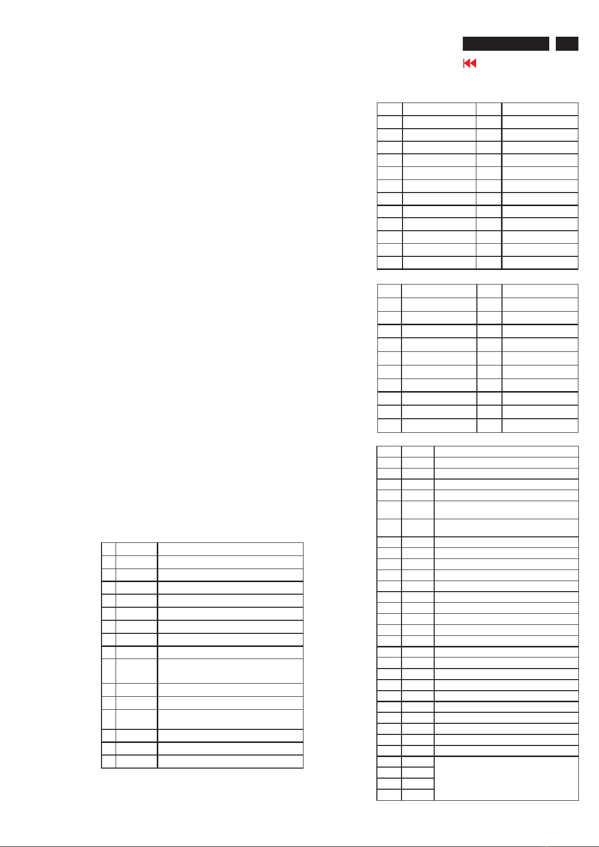
1.3.3.2 Power Indicator LED:
The monitor shall have LED indicators located on
the front of the monitor. Table 1 is the LED color
for the power indicator.
B) Menu Operation:
Pressing the MENU button brings up the first level
menu. This menu button is used to enter the
second OSD menu also.
LED Color
Power-ON Mode: Blue
Power Saving Mode: Amber
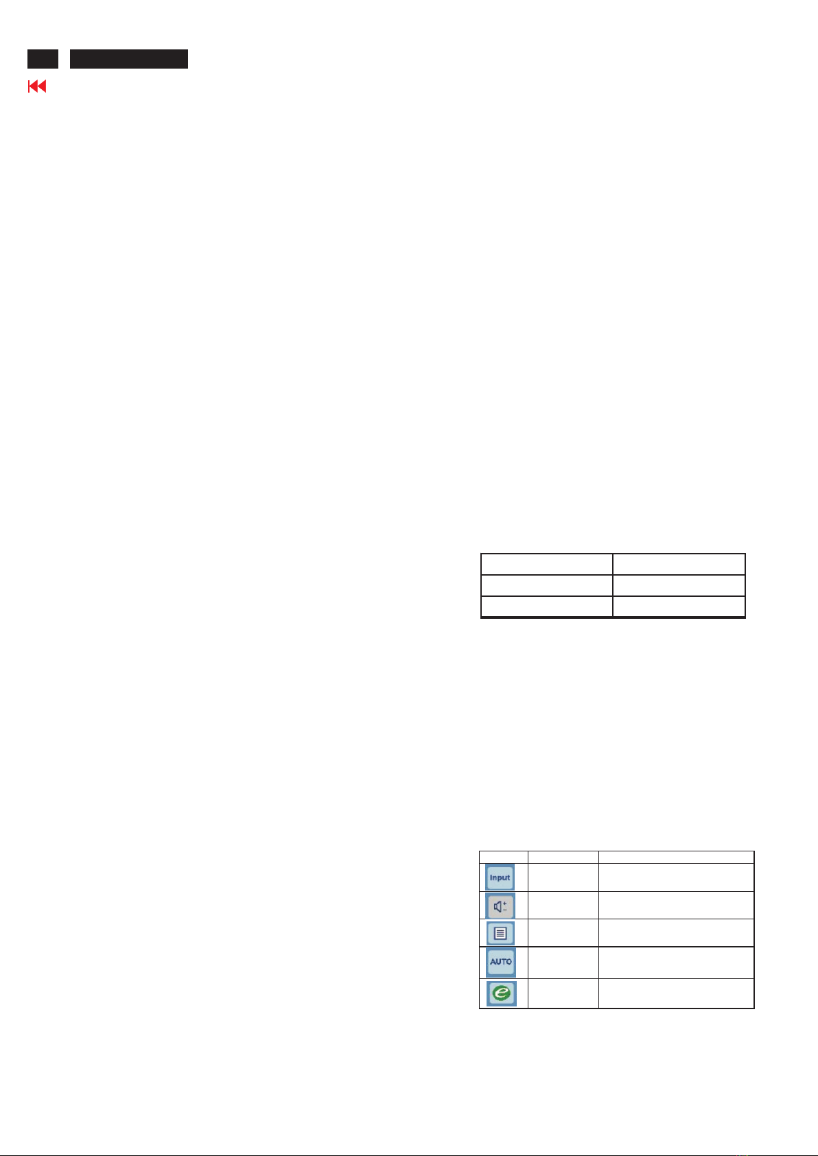
Shortcut menu Content OSD Display
Input change function Use Input key to select from different video
sources that may be connected to your monitor.
Speaker Volume
control function Press this button to activate the Volume menu.
OSD Function Press this button to activate the OSD menu.
Auto Adjust Function
Press this button to activate the Auto Adjustment
function. The Auto Adjustment function is used
to set the HPos, VPos, Clock and Focus.
Empowering
Press the Empowering Key to open the Acer
eColor Management OSD and access the
scenario modes.
4ACER A211H/A221HQ

Go to contents page
monitor shall display a warning screen indicating
that the input frequency is out of range. Under no
circumstances shall any combination of input
signals cause any damage to the monitor.
1.3.4.2 Factory Assigned Display Modes:
There are 13 factory pre-set video modes. Pre-
defined mode parameters will be recalled if the
operating mode is one of those pre-set modes. If
the operating mode is not one of those stored in
memory, the monitor CPU will select the PRESET
timing for a mode that is the next lowest in
horizontal scanning frequency The screen
parameters can be adjusted by the front bezel
control buttons and then saved as a user defined
mode. The monitor shall include all the preset
video timings shown in the following page.
1. Product Specification (continued)
D) OSD Control Factory Default Values:
The OSD controls shall have the following factory
default values:
Brightness: 77
Contrast: 50
Color Temperature:
Warm(6500)/Cool(9300)/User (R/G/B all are 100)
Horizontal Position of Screen: 50
Vertical Position: 50
OSD Time: 10 seconds
OSD Language: English
1.3.4 Monitor Modes and Timing Capability:
1.3.4.1 Format and Timing:
The monitor shall synchronize with any vertical
frequency from 55 to 76 Hz, and with any
horizontal frequency from 30 to 83 KHz for analog
input and from 30 to 83 Khz for DVI input. If the
input frequency is beyond the specified range, the
C) OSD Function:
1.3.4.3 Mode Recognition Pull-in:
The monitor shall recognize preset modes within
a range of +/- 1 KHz for horizontal and within a
range of +/- 1Hz for vertical.
1.3.5 Controller Requirements:
1.3.5.1 General Requirements:
The monitor shall include a controller which is
capable of converting the analog RGB signal or
Preset video timings (digital inputs)
Preset Timing Chart:
Cable Remark
640x480p@59.94/60Hz 59.94/60Hz Cat1
720x480p@59.94/60Hz 59.94/60Hz Cat1
1280x720p@59.94/60Hz 59.94/60Hz Cat1
720x576p@50Hz 50Hz Cat1
1280x720p@50Hz 50Hz Cat1
1920x1080i@59.94/60Hz 59.94/60Hz Cat1
1920x1080i@50Hz 50Hz Cat1
1920x1080p 50Hz Cat2
1920x1080p 59.94/60Hz Cat2
Primary Video Format Timings
CEA
Timming
ITEM Content
Volume To increase or decrease the sound level
Brightness Adjust backlight luminance of the LCD panel
Contrast Adjust gain of R,G,B signal
Clock Adjust the ratio of dividing frequency of the dot clock
Focus Adjust the phase of the dot clock
H.Position The active screen is horizontally move right and left
V.Position The active screen is vertically move up and down
Color temp Select three kinds of modes(Warm, Cool, User)
1.USA-select the language among English, French,
Italian, Deutsch, Spanish, 繁體中文, 簡體中文, 日本語
2.EMEA-select the language among English,
French,Italian, Deutsch, Spanish, Russian, Dutch,
Finnish
OSD Position Adjust the OSD menu position
OSD Timeout The OSD menu show time
Setting The setting of Input Source, Wide Mode, DDC/CI
Information It will show resolution, the frequency of
horizontal/vertical synchronizing and S/N
Reset All data copy from shipment factory data
OSD
Language
Power
Saving Mode
Menu
This function gives a warning message when selected input
signal is not active. When the Monitor detected that the VGA
or DVI is suspend or standby mode. The Moni tor shall display
a message, “No Signal” for 4 seconds and the LED shall be
blue, and to alert the user that input signal is not active.
Then the monitor shall go into sleep mode and the LED shall
be Amber.
Out of
range Menu
This function gives warning message about input resolution or
refresh rate that the monitor cannot support. When an input
signal which is out of the normal operation range defined in
Section 3.2. Then the monitor will display “Input not supported”
mess age:
1. Pixel clock frequency : Fc>165(Digital)
Fc>205 (Analog)
2. V-sync frequency: 50Hz>FV>=76Hz
3. H-sync frequency: 30KHz>FH>83KHz(Analog);
30KHz>FH>83KHz(Digital)
Check Signal
cable Menu
This function gives warning message when the VGA cable is
not connected. When the Monitor detected that the VGA cable
is not connected to the monitor. The OSD s hall display a
mess age “Cable not connected” all the time to alert the user
that the video cable is not plugged in. The LED shall be blue.
The monitor shall use a method of a pull-up resistor on a
ground pin to determine if the video cable is connected to
the PC.
Resolution Horizontal Vertical Nominal Pixel User Manual
(active dot) Frequency
(KHz)
Frequency
(Hz) Clock (MHz) description
640x480@60Hz 31.469 59.941 25.175 Yes Established Timing
640x480@72Hz 37.861 72.809 31.5 No N/A
640x480@66.66Hz 35 66.66 30.24 Yes Established Timing
720x400@70Hz 31.469 70.087 28.322 Yes Established Timing
800x600@56Hz 35.156 56.25 36 Yes Established Timing
800x600@60Hz 37.879 60.317 40 Yes Established Timing
800x600@72Hz 48.077 72.188 50 No N/A
1024x600@60Hz 37.32 60 48.964 No N/A
1024x768@60Hz 48.363 60.004 65 Yes Established Timing
1024x768@70Hz 56.476 70.069 75 Yes Established Timing
1152x864@75Hz 67.5 75 108 Yes Standard Timing
1280x960@60Hz 60 60 108 No N/A
1280x1024@60Hz 63.981 60.02 108 Yes Standard Timing
1280x720@60Hz 44.76 60 74.481 No N/A
1280x800@60Hz 49.702 59.81 83.5 Yes Standard Timing
1360x768@60Hz 47.712 60.015 85.5 No N/A
1440x900@60Hz 55.935 59.887 106.5 Yes Standard Timing
1680x1050@60Hz 65.29 59.954 146.25 No N/A
1600x1200@60Hz 75 60 162 No N/A
1920x1080@60Hz 67.158 59.963 173 Yes Standard Timing
1920x1080@60Hz 67.5 60 148.5 Yes Detail timing
1920x1080@60Hz 66.587 59.934 138.5 No
EDID
5
ACER A211H/A221HQ

DVI digital signal to the panel. The controller will
include a PLL, A/D converters, TMDS receiver
and other circuitry necessary to perform its
function. The PLL shall be stable enough to
ensure a stable image.
1.3.5.2 Video Stretching:
The monitor shall have the function to “stretch”
the video signal, so that an input signal from the
computer in any resolution smaller than 1920 x
1080 is automatically expanded to fill the entire
screen.
1.3.5.3 Panel Timing and Interface:
The controller supplied with the monitor shall
control all panel timing. This controller shall
adequately insulate themonitor from the
computer, so that no possible combination of
input signals from the computer shall cause
damage to the flat panel or any other component
of the monitor.
1.3.6 DC - AC Inverter Requirements:
The frequencies used by the DC - AC inverter should be
carefully selected to prevent any noticeable effects on the
screen (such as a rolling effect). The Inverter
specification detail information in Table 2:
1. Product Specification (continued)
1.3.8 Display Communications Channel:
The monitor shall provide a display communications
channel that conforms to VESA DDC2B hardware
requirements. This configuration shall contain the
128-byte EDID file as specified by VESA E-EDID
Standard. Once the EDID is programmed the write
protection function will enabled. So the EEPROM
data cannot be overwritten.
1.4 Flat Panel:
1.4.1 General Requirements:
The panel shall be a Full HD resolution 21.5”
diagonal TFT-LCD.
1.4.2 Panel Timings:
The controller in the monitor shall translate video
timings from the PC to meet the timing requirements
listed in Panel specification. Under no circumstances
may the controller supply the panel with timings that
may result in damage. The controller shall insulate
the panel from the PC, so that the panel shall always
be driven according to its specification regardless of
the timings being sent from the PC.
1.4.3 Polarizer Hardness:
The outer face of the front polarizer panel shall be
covered with a coating with a 3H hardness value.
1.4.4 Backlight Requirements:
The backlight assembly shall be designed to support
field replacement at the customer site or authorized
service center. The backlight module shall have a
continuous operating life of at least 30,000 hours at
25°C. The operating life is defined as having ended
when the illumination of light has reached 50% of the
initial value. The backlight module shall extend a
sufficient amount from the edge of the light guide that
sputtering over the life of the
backlight shall not cause degradation of the
luminance uniformity (such as non-illuminated bands
along the edges of the display).
1.3.7 Power Supply Requirements:
The AC to DC power supply for this monitor shall be an
integrated power supply. This power supply shall have an
IEC receptacle for mains power input and provide
sufficient power for backlight assembly, interface board
and panel. And it should meet all requirements specified
in the following Table.
Input Voltage Range The operating range shall be from 90 to 264 VA sinusoidal for all
models specified.
Input Frequency Range Input power frequency range shall be from 47 to 63Hz.
Power Consumption
Power consumption for the monitor shall be less than 30W over
the specified voltage and frequency ranges. In power off mode the
power consumption will be less than 1W (at 90VAC~264VAC).
Line Fuse
The AC input shall be fused and become electrically open as a
result on an unsafe current level. The fuse may not be user
replaceable.
Initial Cold Start
The power supply shall start and function properly when under full
load, with worst case conditions of input voltage, input frequency,
operating temperature, and cold backlight lamps.
Inrush Current
The inrush current must be limited to 35A when operated at
120VAC, and 80A when operated at 220VAC. In - rush current is
measured at an ambient temperature of 25°C, with the unit
temperature stabilized in the power - off.
Hot Start Cycle
The power supply shall not be damaged when switched ON
for one second and OFF for one second for seven
consecutive times after operating for one hour at full load,
25°C, and nominal input line voltage.
Under Voltage
The power supply shall contain protection circuitry such that
the application of an input voltage below the minimum
specified in this table shall not cause damage to the power
supply unit nor cause failure of the input.
Line Transient
The power supply shall operate within IEC 801-4 (+/-1KV)
and IEC 801 -5 (+/-2KV) for the domestic U.S. Version. The
UPS power supply shall operate and comply with CE mark.
DC Output 5.15+/-0.2V (1.85A); 22+/-2V (0.75A)
Item Min. Typ. Max. Unit
Output Current 3 7.5 8 mArms
Output Voltage 791 Vrms
Operation frequency 40 55 60 KHz
Striking Voltage --- --- 1780 Vrms
Inverter specification for M215HW01 V7
6
Go to contents page
ACER A211H/A221HQ

1.4.5 Defects:
1.4.5.1 Visual Inspection:
The LCD panel shall be inspected with all pixels
set to white, black, red, green and blue. The color
variation, brightness variation, and overall
appearance must meet the SPEC.
1.4.5.2 Display Degradation:
Over the life of the product, variation of the
parameters specified in Panel specification shall
be maintained within reasonable limits. The panel
must not exhibit any significant defects while in
operation (excluding the lamp operation).
This does not in any way change the warranty
given by the panel manufacturer.
1.4.5.3 Light Leakage:
Except for the active display area, there shall be
no light emission visible from any angle from any
other part of the display. For this test, the ambient
illumination will follow the panel specification 300
to 700 lux.
1.4.5.4 Allowable Defects:
No cosmetic defects are allowed except those
specified below. The conditions of visual
inspections are as follows:
- Viewing distance: 35 ~ 50cm.
- Ambient illumination: 300 to 700 lux.
- Viewing angle shall be at 90 degree.
- Defects not apparent within one minute shall be
ignored.
1.4.5.5 Defect Terminology:
The following gives the descriptive terms used in
classifying defects
Spots or lines that appear dark in the display
patterns and are usually the result of
contamination. Defects do not vary in size or
intensity (contrast) when contrast voltage is
varied. Contrast variation can be achieved
through the use of varying gray shade patterns.
Spots or lines that appears light in the display
patterns. Defects do not vary in size or intensity
(contrast) when contrast voltage is varied.
Contrast variation can be achieved through the
use of varying gray shade patterns.
When the unit lights, lines appear light (white)
Dark Spots / Lines:
Bright Spots / Lines:
Polarizer Scratch:
1. Product Specification (continued)
with display patterns dark and do not vary in size.
Physical damage to the polarizer does not damage the
glass.
When the unit lights, spots appear light (white) with
display patterns dark and do not vary in size. Physical
damage to the polarizer does not damage the glass.
Horizontal or diagonal lines that appear gray with the
display patterns dark and may have resulted from an
“out of control” rubbing process on the polyimide or
“waves” on the BEFs or prism sheets .
The “rainbow“ effect caused by non-uniform cell
thickness.
When the unit lights, variation / non - uniformity(splotch)
appears light (white) with the display and might vary in
size.
When the unit lights, line(s) in the minor (vertical) or
major (horizontal) axis appear dim, but not completely
on or off.
When the unit lights , lines in both the minor and major
axis do not appear.
A sub - pixel (R, G, B dot) stuck off / on (electrical).
1.4.5.6 Smudges, Streaks and Smears:
When viewing the panel oriented so as to maximize
reflected light, there shall be no visible smudging,
streaking, smearing or other non-uniformity from
contaminants, fingerprints, or defects in any of the
visible surfaces. This is independent of whether the unit
is operating or off.
1.4.5.7 Other Defects:
Undefined defects that are considered to be rejectable
by Acer will be reviewed by Wistron as they become
apparent. These panels will be referred to the Wistron
Corporate / Manufacturer Purchasing Agreement for
disposition
1.4.5.8 LCD Inspection:
Put LCD panel on inspection table and illuminate the
panel with a daylight fluorescent lamp located above the
panel surface such that the luminance at the LCD panel
is between 1000 lux. and 1500 lux. Defect limits are
given inTable 4 .
Polarizer Dent:
Rubbing Line:
Newton Ring:
Mottling:
Dim Line:
Cross Lines Off:
Bright/Dark Dot:
7
Go to contents page
ACER A211H/A221HQ

1. Product Specification (continued)
Allowable distance between spots of two sizes is the
minimum separation number for the smaller spot.
Therefore, if there are two spots, 1.30 mm and 0.4
mm in diameter, they must be at least 15 mm apart.
1.5 Optical Characteristics:
1.5.1 Brightness uniformity:
The uniformity is determined by using a photometer
(CA-210) to measure the 9 points luminance in front
of monitor after at least 30 minutes warm up. It shall
be test at 1920x1080/60Hz mode and full white
square pattern with contrast / brightness in default
value. The values specified are at an approximate
distance 20 cm from the LCD surface and at 0
viewing angle.
The 9 test points are defined as below:
Average Diameter
Smaller of (L+W)/ 2 or
L/20 + 2W
Acceptable
Number Minimum Separation
< 0.1mm Non countable N / A
0.1mm - 0.3mm 10 15mm
0.31mm - 0. 5mm 10 15mm
0.51mm - 1.25mm 5 15mm
1.26mm - 2. 5mm 3 25.4mm
2.51mm - 0. 3mm 3 25.4mm
Greater than 3.75mm None Not applicable
Table 4. Desc riptiv e Terms
The brightness uniformity is calculated as below:
Brightness uniformity >= 75%
Remark: The black luminance non-uniformity are no
defined by panel spec, therefore, we don't define the
spec. for black luminance non-uniformity.
Tr + Tf : 5 msec typ.
Remark: Optical response time vs gray scale.Test
condition: brightness set to max, and contrast set to
default.
1.5.4 Viewing angles:
The viewing angles are measured at CR >=10 as below :
1.5.2 Contrast ratio (CR) :
1.5.2.1 General CR:
The contrast ratio is determined by using a photometer
(CA-210) to measure the maximum and minimum
luminance in front of monitor after at least 30 minutes
warm up. It shall be test at 1920x1080/60Hz mode
and full white/full black square pattern with
contrast/brightness in default value. The values
specified are at an approximate distance 20 cm from
the LCD surface and at 0 viewing angle.
The contrast ratio is calculated as below:
CR=(Max. full white luminance)/(Max. full black
luminance)
CR = 600:1(min.), CR=1000:1(typ.)
1.5.2.2 ACM (Auto Contrast Management):
The input image signal source may be various levels
of illumination, and this ACM unit can analyze it as
histogram for the various levels of illumination,
according to the analyzed result, when input a low-
luminance level image, display brightness will be
adopted to corresponding low level, so that enhance
the contrast rate, this facilitates visual ergonomics
enhancement .
The monitor should me CR >50000:1 when ACM
function is active.
1.5.3 Response time:
The response time is defined as below:
8
Go to contents page
ACER A211H/A221HQ

1. Product Specification (continued)
Horizontal Left: 85 degrees typ.
Right: 85 degrees typ.
Vertical Up: 80 degrees typ.
Down: 80 degrees typ.
1.5.5 Chromaticity:
The color chromaticity is measured by a photometer
(CA-210) at 1920x1080/60Hz mode and full white
square pattern with contrast/brightness in default
value. The x and y co-ordinates for Reddish, Bluish
and User preset mode shall be as below:
1.5.6 Brightness:
The uniformity is determined by using a photometer
(CA-210) to measure luminance on the center of
screen after at least 30 minutes warm up. It shall be
test at 1920x1080/60Hz mode and the brightness and
contrast OSD setting for 100%. The values specified
are at an approximate distance 20 cm from the LCD
surface and at 0 viewing angle. The full screen white
center luminance at User mode color temperature
shall be 250 cd/m²typ. And > 200 cd/m²min. Full
screen black pattern luminance at center should be <
1cd/m².
1.6 Environmental Requirements:
1.6.1 Temperature Ranges:
Operating Temperature: 5°C to 35°C
Shipping Temperature: -20°C to 60°C
Storage Temperature: -20°C to 60°C
1.6.2 Humidity:
Operating (non-condensing): 5% to 90%
Shipping (non-condensing): 5% to 90%
Storage (non-condensing): 5% to 90%
1.6.3 Altitude:
Operating 0 to +12,000 feet [3,658m].
Equivalent to 14.7 to 10.1 psia.
Shipping (Non-Operating) 0 to +40,000 feet
[12,192m].
Equivalent to 14.7 to 4.4 psia.
1.7 Mechanical Specification:
1.7.1 Mechanical Summary Table:
Reddish Preset (6500K):
x=0.313 +/- 0.020
y=0.329 +/- 0.020
Bluish Preset (9300K):
x=0.283 +/- 0.020
y=0.297 +/- 0.020
1.7.2 Stand:
1.8 SHIPPING AND PACKING:
Packaging and wrapping shall be sufficient to protect the
product against damage or loss during shipment from the
supplier to the destination specified in the purchase order.
All packaging materials are subject to be tested and
evaluated. The container loading is 2000sets/40'.
The outside dimension of carton box is
570(L)x114(W)x396(H)mm.
1.7.3 Dimension(cm):
Height (including stand) 370mm
Depth (including stand) 161 mm /52.5mm(without base cover)
Width 511.3mm
Pack Dimensions (H x W x L) 570L)x114(W)x396(H)mm
Packaged Weight 4.95kg
Unpacked Unit Weight 3.49 kg
40” container loading, palletized 2000 units
Maximum Stacking Height 5 layers, 2103 mm
Mounting Method 100 x 100 mm VESA Mount
Attachment Method (4) Screws ,M4 x 10mm flat head Phillips socket
Tilt Range -5+/-1.5 degree, +15+/-1.5 degree
Swivel Range -0degree, +0 degree
Lift Range 0mm
Pivot NO 0degree, clockwise
Stand base(attached or
detached for shipping) detached
Stand Tilt/Swivel/Lift/Torque Backward
Tilt
Backward: 1.4+/-0.3 kgf Backward(pivot): 0kgf
Forward: 1.4+/-0.3 kgf Forward(pivot): 0 kgf
3000 times still within spec
Swivel 0kgf/3500 times still with spec
Upward: 0 kgf/3500 times still within spec
Downward: 0kgf/3500 times still within spec
Pivot 0kgf/3500 times still within spec
Head Unit Squareness |A-B|<= 5.0mm |C-D| <= 5.0mm
Head Unit Stability (Wobble
Resistance) Time <= 5 seconds, Displacement <= 7 mm
Cable Management No
Kensington lock hole Yes
Normal Temperature Drop
Height (Packaged) 760 mm, 30 inches
Cold Drop Height (Packaged)
Sequence 1 corner (Corner: corner2-3-5) -> 3 edges -> 6 sides
Lift
unit: mm
9
Go to contents page
ACER A211H/A221HQ

2. OSD Menu
Non-focus
Item focused
Item selected
Status Display type
Settings Information
Function
Status Picture OSD Setup Information
Non-Focus
Focus
Focus on
Item-page
Picture OSD
2.3.1. OSD layout:
1). Display OSD menu when user press “C” button in
Function Menu.
2). Layout as following figure.
2.2 Key Definition:
2.3 Main OSD Menu:
a. OSD layout for each function page
OSD layout for main menu
Item page for
each function
group
Function Icons
Acer logo
Information Bar
b. Icons introduction
c. Item page status
2.1 Function Menu:
1). Display Function Menu while user press any function
button.
2). Layout as following figure:
2.3.2 Key operation:
a.Key operation at function icon.
Focus at main icons
Focus at item page
c.Key operation at items page, item selected.
Item is selected
b. Key operation at items page, no item selected.
Key Functio n Description
Power Power on/off the monitor
AMove the focus down
B Move the focus up
CEnter to the item page
(It has no function at the information page)
D Exit the OSD menu
E Trigger the Acer eColor Ma nagement
Key Function Description
Power Power on/off the monitor
A Move the focus down
B Move the focus up
C Select function item for adjustment
D Exit from the item page to icon place
E Trigger the Acer eColor Management
Key Function Description
Power Power on/off the monitor
A Increa se the setting va lue for target item
B Descrease the setting vallue for target item
C No function
D Exit from item selected status
E Trigger the Acer eColor Management
Key Function Description
Power Power on/off monitor
A In put Switch
B Volume Management OSD
C Main Menu OSD
D Auto Config
E Trigger the Acer eColor Management
1280x960
H:60KHz
Power
AB
C
DE
S/N: ETLH10W004010 0BBE24300
10
Go to contents page
ACER A211H/A221HQ

2. OSD Menu (continued)
Key Function Description
A Volume up
B Volume down
DClose the Volume OSD
2.5 Volume management OSD:
2.6 Acer logo:
2.7 OSD Message:
When the monitor is turned on, the LOGO will be showed
in the center.
Acer logo
OSD layout for the acer eColor management
OSD layout for volume management
a. Display volume management OSD, when user press “<”
or “>”button on the front bezel.
b. Layout as following figure, key operation at items page.
(No item selected)
2.4 Acer eColor management:
b. Layout as following figure.
a. Display Acer eColor management OSD when user
press “e” button at Function menu or trigger this
function in OSD menu/picture page.
Item Description
Auto Config Please Wait When user press hot key "Auto" will show this message,
and the monitor do the Auto config function.
Input Not Support
When the Hsync F requenc y,
Vsync Frequency or Res olution is out of the monitor support range,
will show this message. The mes sage will be flying.
Cable Not Connected When the video cable is not connected, will show this message.
This message will be flying.
No Signal When the vi deo cable is connected, but there is
no active signal input, will show this message,then enter power saving.
Please Wait
After user trigger the reset function,
system will show this message notice user the reset is in proceedi ng.
11
Go to contents page
ACER A211H/A221HQ

4. Assembly and Disassembly Procedures
Use a Phillips-head screwdriver to tighten one
screw till the interface board and the bracket
chassis base be firmly attached.
(No.1 screw size=M3x6, Torque=6~8kgfxcm)
Place a bracket chassis base on a protective
cushion. Turn over the circuit boards and put them
into the bracket chassis base.
Connect of power board with P301 of
interface board. Connect P003 of power board with
P308 of interface board. Connect function key cable
with P309 of interface board. Connect the speakers’
cable to P001 of power board.
P802
4.1 Assembly procedures:
Fix two speakers on the probes of speaker
holders with caps.
S1
S2
S6
Turn over the bracket chassis module. Use a Hex-
head screwdriver to tighten four screws for locking
the DVI and D-Sub connectors.
Use a
Use a
(No.1~4 screw size=M3x8, Torque=5±1kgfxcm)
(No.5 screw size=M3x8, Torque=5±1kgfxcm)
(No.6~7 screw size=M3x10, Torque=5±1kgfxcm)
Phillips-head screwdriver to tighten one
screw for locking the HDMI or DP connector.
Phillips-head screwdriver to tighten two
screws for locking the AC power outlet.
Locate the function cable and audio cable in
the hooks shown as photo.
key
S5
2
1
3
4
Use a Phillips-head screwdriver to tighten four
screws till the power board and bracket chassis
base be firmly attached.
(No.1 screw size=M4x8, Torque=6~8kgfxcm;
No.2~4 screw size=M3x6, Torque=6~8kgfxcm)
S4
S3
S7
Panel preparation: Examine the panel surface
according to inspection criteria. Turn over the
panel to place the screen faced down for later
assembleing.
S8
3
4
1
2
5
76
1
function key cable
audio cable
P802
P301
function key cable
LVDS Cable
speaker’s cable
P003
P308
P001
P309
14
Go to contents page
ACER A211H/A221HQ

4. Assembly and Disassembly Procedures (continued)
Connect FFC cable to LVDS connector, fix the
cable with double faced adhesive tape which is
sticked on the back of cable.
Place a front bezel on a protective cushion the
bracket chassis module into the front bezel. Adjust
the position of bracket chassis module till it is firmly
attached to the front bezel.
, put
Put the bracket chassis module on the back of
LCD panel module.
S9
S10
S11
S12
Take a function key board, then connect the
function key cable with the function key board.
Locate the function board in the hook of the front
bezel, then fix the function key cable with PVC
tapes.
S13
function key board
function key board
Plug lamp cables to the connectors of power
board, then fix the lamp cables with tapes.
15
Go to contents page
ACER A211H/A221HQ

4. Assembly and Disassembly Procedures (continued)
Put a rear cover on the assembled unit and push
the rear cover on the positions marked as No.1~4 in
priority order for mechanisms engagement.
S14
S17
S15
Assemble
.
the hinge covers as the below picture.
Align the base cover with the stand and push the
base cover towards the top of the monitor for
assembling the base
Lift up the LCD module, check the acer logo if it is
firmly attached to the front bezel, connect a video
cable and power cord with the monitor and turn on
the monitor for functionality check.
S18
S19
Turn off the monitor and remove the video cable
and power cord from the monitor. Stick a screen
protector on the front bezel with adhesive tapes.
S20
1
1
2
2
3
3
4
4
Use a Phillips-head screwdriver to tighten three
screws for fix hinge cover with the hinge.
(No.4 )~6 Screw size=M4x8; Torque=6-7kgfxcm
Use a Phillips-head screwdriver to tighten three
screws for fixing hinge with the rear cover.
(No.1~3 )Screw size=M4x9, Torque=12±1kgfxcm
4
5
6
3
12
S16
Take a arm, then install the arm to the hinge cover
following the direction as the picture below.
Take a EPE bag to cover the LCD monitor, put the
monitor face down on the table.
S21
16
Go to contents page
ACER A211H/A221HQ

4. Assembly and Disassembly Procedures (continued)
Pack with PE bags. Take two
cushion foams to hold the LCD monitor, put the
base and arm on the specific positions as the
below picture. Fix the base with adhesive tapes.
the base and arm
Move the whole unit into a carton and put
accessories including user’s manual, D-Sub
cable, audio cable, DVI cable, power cable and
UK cable on specific positions as the photo below.
Seal the carton.
S25
Depress the release hook as indicated first before
removing the base and follow the arrow direction
to remove it.
S22
S24
S23
Depress the release button as indicated, then
remove the arm follow the arrow direction.
base
arm
USER’S MANUAL
POWER CABLE
AUDIO CABLE
D-SUB CABLE
DVI CABLE
UK CABLE
17
Go to contents page
ACER A211H/A221HQ

4. Assembly and Disassembly Procedures (continued)
Remove two cushion foams, tear off the adhesive
tape, take out the LCD monitor from the EPE bag,
remove the screen protector, then put the LCD
monitor on a protective cushion.
Take out the whole cushion foams from the carton
and remove base and arm.
Take out all accessories including user’s manual,
power cable, D-Sub cable, DVI cable, audio cable
and other packing materials from the carton.
(Note: It depends on whether users return the
accessories.)
Open the carton with a proper tool.
S4
S3
S2
S1
4.2 Disassembly procedures:
Use a Phillips-head screwdriver to remove three
screws for releasing hinge.
(No.4~6 screw size=M4x9, Torque=11~13kgfxcm)
S6
S7
Turn over the LCD monitor to let the screen faced
up. Place a cloth on the panel where you are
working on to protect the panel. Then wedge your
fingers between the front bezel and the panel for
unlocking the mechanisms.
Use a Phillips-head screwdriver to remove three
screws for releasing the hinge cover.
(No.1 Screw size=M4x8; Torque=6-7kgfxcm)
S5
1
3
2
4
56
base
arm
USER’S MANUAL
POWER CABLE
AUDIO CABLE
D-SUB CABLE
DVI CABLE
UK CABLE
18
Go to contents page
ACER A211H/A221HQ
Other manuals for A221HQV
1
This manual suits for next models
2
Table of contents
Other Acer Monitor manuals