Thanks for purchsaing an Acewell ATV/Motorcycle/Scooter computer.
This manual is specifically designed for ACE-3XXX series. The
ACE-3100/3150 does not have any extra LED indicator. The ACE-
37XX/38XX series has 4-8 LED indicators. Different models have
different LED indicators; a fuel meter is optional, ut all other
functions are the same. You may find that the photo has a set of
LED indicators different from your computer; the photo is for
reference only.
ATV Computer
ACE-31xx/37xx/38xx series User's Manual
www.acewell-meter.com
Includes analog and digital tachometer, speedometer(300km/h
maximum), trip meter, odometer, clock, average speedometer,
maximum speedometer, riding timer and cumulativel riding timer.
Computer unit has 4-8 built-in LED for different-purpose indicators.
LCD has 2 rows of digital and one analog bar-graphic tachometer
displays, with blue LED backlight.
Odometer and cumulative riding timer measurements are stored in
memory, even when power is off.
The computer's clock display is always on, even when other
functions are power-off.
Adjustable wheel circumference suitable for all kind of wheels:
setting range of 1-3999 mm setting.
Metric/ British system options.
Waterproof design
FEATURES
SPECIFICATIONS
1 Second
1 Minute
9999H59'
0:00'00"- 99:59'59"
Riding Time
Total Time
SPECIFICATIONS
2.3-300.0KM/h (187.5M/h)
MAX 2.3-300.0KM/h (187.5M/h)
AVG 2.3-300.0KM/h (187.5M/h)
0.0-999.9 Km (624.9 Miles)
0.0 - 999999 Km (0.0- 624999 Miles)
500-11,000 rpm
Bar Tachometer
Odometer
Trip Meter 1&2
Maximum Speed Meter
Speed Meter
SymbolFUNCTION
500 rpm
1 Km or Miles
0.1 Km or Miles
0.1 KM/H or MPH
0.1 KM/H or MPH
0.1 KM/H or MPH
INCREMENTS
+/- 50PPM
+/-1% or
+/- 0.1(KPH/MPH)
+/- 0.1%
+/- 0.1%
+/- 50PPM
ACCURACY
Average Speed Meter
+/-1% or
+/- 0.1(KPH/MPH)
+/-1% or
+/- 0.1(KPH/MPH)
TT
RT
ODO
TRIP 1&2
AVG
MAX
Digital Tachometer
RPM 100-19,900rpm
100 rpm
Shift Warning
Maximum Tachometer
MAX
RPM
RPM 100-19,900rpm
100-19,900rpm
100 rpm
100 rpm
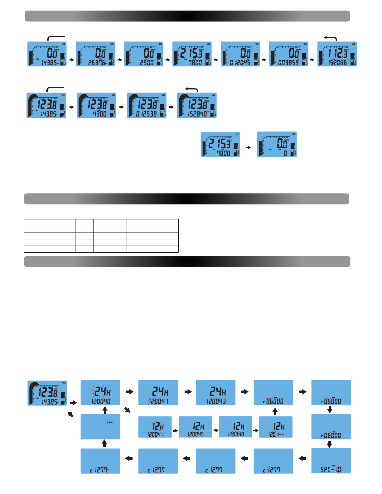
Clock 0:00'00"- 23:59'59" 1 Second /1 Minute +/- 50PPM
Power Input: 12VDC.
Speed Sensor: No Contact Magnetic Sensor.
Tachometer Input: CDI or Ignition-coil signal.
Wheel Circumference setting: 1mm - 3999 mm (1 mm increment)
Operation Temperature: -10°C - +80°C (inner housing)
Storage Temperature: -25°C - +85°C (Inner housing)
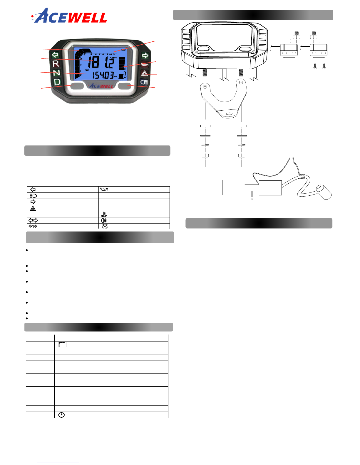
PANEL DESCRIPTIONS
Left-Direction Indicator/Green
Main-Beam Headlamp/Blue
Right-Direction Indicator/Green
Hazard Warning/ Red
Parking/Green
Direction Indicator/Green
Engine Oil / Red
Neutral Gear /Green
Reverse Gear /Red
Drive Gear /Green
Engine coolant temperature/ Red
P
D
R
N
Rear Fog Lamp/Amber
Trailer Flashers/Green
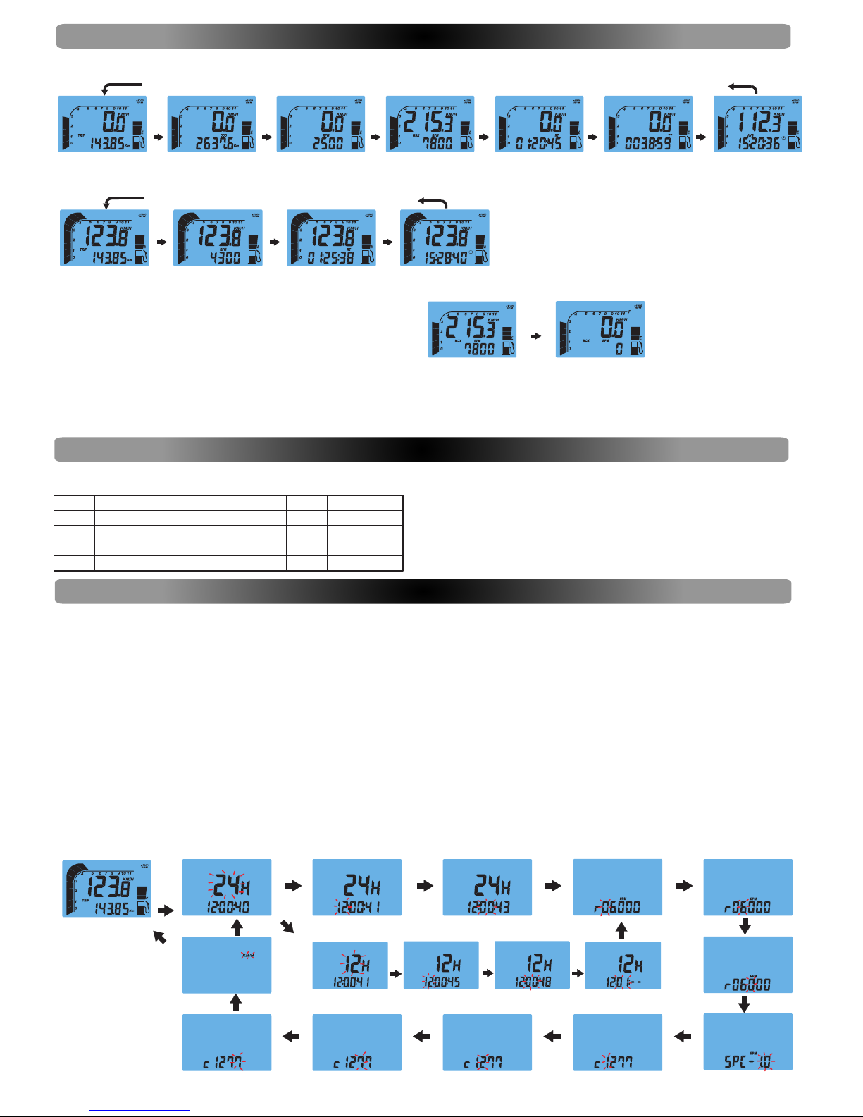
FUNCTIONS
BAR RPM: Bar Graphic Tachometer
1. The bar graphic tachometer reading is always displayed at the bar graph.
2. Tachometer bar graphic displays up to 12,000 RPM.
RPM: Digital Tachometer
1. RPM is displayed in 2nd row.
2. Digital tachometer displays up to 19,900 RPM.
3. Tachometer signal picked up from either CDI or Ignition coil.
Shift Warning RPM
1. Function enables you to set up an RPM shift warning.
2. Bar-graphic tachometer flashes when RPM reaches pre-set value, and stops flashing
after you shift gear.
MAX RPM: Maximum Tachometer
1. MAX RPM is displayed on 2nd row.
2. Displays highest tachometer reading achieved after last RESET operation.
SPD: Speed Meter
1. Speed meter display is on 1st row of the screen.
2. Displays speedometer reading up to 300.0 Km/H or 187.5 mph.
MAX: Maximum Speed Meter
1. MAX is displayed on 1st row.
2. Displays highest speed achieved after last RESET operation.
AVG: Average Speed Meter
1. AVG is displayed on 2nd row.
2. Calculates average speed from last RESET.
TRIP 1 & 2: Trip Meter 1& 2
1. TRIP function registers cumulative trip distance from last RESET while bike is being
ridden.
2. Display is on 2nd row of screen.
ODO: Odometer
1. ODO registers cumulative distance traveled during motorbike operation.
2. ODO data is stored in memory, even when power is off.
RT: Riding Timer
1. Calculates total operation time from last RESET.
2. Count automatically begins with vehicle movement.
TT: Total Riding Timer
1. Calculates total operation time from the beginning of bike use.
2. Count automatically begins with vehicle movement.
3. TT data is stored in memory, even when power is off.
12/24 hour Clock
It displays 12- or 24-hour current time.
Fuel Meter (Only for models with the function)
Has 7 bargraphic indicator of fuel status. Last bar flashes to indicate low fuel level.
INSTALLATION & PARTS
Main Unit Mounting
Speed Sensor & Magnet Mounting
RPM Sensor Mounting
Fixing Screw Nut
Rubber Pad
Washer
Spring Washer
Attention:
1.Align the center of the magnet to
either of the sensor marking line
or the end of the sensor.
2.Installing the sensor parallel to
the vibration direction creates
optimal anti-vibration effect.
3.Make sure the gap between the magnet
and the sensor is within 8mm.
Max8mm
Vibration Direction
sensor
Max8mm
Vibration Direction
sensor
CDI Ignition Coil
RPM-INPUT
Either One
2-5 Turns
2.
1.
3.
4.
6.
5.
8.
1. Tachometer Scale
2. Bar Tachometer
3. 1st row display: Speedometer
and MAX speedometer.
4. 2nd row display: Other functions
5. RESET Button
6. MODE Button
7. Fuel Meter Bar (Optional)
8. LED Indicator symbols
7.
Engine "Not In Use"/Red
Fuel Sensor Resistance: 100Ω(For models with fuel meter only)
1. Signal intensity from ignition coil is dependent on vehicle type.
2. Circles 2-5 turns around ignition coil, with more turns creating steadily
stronger signal, fewer turns creating weaker signal.