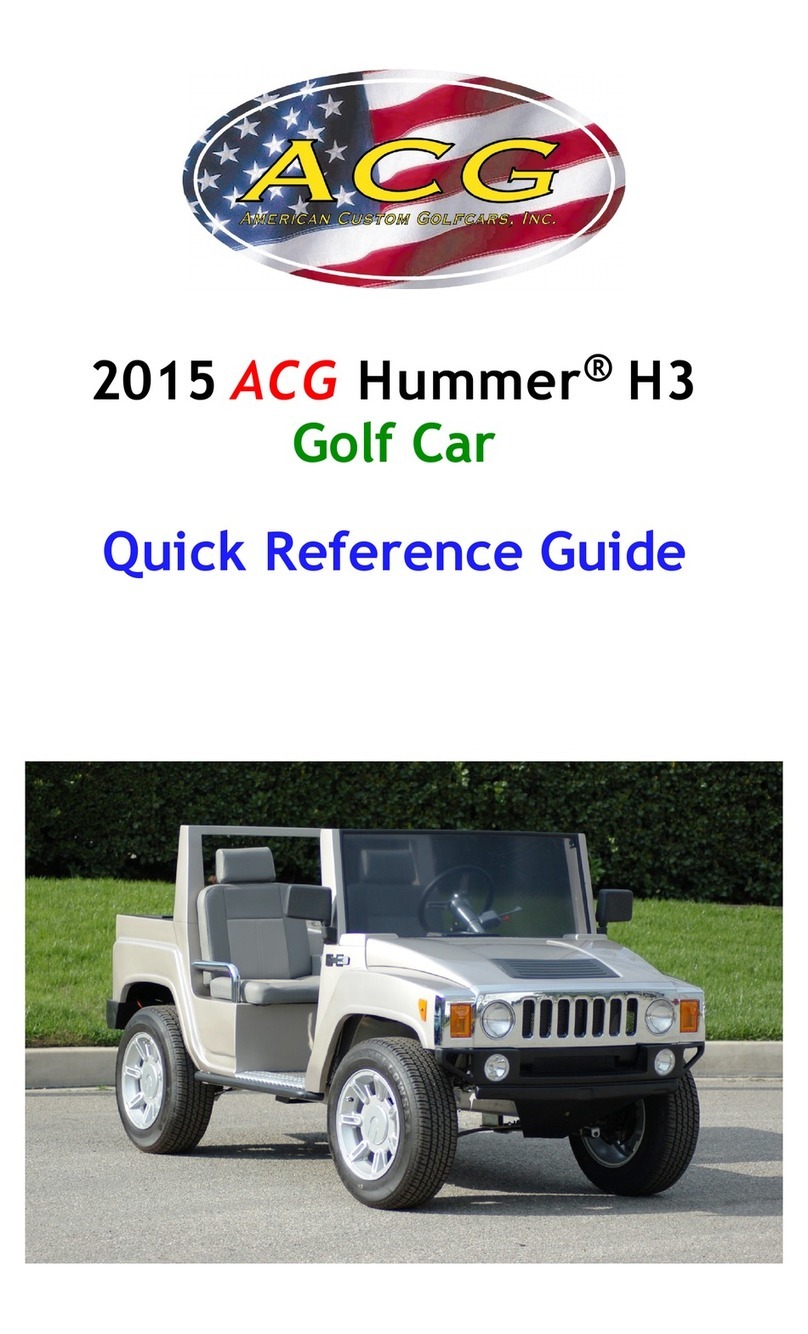
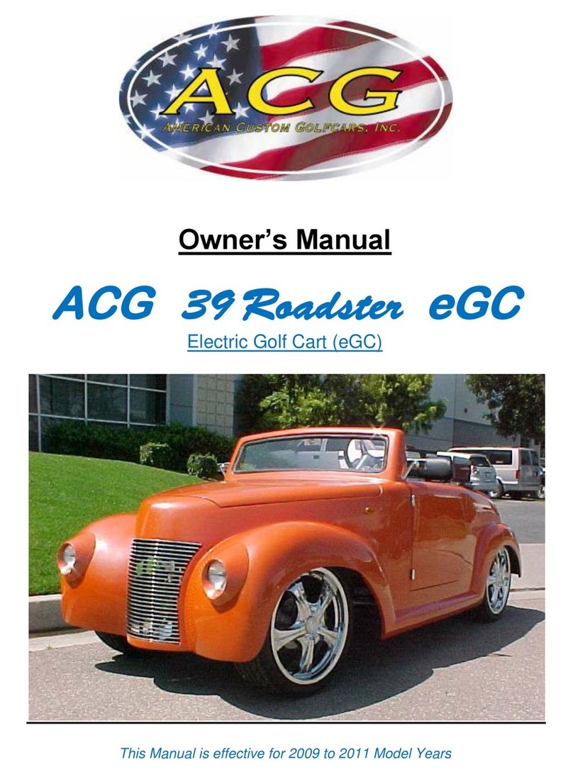
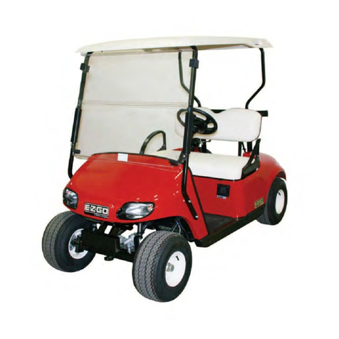
ACG 39 Roadster eGC 2012 User manual

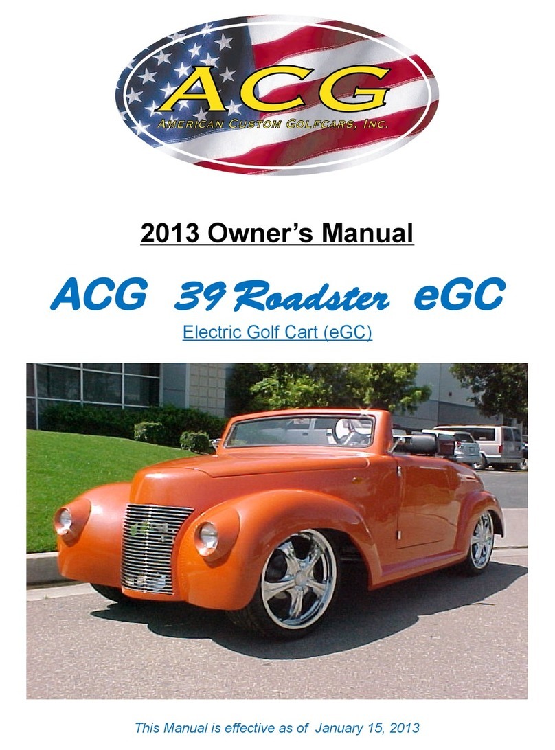
2012 Owner’s Manual
ACG
39 Roadster
eGC
Electric Golf Cart (eGC)
This Manual is effective as of October 1, 2011

Manufactured by:
American Custom Golf Cars, Inc.
(ACG)
15740 El rado Rd.
Chino, CA 91710 USA
(909) 597-2885
(909) 597-7183 fax
www.californiaroadster.com
Copyright © 2009-2011 American Custom Golf Cars, nc.
American Custom Golf Cars, nc., ACG and California Roadster
Are registered trademarks of American Custom Golf Cars, nc.
Copyright © 2009-2011 American Custom Golf Cars, nc. Page 2

Notice
The American Custom Golf Cars, Inc., herein known as ACG, “Limited Warranty”
for owners of the 39 Roadster eGC is included with this manual.
No other warranties, expressed or implied, are contained herein.
ACG and your authorized representative checked this vehicle before it was
delivered to you.
This vehicle does NOT conform to Federal Motor Vehicle Safety Standard FMVSS #500 for
LSV (low-speed vehicles), and is NOT equipped for operation on public streets and roads.
39 Roadster eGC does conform to the current American National Standards nstitute’s
Z130 Safety and Performance Requirements for Golf Cars, as of date of manufacture as
shown on the vehicle’s “Certification Label”.
ACG is not liable for any additional requirements or modifications that your individual state
may require.
ACG is not liable of errors in this manual or for incidental or consequential damages that
result from the use of the material in this manual. The information contained in this
document including the warranty information contained in separate “Warranty” document is
subject to change without notice.
ACG reserves the right to make design and equipment changes to vehicles without
obligation to make these changes on units sold prior to the changes being made.
Throughout this “Owner’s Manual”, the words “golf cart”, “eGC” and “vehicle” are used
interchangeably.
Copyright © 2009-2011 American Custom Golf Cars, nc. Page 3

Table of Contents
Notice…………………………………………………………………………………...... 3
Table of Contents……………………………………………………………………...... 4
Foreword……………………………………………………………………………........ 5
ntroduction…………………………………………………………………………...…. 6
ABOUT TH S MANUAL……………………………………………………………....… 6
nsurance Notice…………………………………………………………………....…… 7
Warranty Registration……………………………………………………………....…… 7
General Warnings…………………………………………………………………....….. 8
SAFE OWNERSH P OF ACG eGC………………………………………………....…. 10
Cautions, Warnings and Notes…………………………………………………….....…11
Controls and ndicators…………………………………………………………..…..…. 12
ey Switch……………………………………………………..…….………...... 12
Forward-Neutral-Reverse Switch……………………………………..….….… 13
Accelerator Pedal……………………………………………..……………..….. 14
Brake Pedal…………………………………………………………..……..…… 15
Park Brake Pedal……………………………………………………..……..….. 15
Light Switch………………………………………………………….………...… 16
Turn Signal Lever Switch…………………………….…………….………...… 17
Hazard Warning Lights Switch……………………………………………....… 18
Turn Signal Directional Indicators…………………………………….....…….. 18
Display Panel……………………………………………………………........… 19
Locking Glove Boxes……………………………………………………….……26
Front Trunk Release…………………………………………………………….. 26
Accessory Outlet………………………………………………..………………..27
Safety Belts……………………………………………………………………………..…28
Tires & Wheels………………………………………………………………………..…. 35
Tire Changing and Jacking Points…………………………………………………..…. 38
Brakes………………………………………………………………………………….…. 39
Pre-Operation and Daily Safety Checklist………………………………………....…. 40
Performance nspection……………………………………………………………........ 41
Driving nstructions………………………………………………………………......….. 42
Starting the Vehicle……………………………………………………….....….. 44
Stopping or slowing the Vehicle…………………………………………......… 44
Parking and Leaving the Vehicle……………………………………….....……44
Batteries…………………………………………………………………………....…….. 45
Battery Care………………………………………………………………...…… 45
Battery Inspection & Maintenance……………………………………....…….. 46
INSPECTION……………………………………………………………..…….. 46
CLEANING……………………………………………………………………….48
WATERING……………………………………………………………….....…. 49
Charging Batteries…………………………………………………………...…. 51
Battery Replacement………………………………………………………...…. 52
Battery Disposal……………………………………………………………........ 52
Periodic Maintenance………………………………………………………………....… 54
DAILY TAS S………………………………………………………………...…. 54
MONTHLY TAS S…………………………………………………………...…. 55
Vehicle Cleaning.......................................................................................... 56
Specifications…………………………………………………………………………..... 59
Copyright © 2009-2011 American Custom Golf Cars, nc. Page 4


Foreword
Thank you for choosing the 39 Roadster eGC for your local and community
transportation needs.
Please protect your investment to make sure that your 39 Roadster eGC will
provide you with years of reliable performance.
Your safety is important to us, so please make sure that prior to operating the
vehicle you have read the following instructions and warnings.
f you rent or loan your vehicle to others, please make sure that they have read this
manual prior to operating this vehicle.
Please consider this manual to be a permanent part of this vehicle and if it is sold,
please make sure that the new owner receives the manual so that they will have the
operating information that it contains as well.
Copyright © 2009-2011 American Custom Golf Cars, nc. Page 5

Introduction
ABOUT THIS MANUAL
Thank you for purchasing your 39 Roadster eGC vehicle manufactured by
American Custom Golf Cars, nc. (ACG)
Your vehicle is designed to operate exclusively on battery power.
t is a “Zero Emission Vehicle” (ZEV).
The ideal application for a battery-powered Golf Cart (eGC) occurs when the daily
driving pattern is predictable and the distance is relatively short.
The ACG company objective includes customer safety and product satisfaction.
This “Owner’s Manual” is designed to acquaint you with the proper and safe
operation of your ACG vehicle.
Please take the time to read and understand the manual before operating your
vehicle.
Maintenance schedules and general care instructions are included in the Operation
and Maintenance section.
This manual is applicable to the following ACG models:
2012
ACG
39 Roadster eGC
f any questions arise after reading the manual, please contact ACG Customer
Service at (909) 597-2885.
Please have your Vehicle dentification Number (V N) and date of purchase
information available.
NOTE:
All information and specifications in this “Owner’s Manual” are current at the time of
printing. However, due to ACG’s policy of continuous product improvement, we
reserve the right to make changes, at any time, without written notice or obligation.
Copyright © 2009-2011 American Custom Golf Cars, nc. Page 6

Insurance Notice
Your Insurance may not provide coverage for accidents involving the use of
this vehicle. To determine if coverage is provided you should contact your
insurance company or agent.
Warranty Registration
The separate “Warranty” document includes a “Warranty Registration Card”.
Your new 39 Roadster eGC (Electric Golf Cart) comes with a One (1) Year
Limited Warranty.
The Warranty begins from the date that the 39 Roadster eGC is purchased from
an approved Dealer or Distributor of American Custom Golf Cars, Inc. products,
provided that the “Warranty Registration Card” is received by American Custom
Golf Cars, Inc. within 45 Days of the purchase date of the vehicle.
f the “Warranty Registration Card” is not received within 45 days of purchase
date, the Warranty commencement date will be the vehicle production date.
lease protect your Warranty and mail your “Warranty Registration Card”
today!
There are no other expressed warranties on your ACG vehicle beyond those set
accompanying “Warranty” document, and no implied warranties of merchantability
or fitness to the full extent allowed by law.
ACG and its dealers shall not be liable for loss of use, inconvenience, lost time,
commercial loss or any incidental, consequential or other damages.
A separate “Tire Registration Card” is provided for Warranty and any potential Tire
Recall campaign, the Tire Registration is required by Federal Law under the TREAD
Act. lease do it today!
Copyright © 2009-2011 American Custom Golf Cars, nc. Page 7

General Warnings _
1. This “Owner’s Manual” should be read completely before attempting to drive or
service the vehicle. Failure to follow the instructions in this manual could result in
property damage, severe personal injury, or death.
2. When charging the vehicle, be sure that the key switch is in the “OFF” position.
f the key is left in the “ON“ position, it may damage the charger or the vehicle.
3. Your vehicle is equipped with an on-board UL- listed charger. When charging
your vehicle, please be sure to use a proper, grounded cord to provide power to
the charger. Please be sure to raise the hood of the golf cart to allow ventilation
of the charger so that it does not overheat.
lease refer to the “CHARGING PROCED RES” manual for further
information on charging of your vehicle.
4. Always obey all traffic regulations when operating the vehicle.
5. When stopping and leaving the vehicle:
a) Make sure vehicle has come to a complete stop.
b) Switch “Forward-Neutral-Reverse Switch” to the “Neutral” position.
c) Engage parking brake
d) Turn the “ ey Switch” to “OFF” position and remove key.
6. Wear safety glasses or approved eye protection when servicing the vehicle.
Wear a full-face shield and rubber gloves when working with the batteries.
7. Use insulated tools when working around batteries or electrical connections.
Use extreme caution to avoid shorting of components or wiring.
8. mproper use of the vehicle or failure to properly maintain it could result in
decreased vehicle performance or severe personal injury.
9. Any modification or change to the vehicle that affects the stability or handling
of the vehicle or increases maximum speed beyond factory specifications, could
result in severe personal injury or death.
10. Prior to servicing Vehicle:
a. Chock the wheels.
b. Turn the “ ey Switch” to “OFF“ position and remove the key.
c. Disconnect battery cables, negative (-) cable first.
Copyright © 2009-2011 American Custom Golf Cars, nc. Page 8

WARNING!
1. f renting or loaning the vehicle, make sure that the driver is familiar with all
controls and operating procedures before allowing the vehicle to be driven.
2. Any modification or change to the vehicle that affects the stability or handling
of the vehicle, or increases maximum vehicle speed beyond factory
specifications, could result in severe personal injury or death.
3. Do not shift the “Forward-Neutral-Reverse Switch” while the vehicle is
moving. To avoid damaging the vehicle or injuring an unsuspecting
passenger, always bring the vehicle to a full and complete stop before
switching from Forward to Reverse.
4. To avoid unintentionally starting or rolling the vehicle:
A). Set the “Parking Brake”,
B). Turn the “ ey Switch” to the “OFF” position,
C). Remove keys prior to leaving the vehicle.
Copyright © 2009-2011 American Custom Golf Cars, nc. Page 9

SAFE OWNERSHI OF ACG ELECTRIC VEHICLES
ACG pure battery electric vehicles are different from vehicles you might be
accustomed to owning. Special precautions should be followed when owning and
operating an ACG vehicle.
Please read this “Owner’s Manual” and pay particular attention to the Cautions and
Warnings in this Manual, as well as those placed on the vehicle in various locations.
n general, ACG Golf Carts are designed and are intended only for use at low
speed, up to 15 mph, and are not intended for use on public roads.
Specific to ACG vehicles, the following safe habits should always be followed:
• ACG vehicles are open vehicles. For this reason, safety belts should always be
worn by all occupants to prevent being thrown from the vehicle during operation.
f your ACG is equipped with optional canvas or plastic doors, these were designed
and are intended only to keep wind and water out of the vehicle and should not be
relied upon to keep occupants in the vehicle or to protect them in case of collision.
• ACG vehicles are not designed to meet any collision or roll-over requirements.
Therefore, you should always drive your ACG vehicle in a safe manner while being
alert to potential dangerous situations around you. As with all motor vehicles, never
drink alcohol and attempt to drive an ACG vehicle.
• Operate an ACG vehicle only on Golf courses or private roads where the speed
limits are appropriate for low speed vehicles and the traffic is light.
(individual state laws vary, so check with your DMV)
• You should never operate an ACG vehicle so that you are an obstacle and
become an annoyance for faster moving traffic.
• ACG vehicles are designed to be recharged from a standard 120 VAC-15 Ampere
electrical outlet that is ground-fault protected. Charging from a circuit of lesser
capacity and/or using a cord from the outlet to the ACG vehicle that is not sufficient
in wire gauge (AWG) could create a fire hazard.
Please consult “Charging Procedures Manual” for the proper extension cord gauge
which depends on its length.
Copyright © 2009-2011 American Custom Golf Cars, nc. Page 10

• The voltage in an ACG vehicle battery pack (the battery pack is what you charge
and provides the “fuel” to the ACG’s electric drive system) is 48 Volt DC and is
sufficient to cause death by electric shock - electrocution.
For this reason, ACG owners should NEVER attempt to do any maintenance or
repair work on their ACG vehicle’s electric drive system, including the battery pack,
unless they have had special training. The one exception is inspection and refilling,
if necessary, of the distilled water in flooded type batteries that can be ordered with
ACG vehicles.
• n this “Owner’s Manual”, the above safe ownership and operation habits will be
pointed out to you as the different aspects of owning and operating an ACG vehicle
are explained. Please read, understand and abide by them for years of safe
operation and enjoyment of your ACG Neighborhood Electric ehicle.
Warnings, Cautions and Notes
Throughout this “Owner’s Manual” you will find the words “WARNING!”
and “CAUTION!” These serve as reminders that attention is required.
“WARNING!”
ndicates an immediate hazard, which could result in an accident
causing bodily injury.
“CAUTION!”
dentifies something that could result in damage to your vehicle.
“NOTE”
Notes are for your information and to make procedures more easily
understood.
Copyright © 2009-2011 American Custom Golf Cars, nc. Page 11

Controls and Indicators
Key Switch
The “ ey Switch” is mounted on the dash to the right of the steering column.
t has two positions:
1. OFF position- There is no power to vehicle. ( ey is Vertical as shown in picture below)
2. ON position- vehicle is ON and can be driven. ( ey is turned clockwise 45 degrees)
ey is shown in OFF position
WARNING!
Never turn the “ ey Switch” to the “OFF” position while the vehicle is
in motion. This could lead to loss of speed control and loss of control
of the vehicle. This can cause a serious accident.
Copyright © 2009-2011 American Custom Golf Cars, nc. Page 12

Forward – Neutral - Reverse Control Switch
The “Forward-Neutral-Reverse Switch” is located on the seat support panel.
There are three (3) distinct positions: Forward, Neutral and Reverse.
1.) FORWARD - To operate the vehicle in the forward direction, rotate the switch
towards the passenger side of the vehicle.
2.) REVERSE - To operate the vehicle in the reverse direction, rotate the switch
towards the driver side of the vehicle. Your Vehicle has been equipped with
a reverse warning beeper so that when the vehicle is in reverse you will hear
a loud beep signaling that the vehicle is in reverse.
3.) NEUTRAL - When the switch is in the straight up and down position the
vehicle is in Neutral and will not move when the accelerator pedal is
depressed.
(Switch shown in Reverse position)
CAUTION!
Always bring the vehicle to a complete stop before changing the
position of the “Forward-Neutral-Reverse Switch”.
Copyright © 2009-2011 American Custom Golf Cars, nc. Page 13

Accelerator edal
The “Accelerator Pedal” is the pedal on the right, with the word “GO” molded into it.
The operation of the accelerator pedal differs from that of an Automobile. When the
“ey Switch” is in the “ON” position, depressing the accelerator pedal will release
the parking brake. As the accelerator pedal is depressed speed will increase until
full speed is reached. When you release the accelerator pedal the power to the
motor is cut OFF and the motor will stop running causing the vehicle to coast.
WARNING!
The vehicle will not stop automatically when the “Accelerator Pedal” is
released. You must depress the “Brake Pedal” in order for the vehicle to
come to a stop or to slow down rapidly.
Copyright © 2009-2011 American Custom Golf Cars, nc. Page 14

Brake edal
The “Brake Pedal” is the large pedal on the left with the word “STO ” molded into it.
To slow or stop the vehicle, release the “Accelerator Pedal” and then depress the
brake pedal with your foot until the vehicle has come to a complete stop or the
vehicle has slowed to your desired speed.
ark Brake edal
The “Park Brake Pedal” is the small raised portion in the upper left corner of the
“Brake Pedal”. t has the word “ ARK” molded into it.
To set the park brake, depress the “Brake Pedal” firmly and tilt the park brake
portion of the pedal forward with your foot.
WARNING!
The “Park Brake” will release automatically when either the “Accelerator
Pedal” or “Brake Pedal” is depressed. The park brake has multiple locking
positions and should be firmly pressed and locked to prevent the vehicle
from rolling.
Copyright © 2009-2011 American Custom Golf Cars, nc. Page 15

Light Switch
The “Light Switch” is located on the Dashboard to the left of the steering Column.
t is identified by SAE/ SO “Lights” icon.
t is a 2 position switch:
1.) OFF - When the top portion of the switch “O” is depressed the lights are “OFF”.
2.) ON - When the bottom portion of the switch “I” is depressed, the lights are “ON”.
(Light switch shown in “OFF” position)
Copyright © 2009-2011 American Custom Golf Cars, nc. Page 16

Turn Signal Lever Switch
The Turn Signals are activated by Lever Switch located on Left side of steering
column below Steering Wheel.
t is a 3 position switch.
1.) RIGHT - When the Lever is pushed UP (Clockwise) – the Right Lights Flash.
2.) OFF - When the Lever is Horizontal, the Turn Signal lights are “OFF”.
3.) LEFT – When the Lever is pushed down (Counter Clockwise) – the Left Lights Flash.
NOTE:
The system DOES NOT have a “self-canceling” feature; return the Lever to the horizontal
“OFF” position after completing the intended Turn or Lane Change!
(Turn Signal Lever Switch shown in “OFF “position)
Copyright © 2009-2011 American Custom Golf Cars, nc. Page 17

Hazard Warning Flashers
The Hazard Warning Flasher Switch activates both Turn Signals to provide
“Hazard Warning” by flashing both Right and Left as well as Front and Rear Turn
Signals at the same time.
The “Hazard” function is activated by Pull Switch located on Left side of steering
column below Steering Wheel. And immediately below the Turn Signal Lever.
t is a 2 position switch.
OFF - When the Pull Switch is released (pushed NWARD)
ON - When the Pull Switch is pulled out, the Turn Signal lights are activated.
NOTE:
The Hazard function can be canceled ONLY by moving the “Turn Signal Lever” from the
the horizontal “OFF” position to either “UP” (Right Turn) or “DOWN” (Left Turn) position!
Turn Signal Directional Indicators
The GREEN LED Light to the Left of the Display Panel will flash when the
Left Turn Signal is activated
The GREEN LED Light to the Right of the Display Panel will flash when the
Right Turn Signal is activated
Copyright © 2009-2011 American Custom Golf Cars, nc. Page 18

Display anel
The 39 Roadster eGC LCD display has following functions:
Battery State of Charge (SoC) shown on bar graph at right of the screen
and as percent % at top of the bar graph (shown above as 88%)
Trip Distance Traveled in miles in NN.N format (shown above as 90.6 mi.)
Odometer TOTAL Distance Traveled in miles in NNNN.N format
(shown above as 231.9 mi.)
Vehicle Speed in MPH and KPH shown on semi elliptical bar graph
(shown as 0 MPH/KPH above)
Direction – Monitors the position of the “Direction Control Switch” and
shows:
D for Forward Drive
N for Neutral (as shown above)
R for Reverse
For additional display features please refer to following section.
Copyright © 2009-2011 American Custom Golf Cars, nc. Page 19

Display Screen – Other Functions
Main Screen
Main screen will display Direction, Speed and Battery Charge Level, it also displays Trip and
Odometer (total miles) mileage traveled.
f the low water battery symbol appears please check the water level in all batteries.
To clear the low water battery symbol push upper arrow button [# ] 2 times; this will clear
the low water level symbol.
NOTE:
The vehicle MUST be in neutral (N) when you first turn the key “ON” thereafter you can
select forward (F) or reverse (R). The car will not move unless you start in neutral (N).
To proceed to a 2nd Screen push center arrow button [8 ] once.
Copyright © 2009-2011 American Custom Golf Cars, nc. Page 20
Table of contents
Other ACG Golf Car manuals

ACG
ACG HUMMER H3 2011 User manual

ACG
ACG 2015 Hummer H3 User manual

ACG
ACG 2013 T-SPORT User manual

ACG
ACG T SPORT NEV User manual

ACG
ACG HUMMER H3 2014 User manual

ACG
ACG T SPORT NEV 2012 User manual

ACG
ACG T-SPORT NEV 2014 User manual

ACG
ACG Cadillac ESCALADE eGC 2014 User manual

ACG
ACG 39Roadster eGC 2013 User manual

ACG
ACG California Roadster eGC 2012 User manual