ACG T SPORT NEV 2012 User manual

2012-01-NEV
2012
Neighborhood Electric Vehicle (NEV)
CHARGING PROCEDURE
.

GENERAL WARNINGS
1) This “Charging Procedure Manual” should be read completely before
attempting to charge or service the vehicle. Failure to follo the instructions in
this manual could result in property damage, severe personal injury, or death.
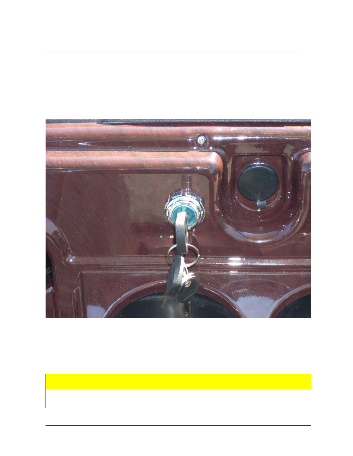
2) When charging the vehicle, be sure that the “Key Switch” is in the “OFF”
position.
3) If the key is left in the “ON“ position, it may damage the charger or the vehicle.
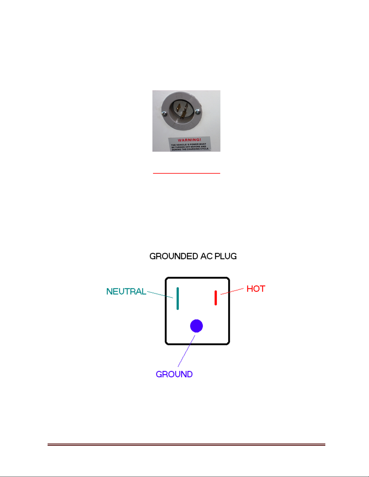
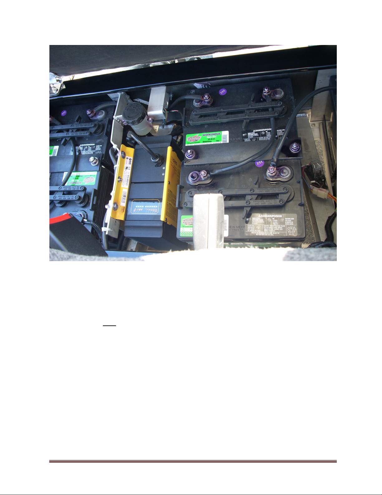
4) Your vehicle is equipped ith an on-board UL- listed charger. When charging
your vehicle, please be sure to use a proper, grounded cord to provide po er to
the charger. (see Table T, Page 6 for details)
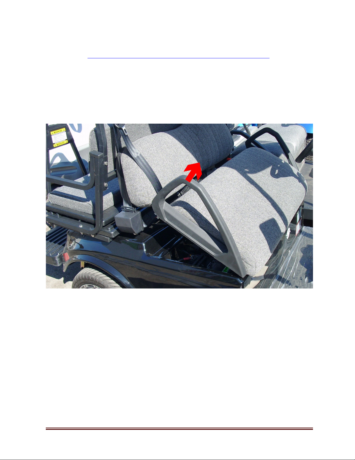
5) Please be sure to raise the hood of the vehicle to allo ventilation of the
charger so that it does not overheat.
Please refer to the separate “Owner’s Manual” for further detailed infor ation
about your vehicle.
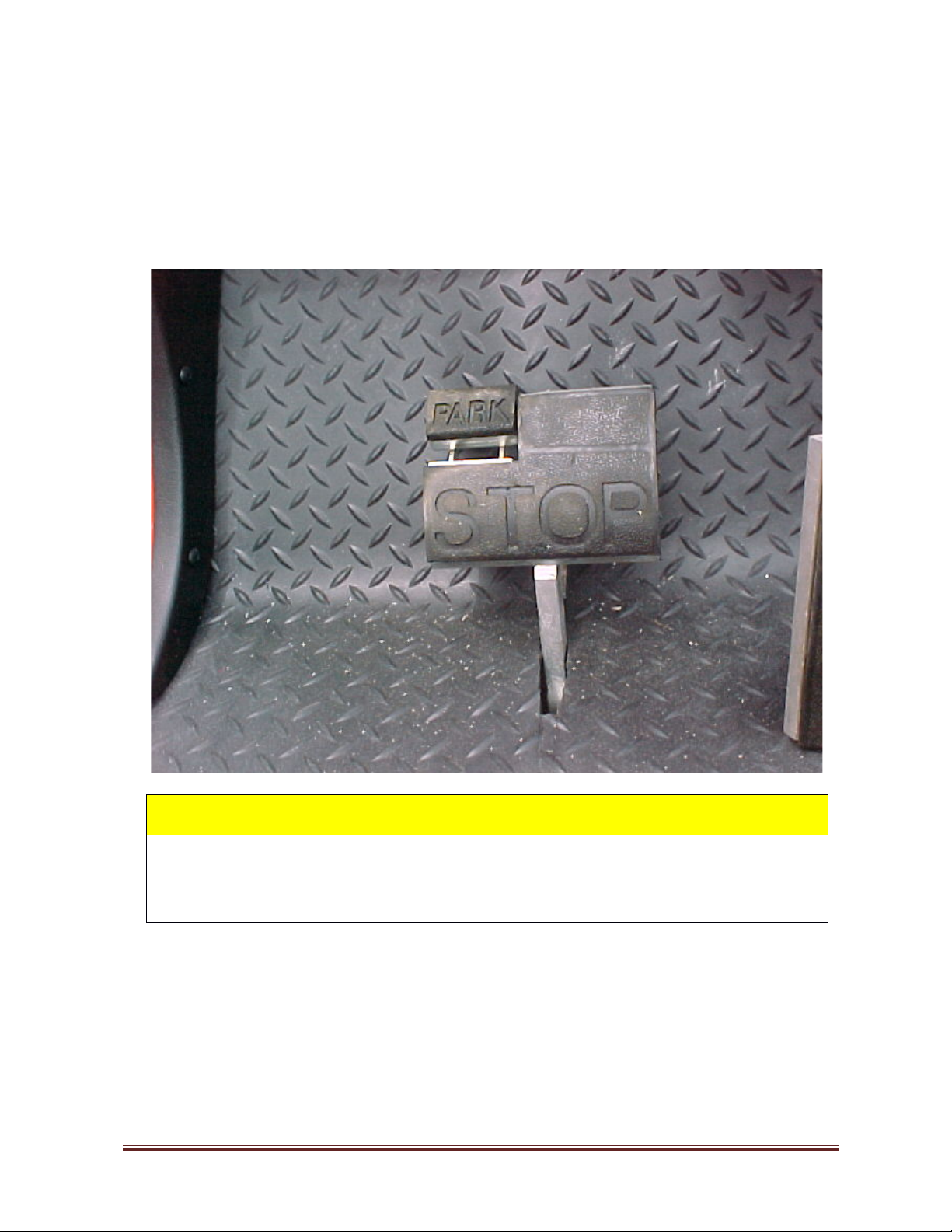
6) When stopping and leaving the vehicle:
a) Make sure vehicle has come to a complete stop.
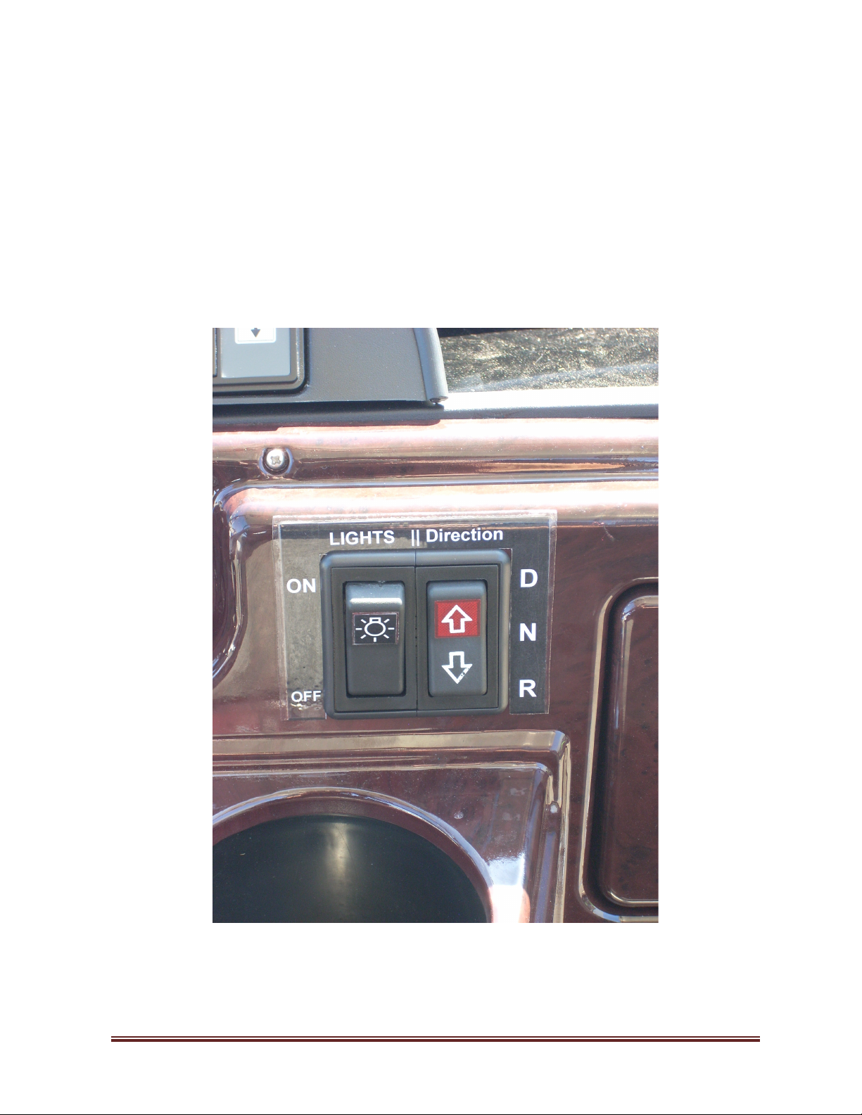
b) S itch the “Direction Control Switch” to the central “Neutral” position N.
c) Fully engage parking brake.
d) Turn the “Key Switch” counter-clock ise to “OFF” position (vertical).
e) Remove the key.
Charging Procedure Page 2

VEHICLE CHARGING
Follow the recommended “step-by-step” procedure below to re-charge the vehicle.
MAIN KEY SWITCH
Turn the ke switch located to the right of the Steering Column counter-clockwise to the
“OFF” position (vertical).
(As Shown in Picture below)
The “Key Switch” is mou ted o the dash to the right of the steeri g colum .
It has two positio s:
1. OFF position- “OFF” There is o power to vehicle. (Key is Vertical as shown above)
2. ON position- vehicle is “ON” a d ca be drive . (Key is turned clockwise 45 degrees)
WARNING!
The Vehicle Power must be tur ed “OFF” before a d duri g the Chargi g
Cycle. Failure to do so may cause Vehicle damage.
Charging Procedure Page 3

PARKING BRAKE
Full appl the parking brake b depressing the portion of the Brake Pedal (STOP) that
is labeled “PARK”.
Verify that the Brake Pedal is i locked (PARK) positio a d the vehicle is statio ary.
WARNING!
The “Park Brake” will release auto atically when either the “Accelerator
Pedal” or “Brake Pedal” is depressed. The park brake has ultiple locking
positions and should be fir ly pressed and locked to prevent the vehicle
fro rolling.
Charging Procedure Page 4

Direction Control Switch
The “Direction Control Switch” is a 3 positio “rocker” switch that is located o the vehicle
dash pa el to the right of the vehicle ce ter a d to the right of the “ ights Switch”. The switch
is labeled “Direction”.
There are three (3) disti ct positio s: D, N a d R a d so i dicated o label to the Right of the
switch.
S itch the “Direction Control Switch” to the central “Neutral” position N.
(Direction Switch shown in ”Neutral” position)
Charging Procedure Page 5

AC Cord
a.) Plug the AC Extension Cord into the vehicle charging inlet socket located at the
center of the vehicle under the Front seats.
CAUTION:
AC Exte sio Cord must be of suitable le gth a d proper AWG.
(See Table T on Page 6 for proper AWG wire size)
Plug the other end of the AC Extension Cord into 120V AC 3-conductor (Grounded)
120V AC household socket that is fused at a minimum of 15 Amp; 20 Amp circuit is
preferable if available. (or optionally see item “b” on next page)
Charging Procedure Page 6

b.) Plug the other e d of the exte sio cord i to fro t of the Kill-A-Watt Meter
c.) Plug the Kill-A-Watt Meter i to 120V AC household socket that is fused at a mi imum of
15 Amp; 20 Amp circuit is preferable if available.
d.) AVOID co ecti g a y other device or applia ce i to the same 15A/20A circuit or the
circuit may become overloaded, which will result i trippi g of the circuit breaker.
Kill-A-Watt Meter – if you use this optio al device to mo itor chargi g refer to Page 11 for
operati g i structio s.
Table T (AWG extension cable selection)
Extension Cable Length Minimum AWG rating (Wire Size)
100 Feet 10 - AWG
50 Feet 12 - AWG
25 Feet 14 - AWG
12 Feet 14 - AWG
6 Feet 16 - AWG
3 Feet 16 - AWG
Charging Procedure Page 7

48 V SYSTEM CHARGER (TRACTION Batteries)
a.) Lift the Front Bench seat b grabbing either Right or Left handlebar at the top as
shown below and indicated b .
b.) The Seat will rotate on the hinge that is installed at the Front of the seat cushion.
c.) Traction Batteries, Brake Fluid Reservoir and the On-board Charger are located
under the seat. (as shown in photo on next page)
Charging Procedure Page 8

Check the Charger LED displa
a.) verif that the charger ON telltale LED (~) on the Charger is lighted.
Co ditio YELLOW = ON
b.) verif that one of the charger charge rate telltale LEDs ( I – IIIIII ) on the
Charger is lighted
Co ditio YELLOW = ON = OK/Chargi g
Co ditio YELLOW = FLASHING = OK/Chargi g at reduced rate
Charging Procedure Page 9

Charger ON
(Start of Charge)
NOTE:
If the Traction Batter is full depleted the 48 V SYSTEM CHARGER will
remain in the Minimum Charge rate mode (Yellow LED I Lighted) for several
minutes, if the Traction Batter is not full depleted, the Charger will
automaticall switch to the Maximum Charge Rate Mode (Yellow LED IIIIII
lighted) in just few seconds.
Charger ON
(Max rate of Charge)
As chargi g progresses the Charge Algorithm reduces the charge rate either due
to state of battery charge or due to excessive i ter al charger temperature.
Charging Procedure Page 10

If the chargi g rate is reduced due to state of battery charge, o e of the Yellow
LEDs i the upper Six LED Ammeter sectio will be ON.
The Yellow LED with SIX bars (IIIIII) i dicates Maximum Rate of Charge –
Charger power i put of about 10 to 11 Amperes @ 120 V AC.
The Yellow LED with ONE bar (I) i dicates Minimum Rate of Charge – Charger
power i put of about 1 to 2 Amperes @ 120 V AC.
If the charge rate is reduced due to high i ter al charger temperature the
appropriate Ammeter LED will be Flashi g.
Whe a y of the Ammeter Yellow LEDs Flashes, the Total Chargi g Time will be
i creased!
Charger ON
(Min rate of Charge)
Whe the “80 state of Charge” is reached the Yellow LED i dicati g 80%
charge will be lighted.
Bulk charge phase is complete and the charger is now in Absorption charge phase.
Charging Procedure Page 11

Charger ON
(Min rate of Charge)
(80 state of Charge)
When Absorption charge phase is completed and the charger now enters the Finish
charge phase Green LED indicating “End of Charge” charge will be Flashing.
Whe the “100 state of Charge” is reached the Gree LED i dicati g “End of
Charge” charge will be lighted co ti uously.
Charger ON / Stand-by
(End of Charge)
(Maintenance Mode)
Whe the “End of Charge” co ditio is reached the Charger will automatically
switch to “Maintenance Mode”.
Charger will Auto-restart if 30 days elapse or if Tractio Battery Voltage drops to
below 50.4 Volts. ( Voltage less than 2.1V per battery cell )
Charging Procedure Page 12

VEHICLE CHARGING ( End of Charge )
Follow the reco ended step-by-step procedure after vehicle was re-charged.
a.) 48 V SYSTEM CHARGER (TRACTION Batteries) -
a.) verif that the charger ON telltale LED (~) on the Charger is lighted.
Co ditio YELLOW = ON
b.) verif that end of the charge telltale LED on the Charger is lighted.
Co ditio GREEN = FULLY CHARGED
b.) Kill-A-Watt Meter – if you use this optio al device to mo itor chargi g refer to Page 14
for operati g i structio s.
Record the Accumulated data: “Total Charging Time” and “Total kWh”
c.) Exte sio Cord – U plug the 120V AC exte sio power cord from vehicle
chargi g i let socket.
d.) Exte sio Cord - U plug the exte sio power cord from the household power
socket a d stove it properly.
Charging Procedure Page 13

P3 - KILL A WATT TM
Operation Manual
1. The LCD sho s all meter readings: Volts, Current, Watts, Frequency, Po er Factor,
and VA. The unit ill start to accumulate kWh and po ered duration time (hours &
minutes) after po er is applied.
2. Press Volt Key for true RMS Voltage (Volts) display.
3. Press Amp Key for true RMS output current (A ps) display.
4. The Watt/VA Key is a toggle function key. Press the Watt/VA key once to display
Watt eter, then press the Watt/VA key again to display VA eter. The LCD ill
display Watts as the active po er, here VA is the apparent Po er.
(VA = Vrms * Arms)
5. The HZ/PF is a toggle function key. Press the HZ/PF key once to display the
frequency (Hertz), then press key again to display the Power Factor. HZ is the
Frequency of output Voltage, here PF is the Po er Factor (PF = W / Vrms Arms).
6. The KWH/Hour is a toggle function key. Press the KWH/Hour key once to sho the
cumulative energy consumption since po er as applied to the unit (kWh). Then
press key to display the cumulative time since po er as applied to the unit.
7. Consumption ill be displayed in Kilo att-Hours (from 0.01 KWH to 9999 KWH).
Time ill initially be displayed as Hours:Minutes (from 00:00) and s itch to Hours (to
9999). Counters ill recycle to zero hen they reach their maximum.
8. To reset all counters to zero, remove po er from unit momentarily for about 15
seconds.
Charging Procedure Page 14

WARNING!
Do not exceed maximum ratings as detailed on label.
Button 1 = Volt
Button 2 = A p
Button 3 = Watt / VA (toggle)
Button 4 = Hz / PF (toggle)
Button 5 = kWh / TIME (toggle)
Charging Procedure Page 15

2012-01-NEV
TSPORT NEV
Manufactured by:
American Custom Golf Cars, Inc. (ACG)
15740 El Prado Rd.
Chino, CA 91710 USA
(909) 597-2885
(909) 597-7183 fax
www.acgcars.com
Copyright © 2009-2011 America Custom Golf Cars, I c.
ACG logo:
Is registered trademark of America Custom Golf Cars, I c.
.
.
Table of contents
Other ACG Golf Car manuals

ACG
ACG HUMMER H3 2014 User manual

ACG
ACG T SPORT NEV User manual

ACG
ACG Cadillac ESCALADE eGC 2014 User manual

ACG
ACG T-SPORT NEV 2014 User manual

ACG
ACG California Roadster NEV 2016 User manual

ACG
ACG 39 Roadster eGC 2012 User manual

ACG
ACG 2013 T-SPORT User manual

ACG
ACG 39Roadster eGC 2013 User manual

ACG
ACG HUMMER H3 2011 User manual

ACG
ACG 2015 Hummer H3 User manual
Popular Golf Car manuals by other brands

Club Car
Club Car 1995 Golf Car Maintenance service supplement

Massimo
Massimo T-BOSS 410 X Owner's/operator's manual

Ingersoll-Rand
Ingersoll-Rand Club Car TEMPO Operator's manual

Daymak
Daymak Boomerbuggy V user manual

CRICKET MINI GOLF CARTS
CRICKET MINI GOLF CARTS LOCUST owner's manual

Tektite
Tektite Toro Groundsmaster 4100-D manual