aci ADARAC Aluminum M Series User manual

Thank you for purchasing ADARAC™ Products. Agri-Cover, Inc. proudly manufactured
this product using superior quality materials and workmanship. With proper care, your
product will provide years of service and enjoyment.
NOTICE TO INSTALLER: Even if familiar with hardware, read instructions prior to
installation as improvements may be made without notice. Always handle components
with care. If you have questions or problems call customer service. When done, these
instructions must be given to the consumer.
NOTICE TO CONSUMER: Before using this product, read maintenance and safety
sections. Save these instructions for future reference.
FOR YOUR RECORDS
DATE PURCHASED:
WHERE PURCHASED:
SERIAL NUMBER:
(Located on side rail)
INSTALLATION INSTRUCTIONS
Questions? 866-630-8726
agricover.com

2
!WARNING
The ADARAC™ Truck Bed Rack, ADARAC™ Aluminum M-Series, ADARAC™
Aluminum Series, ADARAC™ Aluminum Pro Series and ADARACTM Aluminum Upright
Kits have a load capacity of 250 lbs. per cross bar and a maximum load capacity of
500 lbs., evenly distributed among cross bars. Always secure cargo properly. Failure to
secure cargo or hauling inappropriate cargo may result in personal injury or death. Agri-
Cover, Inc. is not responsible for any property damage, personal injury or death incurred
while using any Agri-Cover, Inc. product.
!CAUTION
These products are only intended for transporting cargo evenly distributed on cross bars.
It is the responsibility of the user to secure these materials to the rack before transporting.
Never load your rack to exceed the safe capacity of your vehicle.
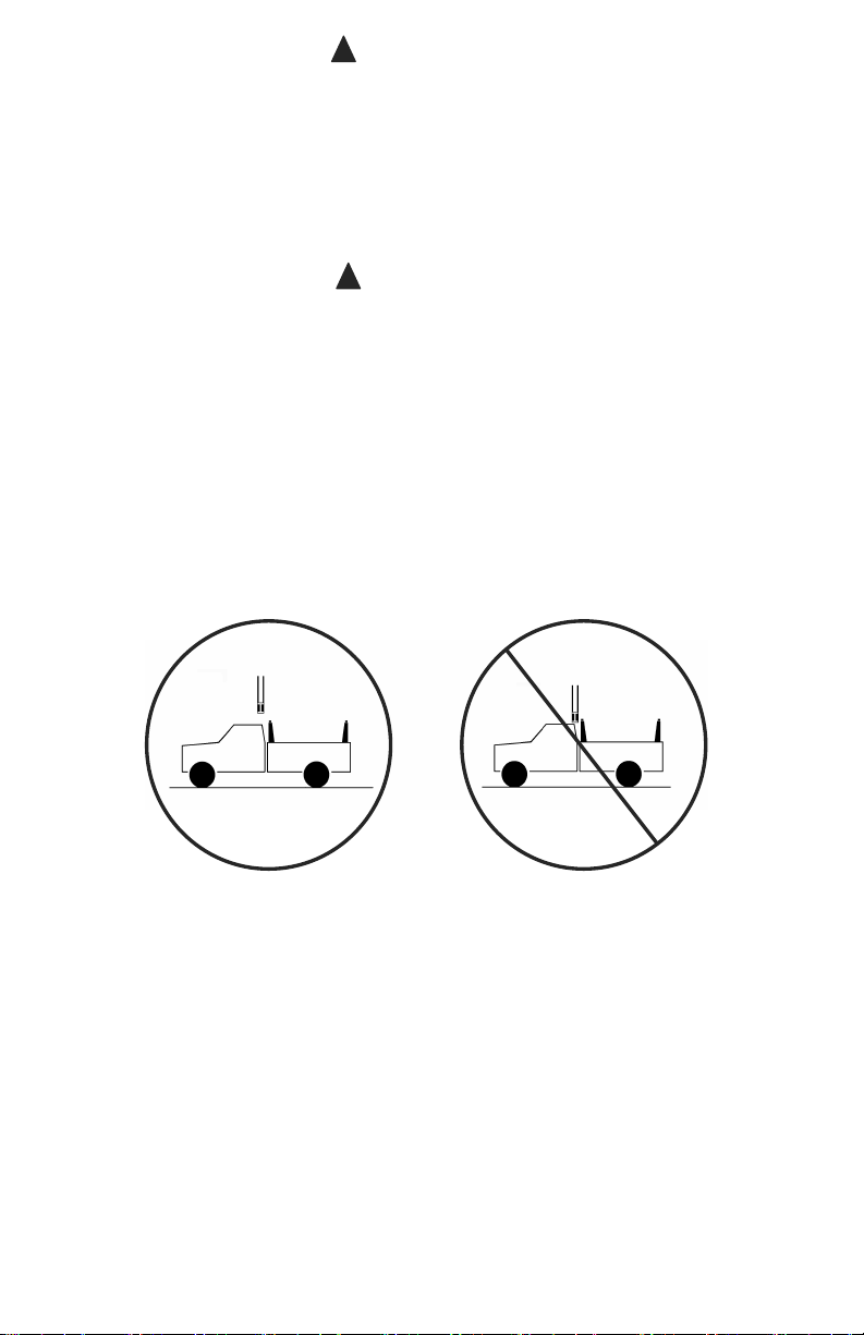
Heavy loads when carried high can dangerously alter the center of gravity of your
vehicle. Consult your vehicle’s owner’s manual for specications on load ratings and
recommendations of installation of aftermarket racks. Any modications made to this
product or use of this product for any other purpose than its intended use could create a
hazardous condition that can cause serious personal injury or property damage.
NOTE
Before entering low clearance areas, check height clearance to ensure safe entry
(empty or loaded).
NOTICE
Any modication or unintended use of these products shall immediately void all
manufacturer's warranties. Manufacturer disclaims all liability for injuries to persons or
property resulting from any modication to or unintended use of these products.
Some vehicle manufacturers require a reinforcing kit, available through the vehicle
dealership, to be installed on the truck box prior to mounting any kind of rack. Contact
your dealership to see if your vehicle requires a reinforcing kit before installation.
NOTE: Installation and use of any box rail mounted accessory may cause minor
aesthetic damage to exterior of vehicle. Agri-Cover, Inc. makes no claims or warranties
as to a particular vehicles ability to support rail mounted accessories without incurring
damage. See your vehicle manufacturer’s specications for bed rail mounted
accessories.

2 3
OVERVIEW
All ADARAC™ Truck Bed Racks and Kits support ACCESS®Roll-Up Covers.
ADARAC™ Aluminum Pro Series and Vertical Pro Upright Kits support full use of a
LOMAX™ Folding Hard Cover.
PREPARATION
Unpack components and clean truck box rails. For additional installation assistance, go
to adarac.com for install video.
RAIL COMPONENTS
• (2) Rails with hardware
• (4) Rail end caps with hardware
• Clamp plates (quantity varies)
• Alignment plates (quantity varies)
UPRIGHT COMPONENTS
• (4) Uprights with hardware
• (2) Cross bars with hardware
• (4) End caps with hardware
• (2) Stabilizing rubber ADARAC™
Aluminum models only)
TOOLS NEEDED
• Protective eyewear
• Ratchet with 9/16" socket and
extension
• Phillips screwdriver (rails only)
• Tape measure (uprights only)
• 9/16" Open end wrench (optional)
SAFETY INFORMATION
• Read and adhere to safety warnings and cautions.
• Don't exceed weight rating of rack or upright kits and always distribute weight evenly.
• Don't exceed weight rating of truck.
• Always secure objects to ADARAC™.
• Always use caution when loading or unloading cargo.
• Team load and unload heavy or cumbersome objects.
• Always drive cautiously with cargo on ADARAC™. Additional weight changes
dynamics of driving.
• Be aware of total vehicle height with ADARAC™ and cargo, ensure safe passage
under any low clearances.
• Verify ADARAC™ and accessories are mounted securely before loading cargo or
operating truck.
• Consult your vehicle’s owner’s manual for load ratings and recommendations of
installation of aftermarket racks.
• If required, use dealer reinforcing kit.

4
PARTS DIAGRAM:
ADARAC™ ALUMINUM MODELS
NOTE: Components and hardware may vary.
Alignment plate
Clamp plate
Utility rail
End cap
Upright
Rail end cap
Stabilizing rubber
Cross bar

4 5
PARTS DIAGRAM:
ADARAC™ ALUMINUM MODELS

6
PARTS DIAGRAM:
ADARAC™ TRUCK BED RACK
NOTE: Components and hardware may vary.
Alignment plate
Clamp plate
Rail
End cap
Upright
Cross bar

6 7

8
RAIL INSTALLATION
NOTE: For upright installation, see page 10.
1: PREPARING CLAMP ASSEMBLY AND RAILS
IMPORTANT: Stake pockets must be open to install this product.
ASSEMBLE THREADED CLAMP
A. Loop cord around extended threads on
clamp plate, add alignment plates equally
then tie knot at top of cord.
NOTE: Each cord should have a threaded
clamp plate and one or more alignment plates.
Tie loose ends
in a knot
Alignment
plates
(quantity
varies)
Clamp plate
Extended threads
RAILS WITH MOUNTING CHANNELS
NOTE: If your rails do not have mounting
channels, proceed to Step 2.
A. Place rail on at surface and insert (4)
channel nuts with extended threads facing
away from slotted hole.
TIP:If installing optional rail accessories,
insert additional channel nuts to support
the accessories. For more information see
accessory instructions.
Mounting channel
Channel nut Slotted hole
B. Insert rail end caps into both sides of rail.
C. Tighten rail end cap retaining screws with
Phillips screwdriver.
D. Repeat for remaining rail.
Rail end cap
Retaining
screw

8 9
2: INSTALLING RAIL
A. Align rail and long slotted holes over stake
pockets.
NOTE: Do not allow rail to pass front edge
of box.
B. Lift rail until slotted hole is accessible
from bottom. Route knot in cord under and
through slotted hole then drop clamp plate
into stake pocket and lower rail.
IMPORTANT: Ensure extended threads on
clamp plate are toward the box fl oor.
C. Move cord until clamp and alignment
plates line up with stake pocket. Pull cord
up until clamp and alignment plates are
held against stake pocket and bottom of rail.
Then turn 3/8" x 1-1/2" hex bolt into threaded
clamp until nger tight.
D. Repeat Step 2A-C for front stake pocket.
E. Slowly close tailgate to ensure it does not
hit or rub against rail. If needed, adjust rail
forward.
TIP:For easy removal of internal parts later,
undo knot in cord, make single knots at each
end and then push cord into stake pocket.
F. Remove cords and fully tighten all
bolts with a ratchet and 9/16" socket until
serrations on anges are seated tightly.
G. Repeat for rail on opposite side.
Alignment plates
(quantity varies)
Extended threads
toward box oor

10
UPRIGHT INSTALLATION
1: PREPARING UPRIGHTS
NOTE:If present, peel masking (protective
lm) off uprights. Wipe away any remaining
adhesive residue.
A. At top of upright, thread (2) 3/8" x 7/8"
hex bolts from the bottom of bolt holes into
mounting bracket. Leave mounting bracket
loose for now.
B. Repeat for each upright.
IMPORTANT:Ensure extended threads
on mounting bracket face up.
NOTE:Aluminum Pro Series and Vertical
Pro Uprights use 3/8" x 5/8" hex bolts.
Top of
upright
3/8" x 7/8"
Hex bolts
Mounting
bracket
Extended
threads
2: ASSEMBLING UPRIGHTS
IMPORTANT: Always measure upright
locations. Truck boxes may vary from
front to rear.
A. Measure and record mounting distance
between inside rails at preferred locations.
NOTE: Upright mounting locations are user
de ned and vary based on application.
Measure front
Measure rear
Measure to inside
of rack rails
Tip:If installing optional cross bar
accessories, insert channel nut(s) on
accessory into cross bar channel before
attaching uprights. For more information see
accessory instructions.
Tip: Attach uprights with mounting bracket
to cross bar while components are on a at
surface.
B. Slide mounting bracket into bottom cross
bar channel.
NOTE: Cross bar appearance may vary.
Upright
Cross bar
Mounting
bracket
Bottom cross
bar channel

10 11
2: ASSEMBLING UPRIGHTS (Continued)
C. Space bottom of uprights to match
measurement recorded earlier of distance
between rails. Center cross bar then turn bolts
snug enough to prevent cross bar slippage.
Turn bolts snug
on both sides
Equal on
both sides
Set front uprights to
front measurement
Set rear uprights to
rear measurement
Cross bar
End cap
Upright
NOTE: For black steel Truck Bed Racks, see
special end cap installation below.
D. Thread 3/8" x 3/4" hex bolt from bottom
of end cap bolt hole into channel nut. Leave
loose for now.
IMPORTANT:Ensure extended threads
on channel nut face up.
End cap
Extended
threads on
channel nut
3/8" x 3/4"
Hex bolt
E. Slide channel nut on end cap assembly
into cross bar channel. Fully tighten bolt with
a ratchet and 9/16" socket until serrations on
anges are seated tightly.
!CAUTION: Over tightening hardware
may damage components.
F. Repeat for end cap on opposite side.
G. Repeat Step 2 for remaining uprights and
cross bar.
3/8" x 3/4"
Hex bolt
End cap
BLACK STEEL TRUCK BED RACKS
A. Install end caps to both sides of cross bar.
B. Repeat Step 2 for remaining uprights and
cross bar. End cap

12
3: MOUNTING UPRIGHTS
A. Set upright assembly in the desired front
position between rails.
B. Uprights should t snug in between rails. If
needed, adjust cross bar mounts until uprights
t snug.
Upright in
between rails
Depending on rail, perform one of the
following:
RAILS WITH MOUNTING CHANNELS:
A. Align channel nuts with bolt holes in
uprights.
B. Thread 3/8" x 3/4" hex bolts into channel
nuts on both sides and nger tighten.
NOTE:Aluminum Pro Series and Vertical
Pro Uprights use 3/8" x 5/8" hex bolts.
3/8" x 3/4"
Hex bolts
Channel nuts
Upright mounting
holes
Mounting channel
C. Check for equal distance from closest
edge of box to upright. Adjust if distance to
box edge is unequal. Use a ratchet with 9/16"
socket to tighten bolts snug enough to prevent
slippage.
D. Repeat for remaining uprights.
Same distance

12 13
3. MOUNTING UPRIGHTS (Continued)
RACK RAILS WITH BOLT HOLES:
A. Align front uprights with desired rack rail
mounting holes then secure each upright
with (2) 3/8" x 1" carriage bolts and nylock
ange nuts.
B. Repeat for rear uprights.
3/8" x 1"
Carriage bolts
Front upright
Nylock ange nuts
UPRIGHT MOUNTING TIPS:
Verify if uprights were installed correctly:
Correct installation: The cross bar centers
without binding between uprights.
CORRECT
Tailgate
Incorrect installation: The cross bar centers
with binding between uprights, forcing cross
bar to bow up or down.
If required, adjust cross bar or upright mounts
until uprights and cross bar installs correctly
without bowing up or down.
INCORRECT
Tailgate

14
4. TIGHTENING HARDWARE
A. After verifying uprights and cross bars
are installed correctly, fully tighten all
bolts with a ratchet and 9/16" socket until
serrations on anges are seated tightly.
B. Periodically check the bolts at the
following locations:
Uprights: All bolts attaching cross bars to
uprights.
Rails: All bolts attaching uprights to rails.

14 15
GENERAL TROUBLESHOOTING
PROBLEM SOLUTION
Upright assembly is too wide or narrow to
t snug in between rails.
A. Loosen cross bar mounting bracket,
adjust uprights to required location,
tighten cross bar mounting bracket.
Cross bar bows up or down A. Check weight. Do not exceed weight
rating.
B. Check bolts are not loose.
C. Loosen cross bar mounts and adjust
uprights to required location.
D. Cross bar may be damaged and
require replacement.
Uprights are uneven A. Ensure base of uprights are equal
distance from closest end of box.
Tailgate has trouble closing A. Adjust rack rails forward.
NOTE:Do not allow rack rail to pass front
edge of box.
Uprights interfere with opening or closing
LOMAX™ Folding Hard Cover on
ADARAC™ Aluminum Pro Series
A. Adjust uprights evenly outward on
cross bar until LOMAX™ opens and
closes without obstruction.
INSPECTION AND MAINTENANCE
The consumer can perform most of inspection and maintenance. It may be necessary
to review instructions.
• Periodically inspect condition of all parts. Check for loose bolts and parts, tighten if
needed.
• Replace damaged parts.
NOTE: Inspection and/or maintenance should also be performed anytime a
malfunction is observed or suspected. If you need assistance inspecting and/or
servicing your ADARAC™ call Customer Service at 866-630-8726. If you want to
order a replacement part, call Customer Service. Always use original equipment
replacement parts for your ADARAC™.

MANUFACTURER’S LIMITED WARRANTY
Agri-Cover, Inc. extends the following one (1) year Limited Warranty for the ADARAC™ Truck
Bed Rack, ADARAC™ Aluminum M-Series, ADARAC™ Aluminum Series, ADARAC™
Aluminum Pro Series and ADARAC™ Rail and Upright Kits:
Agri-Cover, Inc. warrants for a period of one (1) year from the date of manufacture that
its ADARAC™ Truck Bed Rack, ADARAC™ Aluminum M-Series, ADARAC™ Aluminum
Series, ADARAC™ Aluminum Pro Series and ADARAC™ Rail and Upright Kits are free
from defects in workmanship, under normal use for the vehicle model it was intended
for. This Limited Warranty does not cover any damage due to accident, abuse, misuse,
alteration, neglect, improper installation, or ordinary wear and tear.
Agri-Cover, Inc.’s sole obligation under this Limited Warranty is limited to the repair or
replacement, at its option, of defective parts only. No labor or service allowance is given
or implied. IN NO EVENT SHALL AGRI-COVER, INC. BE LIABLE FOR INCIDENTAL,
CONSEQUENTIAL, OR SPECIAL DAMAGES. AGRI-COVER, INC. EXPRESSLY
DISCLAIMS ANY AND ALL IMPLIED WARRANTIES OF MERCHANTABILITY AND
THERE ARE NO WARRANTIES WHICH EXTEND BEYOND THE LIMITED WARRANTY
DESCRIPTION CONTAINED HEREIN.
For warranty, ll out the warranty claim form at www.agricover.com/warrantyclaim or call
our Customer Service Department at 866-630-8726 to determine if only a replacement
part is needed or if the rack needs to be returned for inspection and repair. Goods to be
returned must have a pre-authorized RA # (Return Authorization Number) - obtained by
calling the number above. Mark the number on the package and ship it freight prepaid to
address below. Agri-Cover, Inc. will pay freight to return goods to sender.
This Limited Warranty gives you speci c legal rights and you may have other rights, which
vary, from state to state.
For replacement parts, shop at adaracparts.com or call Customer Service at
866-630-8726.
032420 2000117_I
Hours: 8:00 am - 5:00 pm CST Monday through Friday, except Holidays
Agri-Cover, Inc.
Customer Service Dept
3000 Hwy 281 SE
Jamestown, ND 58401
Phone: 866-630-8726
© 2020 AGRI-COVER, INC. ALL RIGHTS RESERVED.
Product subject to change without notice. Patents: agricover.com/patents.
This manual suits for next models
4
Table of contents
Other aci Automobile Accessories manuals
Popular Automobile Accessories manuals by other brands

Bluesky
Bluesky 1001A user guide

Weather Guard
Weather Guard 96111-3-02 installation manual

Weather Guard
Weather Guard 9444-3-01 installation manual

Silvercrest
Silvercrest SBTF 10 C2 operating instructions

Maxxair
Maxxair SKYMAXX LX 97000i Installation, operation and maintenance instructions

FormFit
FormFit 20K 01 installation instructions

FormFit
FormFit HD 29R11 installation instructions

Etac
Etac Immedia AutoTurn Instructions for use

Flopro
Flopro 767 Installation instructions manual

Matt:e
Matt:e ARD-1-32-TP-M installation manual

BM PRO
BM PRO TrailSafe Series owner's manual

Pro-gard Products LLC.
Pro-gard Products LLC. GVM5419X-X installation guide