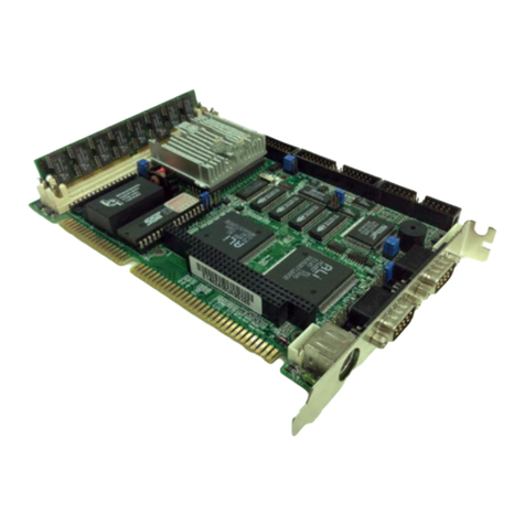
aci AFP Series Installation instructions

Automation Components, Inc.
2305 Pleasant View Road | Middleton, WI 53562
Phone: 1-888-967-5224 | Website: workaci.com
Page 1
Version: 7.0
I0000584
GENERAL INFORMATION
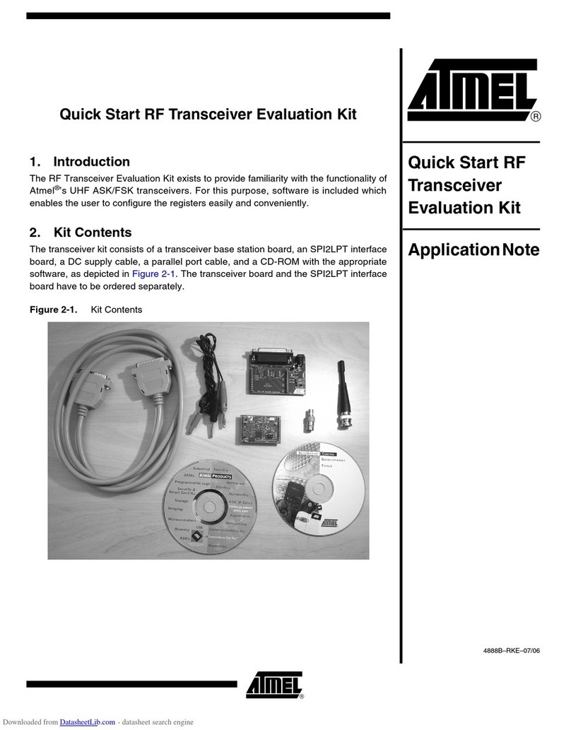
The AFP allows an analog (voltage or current)
signal to control a oating point actuator. It
converts an analog signal into two relay contact
outputs (one increase/one decrease). The isolated
oating point output can be controlled by any one
of nine analog input signal ranges (using an oset
jumper). Upon power-up, the decrease relay will
drive 100% of the chosen timing range to ensure
that the output is at its minimum position. On a
loss of power, the output relays will be open and
no signal will be generated. The actuator will
remain at the last commanded position unless it
has "spring return". The AFP output rate of change
(sixteen ranges, in eight versions) is DIP switch
selectable.
MOUNTING INFORMATION
Circuit board may be mounted in any position. If
circuit board slides out of snap track, a
non-conductive “stop”may be required. Use only
ngers to remove board from snap track. Slide
out of snap track or push against side of snap
track and lift that side of the circuit board to
remove. Do not ex board. Use no tools.
WIRING INSTRUCTIONS
PRECAUTIONS
• Remove power before wiring. Never connect
or disconnect wiring with power applied.
• When using a shielded cable, ground the
shield only at the controller end. Grounding
both ends can cause a ground loop.
• It is recommended you use an isolated
UL-listed class 2 transformer when powering
the unit with 24 VAC. Failure to wire the
devices with the correct polarity when sharing
transformers may result in damage to any
device powered by the shared transformer.
• If the 24 VDC or 24VAC power is shared with
devices that have coils such as relays,
solenoids, or other inductors, each coil must
have an MOV, DC/AC Transorb, Transient
Voltage Suppressor (ACI Part: 142583), or
diode placed across the coil or inductor. The
cathode, or banded side of the DC Transorb or
diode, connects to the positive side of the
power supply. Without these snubbers, coils
produce very large voltage spikes when
de-energizing that can cause malfunction or
destruction of electronic circuits.
• All wiring must comply with all local and
National Electric Codes.
FIGURE 1: DIMENSIONS
INTERFACE SERIES
Installation & Operation Instructions
AFP
Phone: 1-888-967-5224
Website: workaci.com
3.25”
(82.55mm)
4.00” (101.60mm)
3.25”
(82.55mm)
3.88”(98.55mm)
0.70”
(17.78mm)

FIGURE 2: WIRING
Automation Components, Inc.
2305 Pleasant View Road | Middleton, WI 53562
Phone: 1-888-967-5224 | Website: workaci.com
Page 2
Version: 7.0
I0000584
(-)
(+)
4 - 20mA
Loop Powered
Signal
(+) 24 Volt Accessory (Option)
(+) Analog Input
(-) Analog, Power and Accessory Common
(+) Power - 24 VDC/VAC @ 50/60Hz
Relay Common
N.O. (Counter-clockwise or DOWN)
N.O. (Clockwise or UP)
To Floating
Point Actuator
Optional Wiring Setup
4 - 20mA Loop Powered Signal
Controlling a Floating Point Actuator
CCW
CW
COM
Floating
Point
Actuator
24 VAC
or 24VDC
Power
Supply

FIGURE 3: JUMPER SETTINGS
Automation Components, Inc.
2305 Pleasant View Road | Middleton, WI 53562
Phone: 1-888-967-5224 | Website: workaci.com
Page 3
Version: 7.0
I0000584
SETUP
Analog input signal ranges are jumper selectable by using Jumper
J3, see Figure 3. The output of the AFP has two relays. One relay
controls UP (increase), the other DOWN (decrease) depending, of
course, on the actuator conguration. The rate of change these
outputs make on the actuator are determined by DIP switch SW1
setting. Refer to“Rate of Change” Chart and set switches according-
ly. Jumper J6 is to be in the CD mode at all times. Due to minor
dierences in the AFP timing range and product timing range, an
error may develop between the commanded position and actual
position of the actuator. There are two ways to calibrate the unit.
Version #1 - Program AFP_0101.hex
30, 60, or 90 seconds
Switch (SW1) 1 2 34
30 sec. - - Off On
60 sec. - - Off Off
90 sec. - - On Off
Version #2 - Program AFP_0201.hex
120, 150 or 180 seconds
Switch (SW1) 1 2 34
120 sec. - - Off On
150 sec. - - Off Off
180 sec. - - On Off
Drives actuator 200% of range if power is reapplied
Version #3 - Program AFP_0301.hex
14, 16.5 or 19 seconds
Switch (SW1) 1 2 34
14 sec. - - Off On
16.5 sec. - - Off Off
19 sec. - - On Off
Version #4 - Program AFP_0401.hex
30, 60, or 90 seconds
Switch (SW1) 1 2 34
30 sec. - - Off On
60 sec. - - Off Off
90 sec. - - On Off
Relay stays on at Min. & Max. voltage
Version #5 - Program AFP_0501.hex
90, 135, or 180 seconds
Switch (SW1) 1 2 34
90 sec. - - Off On
135 sec. - - Off Off
180 sec. - - On Off
Relay stays on with 5% of Max. or Min. input
voltage. No overshoot on Max. or Min. input voltage
Version #6 - Program AFP_0601.hex
18, 75, or 360 seconds
Switch (SW1) 1 2 34
18 sec. - - Off On
75 sec. - - Off Off
360 sec. - - On Off
Version #7 - Program AFP_0701.hex
30, 60, or 90 seconds
Switch (SW1) 1 2 34
30 sec. - - Off On
60 sec. - - Off Off
90 sec. - - On Off
Drives actuator 105% up if power is reapplied
Version #8- Program AFP_0801.hex
46, 240, or 600 seconds
Switch (SW1) 1 2 34
46 sec. - - Off On
240 sec. - - Off Off
600 sec. - - On Off
Input Signal Type
Moving jumper to ON adds offset
to the input or 1-5, 2-10, 3-15 or
4-20mA based on what range is
selected. OFF provides input
as selected on J3 above.
Jumper must remain
on CD setting
Manual Relay Control-Digital Outputs
Off Auto Manual
FIRST METHOD
Remove power (via control relay or switch). When power is removed
and reapplied the AFP will drive or stroke the actuator down 105%
of selected timing range (200% on Version 2, 105% up on Version 7).
Whenever the input on AFP Version 2 is within 2-5% of extreme up
or down, the relay will activate for an additional time that is 100% of
selected timing range. After the AFP has driven down (or up), it will
return to the position commanded by the analog level of the input.
The analog input can remain connected during a power reset. If the
accumulated error is greater than 5% and the analog signal at 100%,
this process may need to be repeated. Allow a 5 second or greater
delay before power is applied.

Automation Components, Inc.
2305 Pleasant View Road | Middleton, WI 53562
Phone: 1-888-967-5224 | Website: workaci.com
Page 4
Version: 7.0
I0000584
SECOND METHOD
The other way to calibrate the actuator is to drive the output to 0% and 100% of selected input range.
Depending the direction and amount of developed error, it may be necessary to repeat this process. This
calibration process should be done at a time when the large changes in the actuator position will not cause
problems with the environment it is controlling. When power is applied to terminals +24V and (-), the
“POWER” LED will light. When the AFP is not powered on terminals +24v and (-), both relays are open.
Tranzorbs are incorporated in the output circuit of the AFP.
TROUBLESHOOTING & TESTING
1.) Make sure the input and oset jumper and output timing switches 3 and 4.
2.) Apply 24 VAC/VDC to the 24 (+) and (-) terminals, conrm the power LED is on and measure
voltage to conrm proper voltage. A DC voltage can be measured from the Vout (+) terminal to the
24 (-) terminal. This voltage will vary depending on the supply voltage supplied. Voltage ranges will
be from 21 to 25 VDC. Please note supply and Vout voltages if unit is not functioning properly.
Contact technical support at ACI.
3.) Y2 will drive the actuator down 105% of selected range (200% on Version 2, 105% up on Ver 7) if
power is removed and reapplied. This is to assure the device being controlled is at 0% when
command voltage is applied. Output will return to commanded position after this calibration
process.
TESTING THE OUTPUT
Note: Output is contact closure only.
Placing J4 or J5 in the H position will close the corresponding contacts or the output. Never place both at
the same time. Conrm the resistance operation of meter and connect meter only to the corresponding
output terminal. “G” terminal is common for both. Resistance can be measured now. A “dead” or “near
dead” short should be measured when the output has been placed in the “H” position. Conrm the
appropriate LED it lit. Contact tech support if the output is not functioning.
TEST PROCEDURE (Version 1, 2, 3, 5, 6, 7 & 8)
Set the input jumpers to the required input signal settings. Set all the output switches to OFF. Place jumper
J6 CD/CE in the center position or remove (do not discard or lose jumper). With power and input only
connected, ramp input signal from 0 to 100% or in steps of 20%. Y2 will turn on from 25 – 49% of set range.
Y1 will turn on and Y2 will turn o from 50 – 73% of set range. Both relays will be on at 74% or greater. This
test conrms the unit is functional and operating correctly. Reset timing switches to desired range and J6
to the CD position. Reconnect input and output connections and retry application. Contact tech support
if application problems still exist.
TEST PROCEDURE (Version 4 ONLY)
Set the input jumpers to the required input signal settings. Set all the output switches to OFF. Place jumper
J6 CD/CE in the center position or remove (do not discard or lose jumper). With power and input only
connected, ramp input signal from 0 to 100% or in steps of 20%. Both relays will be on at 0-25%.Y1 will turn
on from 25 – 49% of set range. Y2 will turn on and Y1 will turn o from 50 – 73% of set range. Both relays
will be o at 74% or greater. This test conrms the unit is functional and operating correctly. Reset timing
switches to desired range and J6 to the CD position. Reconnect input and output connections and retry
application. Contact tech support if application problems still exist.
INPUT SIGNAL JUMPERS
Refer to the input signal range and oset jumper settings shown in the diagram on page 1.
Voltage Input
Connect the “+” or positive wire to the “UP/A+” terminal. Connect the common to the “24V-“ terminal.
Apply a voltage from control source. Measure the voltage at the input terminals. If the commanded
voltage is not present, remove the“+”or positive wire and measure from + wire to the“24V-“ terminal. If no
voltage is measured, check wiring from controller. If voltage disappears or is reduced when connected to
the AFP. Conrm input jumper is set to voltage mode and remove input wires. Remove power from unit
and measure the resistance from “Vout+” to “24V-“ terminals. Resistance in the voltage modes will be
around 10K Ohms and greater. If input is shorted contact tech support at ACI. If not shorted remove the
controller input common and connect power only to AFP. NOTE: Place meter in voltage mode and
measure VAC and VDC from analog input common wire to power supply common. If any voltage is
measured in DC or AC, a ground loop most likely exists. Use a separate 24V transformer for the AFP and let
common oat.
Current Input
Conrm the input jumper is in the 20mA mode. Measured input resistance is around 250 Ohms. Connect
“+” or positive wire to “UP/A+”and input “-“ or common to“24V-“. Apply mA signal. Place meter in voltage
and measure voltage across“UP/A+” and “24V-“. 4mA is equal to 1 volt and 20mA is equal to 5 volts. Use
Ohms Law to nd voltage from current. Current x 250 Ohms = Volts.
Example: 12mA (or 0.012) x 250 Ohms = 3 Volts. If no voltage is present, check wiring for open. Current
cannot exist without voltage present unless the input is dead shorted. If problem still persist see the“Note”
in voltage section.

Automation Components, Inc.
2305 Pleasant View Road | Middleton, WI 53562
Phone: 1-888-967-5224 | Website: workaci.com
Page 5
Version: 7.0
I0000584
SECOND METHOD
The other way to calibrate the actuator is to drive the output to 0% and 100% of selected input range.
Depending the direction and amount of developed error, it may be necessary to repeat this process. This
calibration process should be done at a time when the large changes in the actuator position will not cause
problems with the environment it is controlling. When power is applied to terminals +24V and (-), the
“POWER” LED will light. When the AFP is not powered on terminals +24v and (-), both relays are open.
Tranzorbs are incorporated in the output circuit of the AFP.
TROUBLESHOOTING & TESTING
1.) Make sure the input and oset jumper and output timing switches 3 and 4.
2.) Apply 24 VAC/VDC to the 24 (+) and (-) terminals, conrm the power LED is on and measure
voltage to conrm proper voltage. A DC voltage can be measured from the Vout (+) terminal to the
24 (-) terminal. This voltage will vary depending on the supply voltage supplied. Voltage ranges will
be from 21 to 25 VDC. Please note supply and Vout voltages if unit is not functioning properly.
Contact technical support at ACI.
3.) Y2 will drive the actuator down 105% of selected range (200% on Version 2, 105% up on Ver 7) if
power is removed and reapplied. This is to assure the device being controlled is at 0% when
command voltage is applied. Output will return to commanded position after this calibration
process.
TESTING THE OUTPUT
Note: Output is contact closure only.
Placing J4 or J5 in the H position will close the corresponding contacts or the output. Never place both at
the same time. Conrm the resistance operation of meter and connect meter only to the corresponding
output terminal. “G” terminal is common for both. Resistance can be measured now. A “dead” or “near
dead” short should be measured when the output has been placed in the “H” position. Conrm the
appropriate LED it lit. Contact tech support if the output is not functioning.
TEST PROCEDURE (Version 1, 2, 3, 5, 6, 7 & 8)
Set the input jumpers to the required input signal settings. Set all the output switches to OFF. Place jumper
J6 CD/CE in the center position or remove (do not discard or lose jumper). With power and input only
connected, ramp input signal from 0 to 100% or in steps of 20%. Y2 will turn on from 25 – 49% of set range.
Y1 will turn on and Y2 will turn o from 50 – 73% of set range. Both relays will be on at 74% or greater. This
test conrms the unit is functional and operating correctly. Reset timing switches to desired range and J6
to the CD position. Reconnect input and output connections and retry application. Contact tech support
if application problems still exist.
TEST PROCEDURE (Version 4 ONLY)
Set the input jumpers to the required input signal settings. Set all the output switches to OFF. Place jumper
J6 CD/CE in the center position or remove (do not discard or lose jumper). With power and input only
connected, ramp input signal from 0 to 100% or in steps of 20%. Both relays will be on at 0-25%.Y1 will turn
on from 25 – 49% of set range. Y2 will turn on and Y1 will turn o from 50 – 73% of set range. Both relays
will be o at 74% or greater. This test conrms the unit is functional and operating correctly. Reset timing
switches to desired range and J6 to the CD position. Reconnect input and output connections and retry
application. Contact tech support if application problems still exist.
INPUT SIGNAL JUMPERS
Refer to the input signal range and oset jumper settings shown in the diagram on page 1.
Voltage Input
Connect the “+” or positive wire to the “UP/A+” terminal. Connect the common to the “24V-“ terminal.
Apply a voltage from control source. Measure the voltage at the input terminals. If the commanded
voltage is not present, remove the“+”or positive wire and measure from + wire to the“24V-“ terminal. If no
voltage is measured, check wiring from controller. If voltage disappears or is reduced when connected to
the AFP. Conrm input jumper is set to voltage mode and remove input wires. Remove power from unit
and measure the resistance from “Vout+” to “24V-“ terminals. Resistance in the voltage modes will be
around 10K Ohms and greater. If input is shorted contact tech support at ACI. If not shorted remove the
controller input common and connect power only to AFP. NOTE: Place meter in voltage mode and
measure VAC and VDC from analog input common wire to power supply common. If any voltage is
measured in DC or AC, a ground loop most likely exists. Use a separate 24V transformer for the AFP and let
common oat.
Current Input
Conrm the input jumper is in the 20mA mode. Measured input resistance is around 250 Ohms. Connect
“+” or positive wire to “UP/A+”and input “-“ or common to“24V-“. Apply mA signal. Place meter in voltage
and measure voltage across“UP/A+” and “24V-“. 4mA is equal to 1 volt and 20mA is equal to 5 volts. Use
Ohms Law to nd voltage from current. Current x 250 Ohms = Volts.
Example: 12mA (or 0.012) x 250 Ohms = 3 Volts. If no voltage is present, check wiring for open. Current
cannot exist without voltage present unless the input is dead shorted. If problem still persist see the“Note”
in voltage section.

WARRANTY
The ACI AFP Series is covered by ACI’s Two (2)Year Limited Warranty, which is located in the front of ACI’S SENSORS
& TRANSMITTERS CATALOG or can be found on ACI’s website: www.workaci.com.
PRODUCT SPECIFICATIONS
24 VAC or 24 VDC, (+/- 10%), 50/60 Hz
105 mA maximum without 24 VDC auxiliary output
190 mA maximum with 24 VDC auxiliary output
0-5 VDC, 0-10 VDC, 0-15 VDC
0-20 mA
1-5 VDC, 2-10 VDC, 3-15 VDC
4-20 mA
Voltage @ 10,000 Nominal / Current @ 250 nominal
Two relay contact outputs (Increase / Decrease)
Dry Contact, Form C, 2A maximum @ 24 VDC
100,000 operations minimum
1,000,000 operation
90° Pluggable Screw Terminal Blocks
16 (1.31 mm) to 26 AWG (0.129 mm)
0.5 Nm (Minimum); 0.6 Nm (Maximum)
35 to 120°F (1.7 to 48.9°C)
10 to 95% non-condensing
-20 to 150°F (-28.9 to 65.5°C)
Polyvinyl Chloride (PVC)
SENSOR NON-SPECIFIC INFORMATION
Supply Voltage:
Supply Current:
Input Voltage Signal Range:
Input Current Signal Range:
Analog Voltage Signal Input Range with Oset
Jumper:
Analog Current Signal Input Range with Oset
Jumper:
Input Impedances (Nominal):
Output (Floating Point):
Relay Contact Rating:
Relay Electrical Life:
Relay Mechanical Life:
Connections:
Wire Size:
Terminal Block Torque Rating:
Operating Temperature Range:
Operating Humidity Range:
Storage Temperature:
Snaptrack Material:
Automation Components, Inc.
2305 Pleasant View Road | Middleton, WI 53562
Phone: 1-888-967-5224 | Website: workaci.com
Page 6
Version: 7.0
I0000584

NOTES
Page 7
Automation Components, Inc.
2305 Pleasant View Road | Middleton, WI 53562
Phone: 1-888-967-5224 | Website: workaci.com
Version: 7.0
I0000584

Page 8
Automation Components, Inc.
2305 Pleasant View Road
Middleton, WI 53562
Phone: 1-888-967-5224
Website: workaci.com
Automation Components, Inc.
2305 Pleasant View Road | Middleton, WI 53562
Phone: 1-888-967-5224 | Website: workaci.com
Version: 7.0
I0000584
Table of contents
