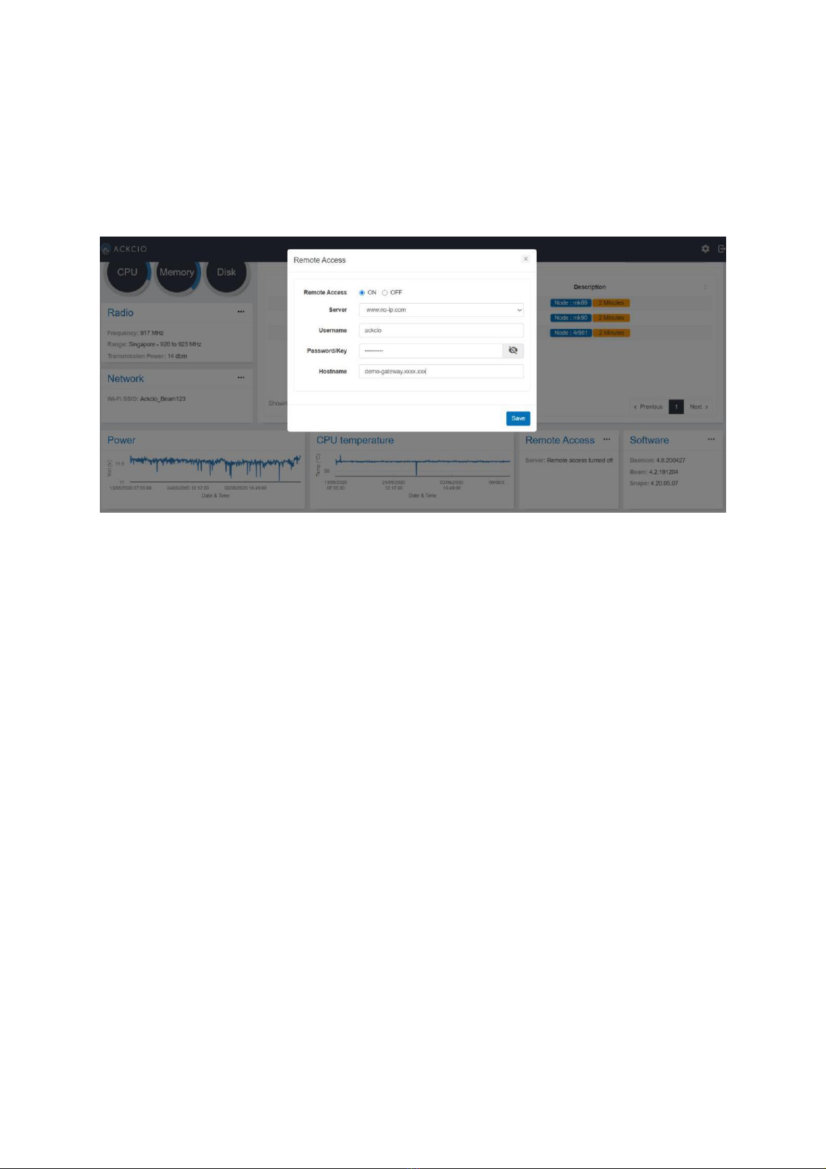
Ackcio BEAM-GW User instructions

Setting up Gateway (BEAM-GW)
This page explains the process of setting up the ACKCIO BEAM gateway device.
Installation
The gateway can be directly affixed to a flat surface using M4 screws. However, for more
sophisticated mounting scenarios, we recommend using the gateway bracket. The gateway
bracket can be used to easily mount the gateway on flat surfaces, on pipes using U-bolts, or in
other complicated settings. (One of our clients hung it using cable ties as well!)
If you are using the bracket, first fix the gateway device to the bracket using M4 screws and
nuts as shown below.
Four screws/nuts to attach the gateway to the bracket

Fix the gateway antenna and the cellular antenna to the bracket as shown below. Note that
the Gateway has two identical ports at the bottom for GPS and Cellular (GSM) antennas.
Therefore, please connect the cellular antenna to the correct port which is the GSM port.
Gateway antenna & Cellular (GSM) antenna positioning - left and right respectively

Setting up the Gateway
Gateway Settings
1. Connect a 12V DC power supply to the gateway. Ensure the polarities are affixed
correctly while the power supply is connected. The power supply can be a 12V DC
power adapter or a 12V solar panel power setup.
2. Switch on the gateway by putting the power switch to ON position.
3. Once the gateway turns on, you will see RF LED (Radio Signal) stays steady. RPI
LED will be on for about 1~2 minutes later. Do not switch off gateway while RPI
LED is solid. RPI LED will be in blinking status for about 4 minutes afterwards.
4. Once the Gateway is booted up, connect the Gateway to your laptop using a micro-
USB to LAN adaptor.
Open any browser on you PC and visit http://beam.local On the below shown screen enter
the
Username: admin
Password: adminadmin (or) admin123
Click the (Gear Icon) settings button for Gateway setting configuration.

Date
Select the time zone with respect to your country and click on “Sync" icon to sync with
computer date and time. Click Save button afterwards.
Radio
Select the country and set the “Frequency” accordingly. Afterwards set the
transmission power. Refer to the following link to get your country frequency.
https://www.thethingsnetwork.org/docs/lorawan/frequencies-by-country.html

Internet
Select either LAN or Cellular.
If Cellular is selected , choose your respective country and Service provider from the search
bar. The APN, Username & Password based on the configuration will be automatically set.
Once configuration is done, you can click on little world icon to test signal strength. You may
also tick the check box on "Enable Internet Always" if you want to enable Internet
permanently.
Cellular option for Internet
Upload Mode
Out of the three upload modes, API, FTP, ACKCIO Cloud one could select either one or
many modes to upload the data.
Upload data to an API

Enter the relevant link to which the data needs to be pushed as shown in Diagram below (1)
Upload data to a FTP server/ SFTP server
Enter the respective URL, Port, Username and password if any, and the folder to which the
data needs to be pushed as shown in the diagram below. (2)
Select ACKCIO CLOUD mode if you are setting up project at Ackcio Cloud by entering the
Ackcio Key.

Activity Grid
The activity grid will depict the key functionalities and changes that are conducted in the
gateway where one could see information with related to the changes that are made.
Using the red circled export icon in the below shown diagram one could can export the
gateway logs.

Remote Access
If the gateway needs to be accessed remotely using a dynamic DNS, it could be done by
providing the details requested, as shown below. Once they are provided the gateway could
be remotely accessed via the dynamic DNS. Also, during this procedure, it is necessary to
make sure that the gateway has the internet connection.
The Remote access configuration steps are explained below.
1. Set up a free host name and an account using one of five given dynamic dns
providers, using the web browser.
2. Once the hostname and the account information are received, go to the remote access
tile and access the model. and then type in the information regarding the hostname,
account username, and password.
3. Upon save, the ddclient file in the back-end will be configured automatically based on
what the user saves in that model and ddclient will set up the remote access.
4. The user will now be able to type in their custom hostname in the search bar and
access the gateway via said hostname instead of ip.

Software
You can find current firmware & software version in this section. by uploading the software
package provided by Ackcio one could update Gateway software when necessary. The steps
of the installation process will be shown accordingly.
That brings the end to the Gateway Settings.
Setting up with ACKCIO cloud
To kick start log in to Ackcio Cloud with your registered account.
Connect your PC to internet LAN. Click on the following link to login Ackcio Cloud
online portal with your registered account. https://live.ackcio.com
1. Procedure for adding Nodes (i) Initially add all Nodes before creating Project.

(ii) Expand the Devices list at the side menu by clicking the arrow mark. Then, Click on +
button. Device ID (Mac ID): the first 4 digits found on the sticker of the device Device
Name: Name the node as per your preference.(Ex: Your device location or sensor). No of
Channels: Select either 1,4 or 8 based on the device channels (ports). 0 is for Relay Node.
Device Type: Select Node type based on your Node. After filling up the device information,
click “Save” button.

(iii) You will see the prompt and added device information under “Device list” section.
(iv) Repeat above steps to add additional Nodes.
2. Procedure to create a new Project.
Click on “Setup” at side menu.
3. Input the requested information as per instructed below
•Name, Client, Frequency, Start Date and Location (click on pencil icon to input
the location).
•Project Controller field: mandatory.
•Gateway field: Select your respective Gateway ID(s) by clicking on text box.
•Device field: Click in text box, you will see the Node(s) which you have
already added previously. Please select accordingly. (Multiple selection)
•Sensor field: Select the respective sensor types. (Multiple selection)

Click Next.
4. You can set the desired “Sampling Rate” at this page for all the nodes. Click Next.
5. For the Alert, please enable at least one channel (either email or message)
6. Click "Setup" to complete the project creation.

7. Click on Dashboard at the side menu, you can now see newly created project. If you want
to edit the project, click on pencil button.

9. Once "Step.8" is done, please refer to Node Manual (Analogue or Vibrating Wire)
to commission the nodes.
10. After you have commissioned all the nodes, go to "Online" dashboard, click on your
project, you will now be able to see your Nodes under “Device Summary” Section.
Setting up with Third Party Services
Open your favourite browser, and visit http://192.168.0.10 . Thereby enter the
credentials. Username: admin
Password: adminadmin

Creating a Project
1. Click “+” icon next to the Projects to create new project. 2. Refresh (or) Click on "Sync
Projects" icon if you need to refresh the project or sync with a cloud project (if any). 3.
Import/Export Project Configuration if you have any previous saved project configuration
file. Please refer to this link for more information.
Input Name, Client, Start Date and Location with respect to the project that is about to be
created. (click on pencil icon to input the location).
Creating a Node
To add Nodes, click on the "+" icon next to "Nodes" section. Input credentials and save.
Node Type: Select the type of your node accordingly.
Node ID: Enter the unique ID provided in the sticker, on top of the Node.
Node Name: Name it according to your device location or sensor as per your preference.
**Repeat above steps to add additional Nodes.

You can now see the Node(s) that you have just added in the "Node List" section. On Node
text field, please select your Nodes. (You can select multiple Nodes.)
Click on the "Next" button afterwards. You will be navigated to the sensor Nodes and
sensors page.

On this screen, you will see all the added Nodes to the project on the left pane.
1. Click on arrow icon to expand selected Node information.
2. You can set a preferred “Sampling Rate (in mins)” at this page for your node.
3. Input the corresponding Sensor Code, Type and Mode.
4. You can set an equation by clicking this icon.
5. You can enable the wireless mesh, if necessary.
6. If you wish to add virtual channel, click +. Click the “Setup” button to complete the
Project Creation.
Upon successful project creation, the system will take you to the "Main" screen and you will
see newly created project. If you want to edit the project, you can do so by clicking pencil
icon.
Next step, please refer to respective Node Manuals to commission the nodes.

After you have commissioned all the nodes, log in and click on your project, you will now be
able to see your Nodes under “Node Summary” Section and sensor details under "Sensor
Summary".
Normal Operating Status of the Gateway
1. You should see (RPI, NET, RF LEDs) of the gateway should remain off most of the
time.
2. WF LED will be solid all the time unless you turn it off. (You can turn off/on WF by
pressing and holding FUNC button more than 5 seconds)
3. The RPI & RF LEDs will blink every 5 seconds.
4. The NET LED will blink if the Internet mode has been set to CELLULAR and when
there is Internet activity (e.g., real-time data uploading to a server via FTP or API).
Afterwards, the LED will turn off until next internet activity.
Turning off the Gateway
Turning off using the device
1. Press and hold the FUNC button for more than 10 seconds. You will see that the RPI,
NET, WF LEDs will be turned off.
2. RF LED may continue to blink every 5s which is normal.
3. Put the power switch to off position. RF LED will be turned off at this stage too.
Turning off / Reset using the dashboard
The gateway could be reset/brought to the initial status by clicking the "Restore" button on
gateway activity module. Yet it should be done attentively as all the data and
configurations may loose and it may need a Re - configuration.

Also its necessary to note that upon the System restart button click, the gateway would
restart and upon the shutdown button the gateway device would shutdown.
FCC Caution:
Any Changes or modifications not expressly approved by the party responsible for
compliance could void the user's authority to operate the equipment.
This device complies with part 15 of the FCC Rules. Operation is subject to the following
two conditions: (1) This device may not cause harmful interference, and (2) this device must
accept any interference received, including interference that may cause undesired operation.
FCC RF Radiation Exposure Statement:
1. This Transmitter must not be co-located or operating in conjunction
with any other antenna or transmitter.
2. This equipment complies with RF radiation exposure limits set forth for
an uncontrolled environment.
3.This equipment should be installed and operated with minimum distance 20cm between
the radiator& your body.
Table of contents