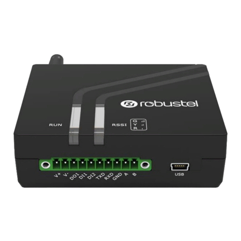
Robustel R3010 User manual

Robustel R3010 User Guide
RT_UG_R3010_v.1.0.2 31 Jul., 2018 0
Confidential
R3010
Industrial Cellular IoT
Gateway
2xEth + 1xVoice + 1xRS-232 + 1xRS-
485 +1xCAN + 1xConsole + 1xUSB
User Guide
Guangzhou Robustel LTD
www.robustel.com

Robustel R3010 User Guide
RT_UG_R3010_v.1.0.2 8 Aug., 2018 1
Confidential
About This Document
This document provides hardware and software information of the Robustel R3010 Gateway, including introduction,
installation, configuration and operation.
Copyright©2018 Guangzhou Robustel LTD
All rights reserved.
Trademarks and Permissions
is trademark of Guangzhou Robustel LTD. All other trademarks and trade names mentioned in
this document are the property of their respective owners.
Disclaimer
No part of this document may be reproduced in any form without the written permission of the copyright owner.
The contents of this document are subject to change without notice due to continued progress in methodology,
design and manufacturing. Robustel shall have no liability for any error or damage of any kind resulting from the use
of this document.
Technical Support
Tel: +86-20-29019902
Fax: +86-20-82321505
Email: support@robustel.com
Web: www.robustel.com

Robustel R3010 User Guide
RT_UG_R3010_v.1.0.2 8 Aug., 2018 2
Confidential
Important Notice
Due to the nature of wireless communications, transmission and reception of data can never be guaranteed. Data
may be delayed, corrupted (i.e., have errors) or be totally lost. Although significant delays or losses of data are rare
when wireless devices such as the gateway is used in a normal manner with a well-constructed network, the
gateway should not be used in situations where failure to transmit or receive data could result in damage of any kind
to the user or any other party, including but not limited to personal injury, death, or loss of property. Robustel
accepts no responsibility for damages of any kind resulting from delays or errors in data transmitted or received
using the gateway, or for failure of the gateway to transmit or receive such data.
Safety Precautions
General
The gateway generates radio frequency (RF) power. When using the gateway, care must be taken on safety
issues related to RF interference as well as regulations of RF equipment.
Do not use your gateway in aircraft, hospitals, petrol stations or in places where using cellular products is
prohibited.
Be sure that the gateway will not be interfering with nearby equipment. For example: pacemakers or medical
equipment. The antenna of the gateway should be away from computers, office equipment, home appliance,
etc.
An external antenna must be connected to the gateway for proper operation. Only uses approved antenna with
the gateway. Please contact authorized distributor on finding an approved antenna.
Always keep the antenna with minimum safety distance of 20 cm or more from human body. Do not put the
antenna inside metallic box, containers, etc.
RF exposure statements
1. For mobile devices without co-location (the transmitting antenna is installed or located more than 20cm
away from the body of user and nearby person)
FCC RF Radiation Exposure Statement
1. This Transmitter must not be co-located or operating in conjunction with any other antenna or transmitter.
2. This equipment complies with FCC RF radiation exposure limits set forth for an uncontrolled environment.
This equipment should be installed and operated with a minimum distance of 20 centimeters between the
radiator and human body.
Note: Some airlines may permit the use of cellular phones while the aircraft is on the ground and the door is open.
Gateway may be used at this time.
Using the Gateway in Vehicle
Check for any regulation or law authorizing the use of cellular devices in vehicle in your country before installing
the gateway.
The driver or operator of any vehicle should not operate the gateway while driving.
Install the gateway by qualified personnel. Consult your vehicle distributor for any possible interference of
electronic parts by the gateway.
The gateway should be connected to the vehicle’s supply system by using a fuse-protected terminal in the
vehicle’s fuse box.
Be careful when the gateway is powered by the vehicle’s main battery. The battery may be drained after
extended period.

Robustel R3010 User Guide
RT_UG_R3010_v.1.0.2 8 Aug., 2018 3
Confidential
Protecting Your Gateway
To ensure error-free usage, please install and operate your gateway with care. Do remember the following:
Do not expose the gateway to extreme conditions such as high humidity / rain, high temperature, direct sunlight,
caustic / harsh chemicals, dust, or water.
Do not try to disassemble or modify the gateway. There is no user serviceable part inside and the warranty
would be void.
Do not drop, hit or shake the gateway. Do not use the gateway under extreme vibrating conditions.
Do not pull the antenna or power supply cable. Attach/detach by holding the connector.
Connect the gateway only according to the instruction manual. Failure to do it will void the warranty.
In case of problem, please contact authorized distributor.

Robustel R3010 User Guide
RT_UG_R3010_v.1.0.2 31 Jul., 2018 4
Confidential
Federal Communication Commission Interference Statement
This device complies with Part 15 of the FCC Rules. Operation is subject to the following two conditions: (1) This
device may not cause harmful interference, and (2) this device must accept any interference received, including
interference that may cause undesired operation.
This equipment has been tested and found to comply with the limits for a Class B digital device, pursuant to Part 15
of the FCC Rules. These limits are designed to provide reasonable protection against harmful interference in a
residential installation. This equipment generates, uses and can radiate radio frequency energy and, if not installed
and used in accordance with the instructions, may cause harmful interference to radio communications. However,
there is no guarantee that interference will not occur in a particular installation. If this equipment does cause
harmful interference to radio or television reception, which can be determined by turning the equipment off and on,
the user is encouraged to try to correct the interference by one of the following measures:
Reorient or relocate the receiving antenna.
Increase the separation between the equipment and receiver.
Connect the equipment into an outlet on a circuit different from that to which the receiver is connected.
Consult the dealer or an experienced radio/TV technician for help.
FCC Caution:
Any changes or modifications not expressly approved by the party responsible for compliance could void the
user's authority to operate this equipment.
This transmitter must not be co-located or operating in conjunction with any other antenna or transmitter.

Robustel R3010 User Guide
RT_UG_R3010_v.1.0.2 31 Jul., 2018 5
Confidential
Industry Canada statement
This device complies with Industry Canada license-exempt RSS standard(s). Operation is subject to
the
following two conditions:
1) this device may not cause interference, and
2) this device must accept any interference, including interference that may cause
undesired operation of the device.
Le présent appareil est conforme aux CNR d'Industrie Canada applicables aux appareils radio
exempts de licence. L'exploitation est autorisée aux deux conditions suivantes:
1) l'appareil ne doit pas produire de brouillage, et
2) l'utilisateur de l'appareil doit accepter tout brouillage radioélectrique subi, même si le
brouillage
est susceptible d'en compromettre le fonctionnement.
This device and its antenna(s) must not be co-located or operating in conjunction with any
other
antenna or transmitter, except tested built-in radios.
Cet appareil et son antenne ne doivent pas être situés ou fonctionner en conjonction avec une
autre
antenne ou un autre émetteur, exception faites des radios intégrées qui ont été testées.
The County Code Selection feature is disabled for products marketed in the US/Canada.
La fonction de sélection de l'indicatif du pays est désactivée pour les produits commercialisés
aux États-Unis et au Canada.
Radiation Exposure Statement:
This equipment complies with IC radiation exposure limits set forth for an uncontrolled environment.
This equipment should be installed and operated with minimum distance 20cm between the radiator &
your body.
Déclaration d'exposition auxradiations:
Cet équipement est conforme aux limites d'exposition aux rayonnements IC établies pourun
environnement non contrôlé. Cet équipement doit être installé et utilisé avec un minimum de 20 cm de
distance entre la source de rayonnement et votre corps.

Robustel R3010 User Guide
RT_UG_R3010_v.1.0.2 31 Jul., 2018 6
Confidential
Regulatory and Type Approval Information
Table 1: Directives
2011/65/EC Directive 2011/65/EU of the European Parliament and of the Council of 8 June 2011
on the restriction of the use of certain hazardous substances in electrical and
electronic equipment (RoHS)
2012/19/EU Directive 2012/19/EU the European Parliament and of the Council
of 4 July 2012 on waste electrical and electronic equipment (WEEE)
Table 2: Standards of the Ministry of Information Industry of the People’s Republic of China
SJ/T
11363-2006
“Requirements for
Concentration Limits for Certain Hazardous Substances in Electronic
Information Products” (2006-06).
SJ/T
11364-2006
“Marking for Control of Pollution Caused by Electronic Information Products”
(2006-06).
According to the “Chinese Administration on the Control of Pollution caused
by Electronic Information Products” (ACPEIP) the EPUP, i.e., Environmental
Protection Use Period, of this product is 20 years as per the symbol shown here, unless otherwise
marked. The EPUP is valid only as long as the product is operated within the operating limits
described in the Hardware Interface Description.
Please see Table 3 for an overview of toxic or hazardous substances or elements that might be
contained in product parts in concentrations above the limits defined by SJ/T 11363-2006.
Table 3: Toxic or Hazardous Substances or Elements with Defined Concentration Limits
Name of the Part
Hazardous Substances
(Pb)
(Hg)
(Cd)
(Cr (VI) )
(PBB)
(PBDE)
Metal parts o o o o o o
Circuit modules
x
o
o
o
o
o
Cables and cable assemblies
o
o
o
o
o
o
Plastic and polymeric parts o o o o o o
o:
Indicates that this toxic or hazardous substance contained in all of the homogeneous materials for this part is
below the limit requirement in SJ/T11363-2006.
x:
Indicates that this toxic or hazardous substance contained in at least one of the homogeneous materials for this
part might exceed the limit requirement in SJ/T11363-2006.

Robustel R3010 User Guide
RT_UG_R3010_v.1.0.2 8 Aug., 2018 7
Confidential
Document History
Updates between document versions are cumulative. Therefore, the latest document version contains all updates
made to previous versions.
Date Firmware Version Doc Version Change Description
9 July, 2018 1.0.0 v.1.0.0 Initial release
24 July, 2018
1.0.0
v.1.0.1
Changed the input power to 9-26 V DC
Added some description of accessories
Revised the description of CAN
Changed the terminal block to connector
31 July, 2018 1.0.0 v.1.0.2 Added FCC and IC statements
Revised the description of LED indicators
Add CE certificate information

Robustel R3010 User Guide
RT_UG_R3010_v.1.0.2 8 Aug., 2018 8
Confidential
Contents
Chapter 1 Product Concept ........................................................................................................................... 10
1.1 Key Features............................................................................................................................................. 10
1.2 Package Contents ..................................................................................................................................... 11
1.3Specifications ...........................................................................................................................................13
1.4 Dimensions...............................................................................................................................................15
1.5 Ordering Information ...............................................................................................................................15
Chapter 2 Hardware Installation.................................................................................................................... 16
2.1 LED Indicators...........................................................................................................................................16
2.2 PIN Assignment ........................................................................................................................................18
2.3 USB Interface............................................................................................................................................ 19
2.4 Ethernet Ports ..........................................................................................................................................19
2.5 Insert or Remove SIM Card ......................................................................................................................20
2.6 Attach External Antenna (SMA Type) .......................................................................................................21
2.7 Mount the Gateway .................................................................................................................................22
2.8 Ground the Gateway ................................................................................................................................24
2.9 Connect the Gateway to a Computer.......................................................................................................24
2.10 Power Supply............................................................................................................................................ 25
Chapter 3 Initial Configuration ...................................................................................................................... 26
3.1 Configure the PC.......................................................................................................................................26
3.2 Factory Default Settings ...........................................................................................................................29
3.3 Log in the Gateway................................................................................................................................... 29
3.4 Control Panel............................................................................................................................................30
3.5 Status........................................................................................................................................................31
3.6 Interface > Link Manager .........................................................................................................................33
3.7 Interface > LAN.........................................................................................................................................38
3.8 Interface > Ethernet .................................................................................................................................42
3.9 Interface > Cellular ...................................................................................................................................43
3.10 Network > Route ......................................................................................................................................47
3.11 Network > Firewall ...................................................................................................................................49
3.12 IP Passthrough.......................................................................................................................................... 54
3.13 VPN > IPsec...............................................................................................................................................54
3.14 VPN > OpenVPN .......................................................................................................................................62
3.15 VPN > GRE ................................................................................................................................................72
3.16 Services > Syslog.......................................................................................................................................73
3.17 Services > Event........................................................................................................................................75
3.18 Services > NTP ..........................................................................................................................................78
3.19 Services > SMS.......................................................................................................................................... 79
3.20 Services > Email........................................................................................................................................80
3.21 Services > DDNS .......................................................................................................................................81
3.22 Services > SSH...........................................................................................................................................82
3.23 Services > Telephone................................................................................................................................83
3.24 Services > Web Server..............................................................................................................................84
3.25 Services > Advanced.................................................................................................................................85
Robustel R3010 User Guide
RT_UG_R3010_v.1.0.2 8 Aug., 2018 9
Confidential
3.26 System > Debug........................................................................................................................................86
3.27 System > Update ...................................................................................................................................... 87
3.28 System > APP Center ................................................................................................................................88
3.29 System > Tools ..........................................................................................................................................89
3.30 System > Profile........................................................................................................................................91
3.31 System > User Management .................................................................................................................... 92
Chapter 4 Configuration Examples................................................................................................................. 94
4.1 Connector Connection .............................................................................................................................94
4.1.1 Console Port .....................................................................................................................................94
4.1.2 Voice Port..........................................................................................................................................94
4.1.3 RS232 ................................................................................................................................................95
4.1.4 CAN ...................................................................................................................................................95
4.1.5 RS485 ................................................................................................................................................96
4.2 Cellular Connection.................................................................................................................................. 96
4.2.1 Cellular Dial-Up.................................................................................................................................96
4.2.2 SMS Remote Control......................................................................................................................... 98
Chapter 5 Introductions for CLI.................................................................................................................... 101
5.1 What Is CLI.............................................................................................................................................. 101
5.2 How to Configure the CLI .......................................................................................................................102
5.3 Commands Reference ............................................................................................................................106
Chapter 6 Glossary...................................................................................................................................... 107

Robustel R3010 User Guide
RT_UG_R3010_v.1.0.2 8 Aug., 2018 10
Confidential
Chapter 1 Product Concept
1.1 Key Features
Robustel R3010 is an industrial gateway designed for elevator monitoring and provides fast, reliable and stable
Internet connectivity.
R3010 is a powerful gateway developed from RobustOS, a Robustel self-developed and Linux-based operating system
which is designed to be used in Robustel hardware routers. The RobustOS includes basic networking features and
protocols providing customers with a very good user experience. Meanwhile, Robustel offers a Software
Development Kit (SDK) for partners and customers to allow additional customization by using C, Python or Java. It
also provides rich APPs to meet fragmented IoT market demands.
3G/4G cellular network Support
Support always online and connect according to needs
Various interfaces: RS232/CAN/RS485/Console/USB/Ethernet/FXS
RS485 serial port supports BACnet protocol
Support voice communication
Support IPSec, OpenVPN, PPTP, L2TP, GRE, DMVPN
Support Modbus RTU/ASCII converts to TCP
Built-in real time clock, software watchdog
Support message, telephone and reboot at regular time
Support e-mail and message event alert
RobustOS + SDK + App
Equipped with third party management platform, to realize real-time processing and analysis, fault real-time
warning
Management via SMS/Web/CLI/SNMP/RobustLink Cloud
Robust industrial design (9 to 26V DC, desktop,wall or DIN rail mounting)

Robustel R3010 User Guide
RT_UG_R3010_v.1.0.2 8 Aug., 2018 11
Confidential
1.2 Package Contents
Before installing your R3010 Gateway, verify the kit contents as following.
Note: The following pictures are for illustration purposes only, not based on their actual sizes.
1 x Robustel R3010 Gateway
1 x 2-pin 3.81mm pluggable connector for power
4 x 3-pin 3.81mm connector
1 x Quick Start Guide with download link of other documents or tools
Note: If any of the above items is missing or damaged, please contact your Robustel sales representative.

Robustel R3010 User Guide
RT_UG_R3010_v.1.0.2 8 Aug., 2018 12
Confidential
Optional accessories (sold separately):
SMA cellular magnet antenna (3G/4G)
Wall mounting kit
35 mm DIN rail mounting kit
AC/DC power adapter (12V DC, 1.5 A; EU/US/UK/AU plug optional)
Power cable

Robustel R3010 User Guide
RT_UG_R3010_v.1.0.2 8 Aug., 2018 13
Confidential
Serial cable
Audio cable
1.3 Specifications
Cellular Interface
Number of Antenna
2 (MAIN + AUX)
Type of Ports
SMA male
SIM slot Number
1 (3.0 V/1.8 V)
Standards
WCDMA/HSDPA/HSUPA/HSPA+/DC-HSPA+/TD-SCDMA/CDMA (CDMA 1X/EVDO)/FDD
LTE/TDD LTE
Device Management
Management
Web, CLI, SNMP v1/v2/v3, SMS
RobustLink device management cloud platform
RobustVPN VPN cloud platform
LED Indicators
LED Indicators
RUN, MODEM, USR, RSSI(1-3), PWR
Network port indicator
Voice Interface
Physical Connector
3-pin 3.81mm connector
Interface type
FXS
Interface Standard
ITU Q.512 (SLIC), ITU K.20 (overcurrent and overvoltage protection)
Subscriber line interface circuit (SLIC)
Ring voltage
40~90 Vpk configurable
Ring frequency
20~25 Hz
Ring waveform
sinusoidal
Maximum ringer load
5 ringer equivalence numbers (RENs)
On-hook voltage (tip/ring)
-46~56 V
Off-hook current
18~20 mA
Terminating impedance
configurable
Other
Number of Ports
1x RS-232, 1 x CAN, 1 x RS-485 serial port, 1 x Console, 1 x SIM port
RS-232
Tx, Rx, GND

Robustel R3010 User Guide
RT_UG_R3010_v.1.0.2 8 Aug., 2018 14
Confidential
CAN
H, L, GND
RS-485
A (Data+), B (Data-), GND
Console
Tx, Rx, GND
Interface
3-pin 3.81mm connector
Type of Ports
2 x SMA female antenna port (MAIN +AUX)
Ethernet Port
2 x 10/100 Mbps (ETH0 + ETH1)
Expansion
1 x USB 2.0 host up to 480 Mbps
Software(Basic features of RobustOS)
Network protocols
PPP
、
PPPoE
、
TCP
、
UDP
、
DHCP
、
ICMP
、
NAT
、
HTTP
、
HTTPs
、
DNS
、
ARP
、
RIP
、
OSPF
、
NTP
、
SMTP
、
Telnet
、
VLAN
、
SSH2
、
IP Pass-through, etc.
VPN tunnel
IPsec, OpenVPN, GRE
Firewall
DMZ, anti-DoS, Filtering (IP/Domain name/MAC address), Port Mapping, Access
Control
Management
Web, CLI, SMS
Serial port
Transparent, TCP Client/Server, UDP,
Modbus RTU Gateway
Apps of RobustOS
App center
L2TP, PPTP, DMVPN, RobustVPN, DDNS, VRRP, QoS, Captive Portal, WLAN Multi AP,
SNMP, Language, RobustLink
*Request on demand, for more APPs please visit www.robustel.com.
Power Supply and Consumption
Power supply interface
2-pin 3.81mm connector
Input voltage
9 to 26 VDC
Power consumption
900 mA (MAX) @ 9 V, 600 mA (MAX) @ 12 V, 400 mA (MAX) @ 26 V
Physical Characteristics
Industry Protection Level
IP30
Housing & weight
Metal, 300g
Dimension
134mm x 98mm x 32mm
Installation
Desktop, wall and DIN rail mounting
Operation Temperature
-40~75°C
Storing Temperature
-40~85°C
Humidity
5~95%RH
Certification
Certificate
CE

Robustel R3010 User Guide
RT_UG_R3010_v.1.0.2 8 Aug., 2018 15
Confidential
1.4 Dimensions
1.5 Ordering Information
Model
R3010-4L
Antenna Number
2
Air Interface
HSDPA/HSUPA/HSPA+/FDD LTE
Frequency Bands
EU: B1/B2/B3/B4/B5/B7/B8/B20
US: B2/B4/B5/B13/B17
4G
3G
HSDPA/HSUPA/HSPA+/: B1/B2/B5/B8
Operating Environment
-40 to 75°C/5 to 95% RH
Storing Temperature
-40 to 85°C
*For more information about 4G frequency bands in different countries, please contact your Robustel sales representative.

Robustel R3010 User Guide
RT_UG_R3010_v.1.0.2 8 Aug., 2018 16
Confidential
Chapter 2 Hardware Installation
2.1 LED Indicators
Name Color Status Description
PWR Green On Gateway is running
RUN Green Blinking every 250ms Gateway is preparing
Blinking every 500ms Gateway starts working
Off Gateway is powered off
MODEM Green Solid Connected to link successfully
Blinking Connected to link successfully and received or
transmitted data
Off Disconnected to link
USR-NET
Green
Solid
Sign up successfully and work on the best network
Blinking Sign up to the low grade network
Off Sign up unsuccessfully or is signing up
USR-IPsec Green Solid Connected to IPsec successfully
Off Disconnected to IPsec
USR-OpenVPN Green Solid Connected to OpenVPN successfully
Off
Disconnected to OpenVPN
USR-GRE Green Solid Connected to GRE successfully
Off Disconnected to GRE

Robustel R3010 User Guide
RT_UG_R3010_v.1.0.2 8 Aug., 2018 17
Confidential
RSSI
Green
Three lights on
High signal (21~31)
Two lights on Medium signal (11~20)
One light on Low signal (1~10)
Off No signal

Robustel R3010 User Guide
RT_UG_R3010_v.1.0.2 8 Aug., 2018 18
Confidential
2.2 PIN Assignment
There are connector PIN relationship tables on the front view of the R3010, as the following figure showed.
Top View
Front View
Bottom View
XPW (Power supply interface)
PIN Function Direction
1 V+ AdapterR3010
2 V- R3010Adapter
XIT (FXS)
PIN Function Direction
1 RING DeviceR3010
2 --
3 TIP R3010Device
XRS1 (RS232 serial port)
PIN Function Direction
1 RX DeviceR3010
2 TX R3010Device
3 GND --
XRS2 (CAN serial port)
PIN Function Direction
1 CANH Bidirectional
2 CANL Bidirectional
3 GND --
XRS4 (Debug)
PIN Function Direction
1 RX DeviceR3010
2 TX R3010Device
3 GND --
XRS3 (RS485 serial port)
PIN Function Direction
1 GND --
2 A Bidirectional
3 B Bidirectional

Robustel R3010 User Guide
RT_UG_R3010_v.1.0.2 8 Aug., 2018 19
Confidential
2.3 USB Interface
Top View
2.4 Ethernet Ports
Bottom View
Function
Operation
Firmware
upgrade
USB interface is used for batch firmware upgrading, but cannot be used for sending or receiving
data from slave devices which connected to it. You can insert a USB storage device into the router’s
USB interface, such as a U disk or a hard disk. If there have a supported configuration file or a
R3010 firmware in this USB storage device, the R3010 router will automatically update the
configuration file or the firmware.
Each Ethernet port has two LED indicators (please check the picture above). The yellow one is Speed indicator and
the green one is Link indicator. There are three status of each indicator. For details please refer to the form below.
Indicator Status Description
Speed Indicator Off 10 Mbps mode.
On 100 Mbps mode.
Link Indicator
Off Connection is down.
On Connection is up.
Blink Data is being transmitted
Ethernet Ports
USB
Table of contents
Other Robustel Gateway manuals

Robustel
Robustel M1000 Pro V2 User manual

Robustel
Robustel R2010 User manual

Robustel
Robustel MEG5000 User manual

Robustel
Robustel M1000 Pro V2 User manual

Robustel
Robustel GoFixed W800 User manual

Robustel
Robustel EG5100 User manual

Robustel
Robustel EG9012 User manual

Robustel
Robustel EG5120 User manual

Robustel
Robustel GoRugged M1000 XP User manual

Robustel
Robustel R3000 LG User manual