Acksys WLg-xROAD/S User manual

Documentation réf. DTFRUS041 rév. A4 02/10/14
-1-
WLg-xROAD/S
Guide d’installation rapide
Serveur Wi-Fi de port série multifonction
pour environnement durci
Fonctions port COM virtuel, MODBUS/TCP, point
à point, multipoint, client/serveur UDP et TCP
Boîtier en fonte d’aluminium
Protégé contre les chocs et vibrations
Wi-Fi 802.11 a/b/g/h et Super AG™
Port série RS232, RS422, RS485
Alimentation large plage DC 9 à 50 V
Gamme étendue de températures -25° à +70°C
Vérifiez la présence des éléments suivants:
un produit WLg-xROAD/S,
la présente documentation sur papier,
une antenne omnidirectionnelle, 2dBi, double bande,
un CD-ROM avec des logiciels, des notes d’application et des
documentations complémentaires.
Contactez votre revendeur en cas de problème.
Avant de continuer, assurez-vous d’avoir les dernières mises à jour des
documentations et logiciels, disponibles sur notre site web www.acksys.fr
Vous aurez besoin de :
un PC équipé en Wi-Fi,
le CD-ROM pour installer le logiciel « Acksys NDM »,
un navigateur IE7, Firefox ou compatible,
JAVA version 6 ou plus (version interne 1.6.0).
Copyright © 2014 par ACKSYS. Selon la loi du 11 mars 1957, tout ou partie du présent
document ne pourra être reproduit sans le consentement préalable de ACKSYS.
Avertissement. Ce document n’est pas contractuel. ACKSYS ne garantit en aucune façon
le contenu du présent document et dégage son entière responsabilité quant à la rentabilité
et à la conformité du matériel aux besoins de l’utilisateur. ACKSYS ne pourra en aucun cas
être tenu pour responsable des erreurs éventuellement contenues dans ce document, ni
des dommages quelle qu’en soit leur importance, du fait de la fourniture, du
fonctionnement ou de l’utilisation du matériel. ACKSYS se réserve le droit de réviser
périodiquement ce document, ou d’en changer le contenu, sans aucune obligation pour
ACKSYS d’en aviser qui que ce soit.
10, rue des Entrepreneurs
Z.A. Val Joyeux
78450 VILLEPREUX - France
Téléphone : +33 (0)1 30 56 46 46
Télécopie : +33 (0)1 30 56 12 95
Site Internet : www.acksys.fr
Support technique : support@acksys.fr
Service commercial : sales@acksys.fr

-2-
CONFIGURATION INITIALE
En résumé :
Mettez l’appareil sous tension
Etablissez la liaison Wi-Fi
Installez Acksys NDM
Attribuez une adresse IP avec Acksys NDM
Configurez les paramètres définitifs Wi-Fi et série
Installez éventuellement Acksys VIP
Câblez le port série
Vérifiez la liaison Wi-Fi
Vérifiez l’utilisation du port série.
Nous allons maintenant détailler chaque étape.
1. Raccordez l’antenne
Montez l’antenne fournie sur le connecteur RP-SMA.
2. Connectez l’alimentation
Voyez la section « spécifications » pour les caractéristiques de l’alimentation.
Précautions de mise à la terre
Si vous n’utilisez pas une alimentation isolée, reliez la masse (0V) de
votre alimentation à la prise de terre du produit, pour éviter les destruc-
tions dues aux différences de référence de masse avec d’autres appareils.
Le produit n’a pas de bouton Marche / Arrêt. Il démarre automatiquement dès
la mise sous tension. Vérifiez que le voyant « Power » s’allume.
Le voyant DIAG s’éteint alors au bout de quelques secondes (< 10 secondes).
3. Etablissez le lien Wi-Fi avec le produit depuis un PC
Utilisez un PC muni d’une carte Wi-Fi. Lancez l’utilitaire de votre système
d’exploitation pour détecter les équipements Wi-Fi aux alentours. Vous
devriez voir le produit qui utilise par défaut les paramètres suivants :
-SSID : « acksys »
-Aucune sécurité
-Mode ad-hoc
-Canal radio n° 6 en 802.11b/g
Si vous n’avez pas d’ordinateur équipé en Wi-Fi, vous pouvez configurer le produit
à partir du port série. Reportez-vous à la section « Administration par CLI ».
Si vous ne voyez pas le produit, vérifiez les conditions radio (antenne
branchée, bien orientée, produit proche du PC, pas d’obstacle aux ondes)
puis passez à l’étape suivante pour réinitialiser la configuration d’usine.
Si le produit est visible depuis votre PC, établissez la connexion Wi-Fi. Sautez
l’étape suivante.
4. Réinitialisez le produit (si nécessaire)
Cette étape n’est utile que si le produit n’est pas accessible depuis votre PC.
Reportez-vous à l’article « Comment restaurer les paramètres usine du
produit ? » dans la section « Problèmes et solutions ». Après le
redémarrage du produit vous devriez maintenant le voir apparaître dans votre
liste d’équipements Wi-Fi. Sinon vérifiez la configuration de votre PC.
5. Installez « Acksys NDM » et configurez l’adresse IP
Sur un P.C du réseau local, installez et exécutez l’application multi-
plateforme ACKSYS NDM que vous trouverez sur le CD-ROM livré avec le
produit. Vous devez disposer de Java.
Le produit apparaît dans une liste avec l’adresse IP par défaut 192.168.1.253.
Sélectionnez-le et cliquez sur Configure IP puis attribuez-lui une adresse IP
compatible avec votre réseau. Vous pouvez aussi activer DHCP. Appliquez la
modification et attendez le redémarrage du produit.

-3-
6. Lancez l’interface WEB de configuration
Cliquez ensuite sur Web pour accéder à l’interface web intégrée du produit
depuis votre navigateur internet.
Pour être autorisé à modifier la configuration, vous devez choisir l’utilisateur
Admin. Par défaut, il n’y a pas de mot de passe.
Vous arrivez sur une page d’état général du produit. De là vous avez accès à
une barre de menu générale (horizontale, sous le bandeau) et une barre de
sous-menus (verticale, à gauche). L’essentiel des paramètres est dans le
menu « BASIC » et les sous-menus « Wireless » et « Serial port ».
Le menu d’aide (HELP) décrit l’ensemble des paramètres de chacun des
autres menus et contient un glossaire détaillé.
Les paramètres par défaut sont les suivants :
-Mode ad-hoc
-SSID : « acksys »
-Aucune sécurité (Ni WEP, ni WPA, ni WPA2, aucun filtrage MAC)
-Mode 802.11b/g
-canal radio 6
-fonctionnement en mode « diversity »
Respectez la législation locale en
choisissant le canal radio
Et pour le port série :
-Serveur de port COM virtuel
-Configuration automatique (déterminée par l’application utilisateur)
Reportez-vous à la section « choix du type de service série » si vous avez
un doute concernant ces options.
7. Si nécessaire, installez VIP, le redirecteur de ports COM
Installez VIP seulement si les conditions suivantes sont réunies :
-Vous allez utiliser le produit à partir d’une application sous Windows
-Et vous avez configuré le service série en « Virtual COM » ou (plus
rarement) en « TCP raw port server ».
VIP doit être installé sur le PC où réside l’application qui devra utiliser un port
COM virtuel. VIP est fourni sur le CD-ROM.
8. Câblez le port série
La prise DB9 sortant du produit peut être utilisée en RS232, en RS422 (4 fils)
ou en RS485 (deux fils). Vérifiez le type de liaison utilisée par votre
équipement série. Il doit correspondre à configuration choisie avec le
navigateur. Référez-vous à la section « Connecteurs » pour le câblage.

-4-
9. Vérifiez la configuration Wi-Fi
Si vous avez configuré le produit en mode Infrastructure, les voyants DIAG
et WLAN vont clignoter alternativement jusqu’à ce que la liaison soit établie
avec un point d’accès ayant le même SSID. Vous pouvez vérifier la
communication Wi-Fi avec Acksys NDM ou la commande « ping ».
En cas de difficultés, faites toujours vos tests sans sécurité, car l’utilisation de
clés peut créer des occasions d’erreurs de manipulation supplémentaires.
Si vous avez configuré le produit en mode ad-hoc, le clignotement alterné
des voyants n’est pas significatif. Vous pouvez vérifier la communication Wi-Fi
avec les mêmes méthodes.
10. Vérifiez la configuration série
Les méthodes de vérification dépendent fortement de votre application, aussi
nous ne pouvons vous donner que des indications générales.
Tout d’abord il est inutile de tester la communication série si vous doutez de
la communication Wi-Fi. Commencez par vous assurer de celle-ci.
Vérifiez que le voyant « RS422/485 » est bien dans l’état attendu.
Le service « Virtual COM port » peut être testé en lançant l’utilitaire
« VIPConfig » de VIP. Reportez-vous à son aide en ligne. Utilisez un
émulateur de console (Hyperterminal, Putty, Minicom, Kermit…, ou ATTY
fourni sur le CD-ROM) pour vous connecter et envoyer quelques caractères.
Si le voyant « Serial Tx/Rx » clignote, le service fonctionne correctement.
Le service « TCP raw port server » peut être testé de la même façon, mais
les paramètres de l’application Windows ne sont pas pris en compte, seuls les
paramètres fixés dans le produit sont utilisés.
Le service « MODBUS/TCP slave » peut être testé en lançant un superviseur
MODBUS/TCP. Vérifiez l’émission de requêtes avec le clignotement du
voyant « Serial Tx/Rx ». Puis vérifiez la réception des réponses dans le
superviseur. Vous devrez peut-être ajuster les timeouts du superviseur et/ou
du produit.
Les autres services correspondent en général à l’établissement d’un « câble
virtuel » entre deux produits. Reportez-vous aux notes d’application.
11. Installez le produit dans son emplacement définitif
Deux trous de fixation permettent de visser le produit à son support. Il peut
être installé en extérieur et supporte des températures de –25°C à +70°C
avec un indice de protection IP66.
CONFIGURATION PAR « CLI »
Le CLI, ou « Command Line Interpreter », permet d’utiliser une console série
ou un émulateur de terminal pour configurer le produit. Néanmoins nous vous
conseillons, dans la mesure du possible, de passer par l’interface WEB qui
est plus complète et plus conviviale.
Ouvrez le capot du produit. Basculez le switch n°1 du bloc de quatre switchs
sur « ON ».Connectez la prise série à un PC par l’intermédiaire d’un câble
croisé.
En mode administration, le port série est en RS232, 2400 bauds, 8 bits, sans
parité, 1 stop, pas de contrôle de flux. Utilisez un émulateur de terminal avec
ces paramètres. A la mise sous tension le produit envoie un message d’invite
et le voyant DIAG clignote deux fois par seconde sur un rythme asymétrique.
Sur le CD-ROM, référez-vous aux manuels des « firmwares » (qui décrivent
les services série) pour avoir la liste des commandes disponibles.

-5-
CHOIX DU TYPE DE SERVICE SERIE
La façon dont vous allez utiliser le produit détermine le type de service série à
activer. Aidez-vous des informations fournies sur la page « Basic », sous-
menu « Serial port ».
Si vous utilisez le protocole MODBUS :
•Utilisez le service « MODBUS/TCP master » si le produit est relié au maître
MODBUS (le superviseur) sur son port série ;
•Utilisez le service « MODBUS/TCP slave » si le produit est relié
uniquement à des esclaves sur son port série.
Si vous voulez utiliser un logiciel conçu pour un port série local, en
déportant le port (y compris les signaux de contrôle) :
•Habituellement le service « Virtual COM port » côté produit, et un
redirecteur de ports COM comme VIP côté ordinateur, conviendront.
Si vous voulez échanger des données (pas de signaux de contrôle) entre
deux équipements série (ou plus) à travers le réseau :
•Utilisez le service « UDP raw port server » sur tous les produits ;
•Si vous n’avez que deux équipements, et si la fiabilité de transmission est
plus importante que les délais ou l’occupation du réseau, utilisez un câble
virtuel avec une paire « raw TCP client »/« raw TCP server ».
Si vous écrivez une application SOCKET pour accéder aux équipements
déportés :
•Utilisez le service « Virtual COM port » si vous gérez les signaux ;
•Utilisez le service « raw TCP server » pour piloter des appareils distincts ;
•Utilisez le service « UDP raw port server » pour diffuser à plusieurs
équipements à la fois.
Si vous voulez qu’un équipement déporté appelle votre application :
•Utilisez le service « TCP raw port client ».
MISE A JOUR DU FIRMWARE
Obtention des mises à jour
Les mises à jour du firmware sont mises à votre disposition sur notre site web.
Elles prennent la forme d’un fichier avec l’extension « .bin » ou d’un fichier
compressé contenant un fichier « .bin ». Vous devez copier ce fichier sur
votre ordinateur avant de procéder à la mise à jour.
Méthodes de mise à jour
Par Acksys NDM : sélectionnez le ou les produits, cliquez sur « Upgrade »
et suivez les instructions. (Remarque : Acksys NDMutilise un serveur
TFTP intégré au produit, qui est autorisé par défaut dans la page « Tools »,
sous-menu « firmware »)
Par L’interface WEB du produit : Dans la page « Tools », sous-menu
« firmware », suivez les instructions.
En cas d’interruption pendant la mise à jour
L’interruption de la mise à jour peut résulter en un firmware invalide. Dans ce
cas le produit redémarre sur un firmware spécial appelé « emergency
upgrade ».
Ce mode est conçu pour permettre le rechargement du firmware. Il possède
les caractéristiques suivantes :
-Clignotement rapide et régulier du voyant DIAG
-Le port série n’est pas utilisable
-Fonctionnement en mode point d’accès, canal B/G automatique
-Un serveur DHCP intégré facilite la connexion depuis un PC
-SSID « emergency-upgrade »
-Le produit apparaît dans Acksys NDM comme « emergency upgrade »
-L’interface WEB du produit n’a qu’une seule page, qui permet de
recharger le firmware.

-6-
PROBLEMES ET SOLUTIONS
Aucun voyant ne s’allume sur le produit
-Vérifiez la source d’alimentation (tension, puissance).
-Vérifiez le câblage et le raccordement du câble d’alimentation.
Le voyant d’activité série reste éteint
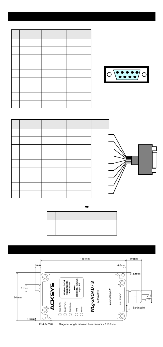
-Vérifiez l’interface électrique (RS232/RS422/RS485).
-Vérifiez les sens de connexion, auriez-vous interverti Tx et Rx ? Ou
AA’ et BB’ en RS485 ? Ou A et B en RS422 ? En cas de doute, vous
pouvez inverser les A et B d’un même signal sans danger électrique.
-Vérifiez la connexion Wi-Fi.
-Si vous utilisez un contrôle de flux, assurez-vous que les signaux de
contrôle correspondants sont au bon niveau.
-N’utilisez jamais de contrôle de flux matériel en RS422/RS485 : les
signaux de contrôle sont disponibles en RS232 seulement.
La liaison Wi-Fi ne s’établit pas
-Vérifiez que les paramètres Wi-Fi (SSID distinguant les majuscules,
mode 802.11, canal radio, sécurité) sont identiques sur les deux
appareils qui doivent communiquer.
-Vérifiez les conditions radio : distance entre équipements, position et
orientation des antennes, obstacles aux ondes radio, interférences sur
le canal radio.
-Essayez sans les paramètres de sécurité.
-Essayez un autre canal radio.
-Vérifiez le fonctionnement du produit avec ses paramètres par défaut.
Les voyants WLan Tx/Rx et Diag clignotent en mode infrastructure
-Un clignotement alternatif des voyants WLan Tx/Rx et Diag signifie que
le lien Wi-Fi ne s’établit pas. Voir question précédente.
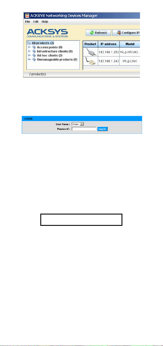
« ACKSYS NDM » ne trouve pas le produit
-ACKSYS NDM scanne seulement le réseau local. Les produits situés
derrière une passerelle ne seront pas vus.
-Si vous utilisez un pare-feu réseau, vérifiez qu’il ne bloque pas le port
UDP 17784 et le port SNMP (par défaut port UDP 161).
Comment restaurer les paramètres usine du produit ?
-Si le produit est accessible par l’interface web d’administration, vous
pouvez utiliser le navigateur pour restaurer la configuration.
-Sinon, ouvrez le boîtier, mettez le produit sous tension puis appuyez
sur le bouton reset au moins pendant 2 secondes. Relâchez et
attendez que le voyant Diag se rallume, signalant que le produit a
redémarré. La configuration usine a été restaurée.
BOUTONS ET SWITCHS
A l’intérieur du produit se trouvent plusieurs boutons.
Le bouton-poussoir RESET a trois fonctions : redémarrage, rechargement
de la configuration usine, démarrage du firmware « emergency upgrade ».
Le bloc SW4 (« settings ») a quatre interrupteurs :
-SW4-1 (mode normal OFF): sur ON, le port série ne peut pas être
utilisé normalement, il sert pour le « CLI ».
-SW4-2 et SW4-3: sur ON, la liaison RS422/RS485 est polarisée (utile
du côté maître d’un bus série multipoint).
-SW4-4: sur ON, la liaison RS422/485 est terminée par une résistance
(utile aux deux extrémités d’une liaison de grande longueur pour
améliorer la qualité du signal).
En mode RS232, SW4-2, SW4-3, SW4-4
doivent être en position OFF

-7-
CONNECTEURS
Connecteur série DB9 mâle
Pin
RS232
RS422
RS485 4 fils
RS485 2 fils
1 DCD
2 Rx
3 Tx TxB (B)
4 DTR RxB (B’) TxRxB (BB’)
5 GND C C
6 DSR
7 RTS
8 CTS TxA (A)
9 RI RxA (A’) TxRxA (AA’)
Connecteur interne cages à ressort
Pin
RS232
RS422
RS485 4 fils
RS485 2 fils Couleur
1 Rx
[1]
2 CTS TxA (A)
3 DSR
4 DCD
5 RI RxA (A’) TxRxA (AA’)
6 Tx TxB (B)
7 RTS
8 DTR RxB (B’) TxRxB (BB’)
9 GND C C
[1] Les couleurs des fils sont indiquées sur une étiquette collée à l’intérieur du produit sous le couvercle.
Connecteur d’alimentation 9 V – 50 V (J1)
Pin
Nom du signal Couleur
1 - (GND) Noir
2 +V Rouge
Le produit n’est pas sensible à une inversion des fils d’alimentation.
SPECIFICATIONS
Toutes les cotes sont exprimées en mm
Connecteur DB9
6 7 8 9
1 2 3 4 5

-8-
Alimentation
Source d’alimentation DC large plage de 9V à 50V, 4W max.,
3,6W typiques à 9V, protection contre les
inversions de polarité
Connecteur
câble 2 brins
Interface série
Fonctions
Port COM virtuel
Passerelle MODBUS/TCP
Passerelle UDP/série multipoint
Passerelle TCP/série point à point client
ou serveur
Type de ports
1 port RS232 (9 signaux) commutable en
RS422/RS485 2 ou 4 fils
Terminaison RS422/485
Commutable, 133 Ω
Connecteurs
DB9 ETTD (cages à ressort à l’intérieur)
Câble de connexion
30 cm
Interface Wi-Fi
Mode radio
IEEE 802.11a/h, 802.11b, 802.11g
Topologie réseau
Client infrastructure (avec point d’accès)
Client ad-hoc (ordinateur à ordinateur)
Chipset
ATHEROS AR5414
Débits
802.11a/h : 6 à 54 Mbps
802.11b : 1 à 11 Mbps
802.11g : 1 à 54 Mbps
Mode ATHEROS Super AG™ : jusqu’à
108 Mbps (ne fonctionne qu’entre
équipements ATHEROS)
Bande de fréquence 802.11a
5 GHz; 4.900 à 5.850 GHz
Bande de fréquence 802.11b/g
2.4 GHz; 2.300 à 2.500 GHz
802.11b
802.11g
802.11a
Puissance Tx en sortie de carte
radio 20 dBm @1-11M
20 dBm @6-24M
18 dBm @36M
17 dBm @48M
15 dBm @54M
20 dBm @6-24M
17 dBm @36M
16 dBm @48M
13 dBm @54M
Sensibilité en réception à
l’entrée de la carte radio -92 dBm @1M
-87 dBm @11M -90 dBm @6M
-70 dBm@54M -90 dBm @6M
-70 dBm@54M
Antenne 1 antenne 2dBi omnidirectionnelle
bi-bande avec connecteur RP-SMA
Sécurité WEP 64/128 bits, WPA-PSK, WPA2-PSK
Filtre MAC. AES/TKIP/WEP directement
prise en charge par la carte radio.
Caractéristiques mécaniques
Dimensions (hors connecteurs)
L x l x h = 115 x 64 x 35 mm
Poids
328 g sans antenne
Boîtier
IP 66, fonte d’aluminium
Gamme de températures
Etendue, -25°C à + 70°C
Voyants 5 LEDs : alimentation, lien Wi-Fi,
données série, RS422/485, diagnostic
Bouton poussoir (à l’intérieur)
Appui court : Reset
Appui long (> 2 secondes) :
Restauration paramètres usine
Pendant la mise sous tension :
Réinstallation d’urgence
Switch « admin »
(SW4-1, à l’intérieur)
OFF : position normale
ON : administration CLI par port série
Logiciel
Configuration
Configurateur Acksys NDM
Interface de configuration web avec
protection par login/mot de passe
Console sur port série (CLI)
Mise à jour du Firmware
Par navigateur web ou par Acksys NDM
SNMP
A venir

-9-
VOYANTS
Le produit dispose de cinq voyants (LEDs) permettant d’indiquer son état :
LED Couleur Description
WLAN
Tx/Rx(*)
Bleu
Ce voyant clignote lors de l’envoi ou de la réception
de données sur l’interface Wi-Fi.
Serial
Tx/Rx Vert Ce voyant s’allume lorsque des caractères sont émis
ou reçus sur le lien série.
RS422
/485
Vert
Ce voyant est allumé si vous utilisez une liaison
différentielle RS422 ou RS485.
Diag(*) Rouge
Après la mise sous tension ce voyant reste allumé
(moins de 10s) jusqu’à ce que le produit soit initialisé.
Si le voyant reste allumé fixement plus de 30
secondes à la mise sous tension, cela signifie que le
produit est en panne.
Par la suite il ind
ique soit des états particuliers
dépendants du service actif, soit des erreurs de
réception sur le port série.
En mode Administration par le port série, ce voyant
clignote deux fois par seconde continuellement.
Power Vert
Ce voyant s’allume si le produit est correctement
alimenté.
(*) Diag + Wlan Tx/Rx: Clignotement alternatif
Ce clignotement n’est significatif qu’en mode infrastructure. Il signifie que le
produit n’est pas associé au point d’accès ou que les clés WPA sont fausses.
CERTIFICATIONS
Le produit est conforme aux directives européennes :
N° Titre
1999/5/CE
Radio and Telecommunications Terminal Equipment
Directive (R&TTE)
73/23/CE Directive Basse Tension
2004/104/CE CEM véhicules motorisé
Cette conformité est présumée par la référence aux spécifications suivantes :
N° Titre
EN60950 Matériels de traitement de l’information – Sécurité
EN61000-6-2 Norme générique, émission en environnement Industriel
EN61000-6-4 Norme générique, immunité en environnement Industriel
EN301-489-17 CEM pour équipement radio 2.4GHz & 5GHz
EN300-328
Electromagnetic compatibility and Radio spectrum Matters
(ERM) ; Wideband transmission systems, 2.4 GHz ISM
band
EN301-893 Broadband Radio Access Networks (BRAN) ;
5 GHz high performance WLAN
MIL-STD-810F Méthodes 514.5 et 516.5 (chocs & vibrations)
UTAC E2
Attestation délivrée par l’UTAC (Norme CE pour les
équipements électroniques montés à bord des véhicules)
FCC Part 15 (Common testing standard for most electronic
equipment)

Documentation ref. DTFRUS041 rev A4 02/10/14
-1-
WLg-xROAD/S
Quick installation guide
Wi-Fi Multifunction serial port server for
rugged environment
Virtual COM port, MODBUS/TCP, point-to-point,
multipoint, UDP and TCP client/server
Cast aluminum housing
Protected against shocks and vibrations
Wi-Fi 802.11 a/b/g/h and Super AG™
RS232, RS422, RS485 serial port
Large range power supply DC 9 – 50 V
Extended operating temperatures -25° to +70°C
Before starting, please check the product kit parts listing:
One WLg-xROAD/S product,
This installation guide, printed,
One omnidirectional antenna, 2dBi, dual band,
One CD-ROM with extra software, application notes and
documentations.
Please contact your dealer if any item listed above is missing or damaged.
Before continuing, check for the latest documentation and software updates
on the www.acksys.fr web site.
You will need:
a PC equipped with Wi-Fi,
the CD-ROM to install the « Acksys NDM » software,
a web browser, IE7, Firefox or compatible,
JAVA version 6 or greater (internal version 1.6.0).
Copyright © 2014 by ACKSYS. Under the Law of March 11, 1957, the reproduction in
whole or in part of this work, by any means whatsoever, is prohibited without the prior
written consent of ACKSYS.
Disclaimer. This document does not constitute a contract. ACKSYS does not guarantee
its contents in any way and accepts no responsibility regarding the profitability of the
products described or their suitability for the user's needs. Under no circumstances can
ACKSYS be held responsible for any errors that may be contained in this document, or for
damages, no matter what their extent, that result from the supply, operation or use of the
products. In its ongoing efforts to improve its documentation, ACKSYS reserves the right
to revise this document periodically or to change all or part of its content, without incurring
any obligation to notify any party whatsoever.
10, rue des Entrepreneurs
Z.A. Val Joyeux
78450 VILLEPREUX - France
Phone: +33 (0)1 30 56 46 46
Fax: +33 (0)1 30 56 12 95
Web: www.acksys.fr
Hotline: support@acksys.fr
Sales: sales@acksys.fr

-2-
INITIAL CONFIGURATION
Summary:
Power up the unit
Establish the Wi-Fi connection
Install Acksys NDM
Give an IP address with Acksys NDM
Configure the final Wi-Fi and serial parameters
If needed, install Acksys VIP
Define the serial port cabling
Check the Wi-Fi link
Check the serial port usage.
We will now go into the details of each step.
1. Plug antennas
Plug the provided antenna into the RP-SMA connector.
2. Connect the power supply
See the “specifications” section about the characteristics of the power supply.
Earth grounding precautions
If you do not use an isolated power supply, connect the power supply
ground (0V) to the earth grounding of the product, to guard against
potential destructions due to ground reference differences with other devices.
The device has no ON/OFF switch. It turns on automatically when power is
applied. Check the “Power” LED turns on.
The DIAG led turns off after a few seconds when the device is ready (< 10s).
3. Establish the Wi-Fi link between the product and your PC
Use a PC equipped with a Wi-Fi card. Start the appropriate system utility to
detect Wi-Fi equipments around. You should see the product, which uses the
following default parameters:
-SSID: “acksys”
-No security
-Ad-hoc mode
-Radio channel 6 in 802.11b/g
If you do not have a computer equipped with Wi-Fi, you can configure the product
through its serial port. See section « CLI administration ».
If you do not see the product, check the radio conditions (antennas plugged,
correctly oriented, product near the PC, no obstacle to radio waves) then
proceed to next step in order to reset the product to its factory settings.
If the product is visible from your PC, establish the Wi-Fi connection. Skip the
next step.
4. Reset to factory settings (if necessary)
This step is needed only if the product is not accessible from your PC. See
the “How to restore factory settings?“ topic in the “Troubleshooting“
section. After the product reboot you should now see the product in the Wi-Fi
devices list. Otherwise check your PC configuration.
5. Install “Acksys NDM” and configure the IP address
On a PC in the LAN, install and run the multi-platform application ACKSYS
NDM found on the provided CD-ROM. You must have Java installed.
The product appears in a list with its default IP address 192.168.1.253. Select
it and click “Configure IP” then give it an IP address that is compatible with
your network. You can also activate DHCP. Apply the change and wait for the
product to reboot.

-3-
6. Run the WEB configuration interface
Click on the Web button to access the built-in web-based interface from your
web browser.
In order to change the configuration you must choose the Admin user.
No password is required by default.
You are directed to a general product status page. From there you can
navigate with the general menu bar (horizontal, below the banner) and a
submenu bar (vertical, on the left). The fundamental parameters are in the
“BASIC” menu and the “Wireless” and “Serial port” submenus.
The “HELP” menu describes the parameters shown in all the other menus,
and contains a detailed glossary.
The default factory settings are:
-“Ad-hoc” mode
-SSID: “acksys”
-No security (no WEP, no WPA, no WPA2, no MAC filter)
-802.11b/g mode
-Radio channel 6
-“Diversity” antenna mode
Observe local laws when choosing
radio channels
And for the serial port:
-Virtual COM (VIP)
-Automatic configuration (as specified by user application)
See the “Serial service type selection” section if you are unsure about
these options.
7. If required, install VIP, the COM port redirector
Install VIP only if you meet both of the following conditions:
-You will use the product from a Windows application
-And you configured the serial service as “Virtual COM (VIP)” or (less
common) as “TCP raw port server”.
VIP must be installed on the PC where the application using the virtual COM
port will run. VIP is provided on the CD-ROM.
8. Wire the serial port
The DB9 plug from the product can be used as RS232, RS422 (4 wires) or
RS485 (2 wires). Check the kind of interface your serial equipment uses. It
must match the configuration chosen through the browser. Refer to the
“Connectors” section for wiring information.

-4-
9. Check the Wi-Fi configuration
If the product is set to Infrastructure mode, the DIAG and WLAN LEDs will
blink alternatively until the product establishes a link to an access point with
the same SSID. You can check the Wi-Fi communication with Acksys NDM
or the “ping” command.
If difficulties arise, always test with security features disabled, since the use of
keys may add the possibility of other errors.
If the product is set to ad-hoc mode, the alternating blink of the DIAG and
WLAN LEDs is not meaningful. You can check the Wi-Fi communication with
the same methods.
10. Check the serial configuration
The checking methods depend strongly on your application, so we can give
only a general advice.
First, it is of no use to test the serial communication when you are in doubt
about the Wi-Fi communication. Begin by insuring this one.
Check that the “RS422/485” LED is in the expected state.
You can test the “Virtual COM (VIP)” service by running the VIP’s
“VIPConfig” utility. Refer to its online help. Use a console emulator
(Hyperterminal, Putty, Minicom, Kermit…, or ATTY provided on the CD-ROM)
to connect and send a few characters. If the “Serial Tx/Rx” LED blinks, the
service works correctly.
You can test the “TCP raw port server” service in the same way, but the
serial parameters are not taken from the application, but rather from the
settings of the product.
You can test the “MODBUS/TCP slave” service by running a MODBUS/TCP
supervisor. Look at the “Serial Tx/Rx LED” to check that the request frames
go to the serial port. Then check the reception of responses in the supervisor.
Perhaps you will have to adjust the timeouts in the supervisor and/or the
product.
The other services are commonly used to set up a so-called “virtual cable”
between two products. Refer to the application notes.
11. Install the device in its final location
Two holes allow the product to be mounted on a support. The device can be
installed outside and bears temperatures from –25°C (–13°F) to +70°C
(+158°F) with an IP66 protection level.
“CLI” CONFIGURATION
The CLI, for « Command Line Interpreter », allows you to configure the
product using a serial console or a terminal emulator. However we advise you
to use the WEB interface as far as possible, since it is more complete and
easier to use.
Open the case of the product. Push the switch n°1 on the four-switches block
towards the “ON” position. Connect the serial plug to a PC using a crossover
cable.
In administration mode, the serial port is in RS232, 2400 bauds, 8 bits, no
parity, 1 stop, no flow control. Use a terminal emulator with these parameters.
Upon power-up the product sends a banner and a prompt, and the DIAG
indicator blinks unevenly twice per second.
On the CD-ROM, refer to the “firmware” manuals (which describe the serial
services) to obtain the list of available commands.

-5-
SERIAL SERVICE TYPE SELECTION
The way you will use the product determines the serial service to activate.
Get help from the information provided on the “BASIC” page, “Serial port”
submenu.
If you are using the MODBUS protocol:
•use the “MODBUS/TCP master” service if the serial port of the product is
tied to the MODBUS master (the supervisor);
•use the “MODBUS/TCP slave” service if the serial port of the product is tied
only to slave devices.
If you want to access a remote serial device in the same manner as a
local port (including control signals):
•usually the “Virtual COM (VIP)” service on the device side and a COM port
redirector like VIP on the computer will do that.
If you want to exchange serial data (no control signals) between two or
more devices through the network:
•use the « UDP raw port server » service on all the serial attachments
involved;
•if you have only two devices, and not losing data is more important than
speed and network bandwidth, you must use « raw TCP server » on one
side, « raw TCP client » on the other side.
If you want to write a SOCKET application to access remote devices:
•use “Virtual COM (VIP)” if you must configure control signals remotely;
•use « raw TCP server » to handle unrelated devices;
•use « UDP raw port server » to broadcast to several devices at the same
time.
If you want a remote serial device to call into your application:
•use « raw TCP client ».
FIRMWARE UPGRADE
Getting the updates
The firmware upgrades are available on our web site in the form of a file with
a “.bin” extension or a compressed file containing a “.bin” file. You must copy
this file on your computer before proceeding to upgrade.
Upgrade methods
With Acksys NDM: select one or more products, click “Upgrade” and
follow the instructions. (Remark: Acksys NDM uses a TFTP server
embedded in the product, which is allowed by default in the “Tools” menu,
“firmware” submenu.
With the product WEB interface: In the “Tools” menu, “firmware”
submenu, follow the instructions.
In case of power breakdown during upgrade
Interrupting the upgrade may result in an invalid firmware. In this case the
product reboots with a special firmware called “emergency upgrade”.
This mode allows firmware reload. It has the following characteristics:
-The DIAG indicator blinks quickly and evenly
-The serial port cannot be used
-The Wi-Fi interface acts as an access point, B/G automatic channel
-An embedded DHCP server eases connection from the PC
-The advertised SSID is “emergency-upgrade”
-The product appears in Acksys NDM as “emergency upgrade”
-The WEB interface has only one page, which allows you to reload the
firmware.

-6-
TROUBLESHOOTING
None of the LED indicators turn ON
-Check the power supply (voltage, current).
-Check the cabling and the plug of the power supply cable.
The Serial Tx/Rx LED indicator stays OFF
-Check the electrical interface (RS232/RS422/RS485).
-Check the direction of the signals; did you exchange Tx and Tx? Or
AA’ and BB’ in RS485? Or A and B in RS422? In doubt, there is no
electrical risk to exchange the A and B wires of one signal.
-Check the Wi-Fi connection.
-If you are using flow control, check that the corresponding control
signals have the required level.
-Never use hardware flow control with RS422/RS485: the control
signals are available only with RS232.
The Wi-Fi link does not happen
-Make sure that both products involved in the communication are set to
the same Wi-Fi parameters (case sensitive SSID, 802.11 mode, radio
channel, security).
-Check the radio conditions: distance, placement and orientation of the
antennas, obstacles to radio waves, radio channel interferences.
-Temporary disable all securities and encryption settings.
-Try another radio channel.
-Try the product with its factory settings.
WlanTX/RX and Diag LEDs are flashing in infrastructure mode
-Alternatively flashing WlanTX/RX and Diag LEDs mean that the
product cannot link to the AP. See previous question.
“ACKSYS NDM” does not find the product
-ACKSYS NDM only scans the local network. Devices located behind a
gateway are not seen.
-If you use a firewall on your P.C, insure it doesn’t block UDP port
17784 and SNMP port (UDP port 161 by default).
How to restore factory settings?
-If the built-in web-based interface is reachable, you can use your
browser to restore factory settings.
-Else, open the case of the unit, power up the unit, and then hold down
the reset button for at least 2 seconds. Then release it and wait for the
Diag LED to light on again, meaning that the product rebooted. The
factory settings were restored.
BUTTONS AND SWITCHES
Inside the product case, there are several buttons:
The RESET pushbutton has 3 functions: reboot, reload factory settings, start
the emergency upgrade firmware.
The SW4 block (“settings”) has 4 switches:
-SW4-1 (normal mode OFF): if ON, the serial port cannot be used
normally, instead it displays the CLI.
-SW4-2 and SW4-3: if ON, the RS422/RS485 line is polarized (useful
on the master side of a multidrop serial bus).
-SW4-4: if ON, the RS422/485 line is terminated by a resistor (useful on
the two ends of a long cable, to have a better signal quality).
In RS232 mode, SW4-2, SW4-3, SW4-4
must be set to OFF.

-7-
CONNECTORS
Male DB9 serial connector
Pin
RS232
RS422/485
4 wires
RS485
2 wires
1 DCD
2 Rx
3 Tx TxB (B)
4 DTR RxB (B’) TxRxB (BB’)
5 GND C C
6 DSR
7 RTS
8 CTS TxA (A)
9 RI RxA (A’) TxRxA (AA’)
Internal spring clamp connector
Pin
RS232
RS422/485
4 wires
RS485
2 wires
Color
1 Rx
[1]
2 CTS TxA (A)
3 DSR
4 DCD
5 RI RxA (A’) TxRxA (AA’)
6 Tx TxB (B)
7 RTS
8 DTR RxB (B’) TxRxB (BB’)
9 GND C C
[1] The wire colors are indicated on the label attached to the inside of the product under the cover plate.
Power supply connector +9 – 50 V (J1)
Pin Signal name Color
1 - (GND) Black
2 +V Red
The product can handle power supply wires inversion.
SPECIFICATIONS
All dimensions are given in mm.
DB9 connector
6 7 8 9
1 2 3 4 5

-8-
Power supply
Power source Wide DC power range from 9V to 50V,
4W max, 3.6W typical at 9V, polarity
inversion protection.
Connector
2-wires cable
Serial interface
Functions
Virtual COM port
MODBUS/TCP gateway
UDP/serial multipoint gateway
TCP/serial point-to-point gateway client or
server
Type of ports
1 RS232 port (9 signals) switchable to
RS422/RS485 2 or 4 wires
RS422/485 termination
Switchable, 133 Ω
Connectors
DTE DB9 (spring clamp in the case)
Cable
30 cm (1 ft)
Wi-Fi interface
Radio mode
IEEE 802.11a/h, 802.11b, 802.11g
Network topology
Infrastructure client (with an access point)
Ad-hoc client (peer to peer)
Chipset
ATHEROS AR5414
Data rates
802.11a/h: 6 to 54 Mbps
802.11b: 1 to 11 Mbps
802.11g: 1 to 54 Mbps
ATHEROS Super AG™ mode: Up to 108
Mbps (works only when both ends are
using an ATHEROS chipset).
Frequency band for 802.11a
5 GHz; 4.900 to 5.850 GHz
Frequency band for 802.11b/g
2.4 GHz; 2.300 to 2.500 GHz
802.11b
802.11g
802.11a
Tx output power (Radio card
output) 20 dBm @1-11M
20 dBm @6-24M
18 dBm @36M
17 dBm @48M
15 dBm @54M
20 dBm @6-24M
17 dBm @36M
16 dBm @48M
13 dBm @54M
Rx sensitivity (Radio card input) -92 dBm @1M
-87 dBm @11M
-90 dBm @6M
-70 dBm@54M
-90 dBm @6M
-70 dBm@54M
Antenna 1 Omni-directional 2dBi dual-band
antenna with RP-SMA connector
Security
WEP 64/128 bits, WPA-PSK, WPA2-PSK,
MAC filter. AES/TKIP/WEP handled
directly by the radio card hardware.
Mechanical characteristics
Dimensions (w/o connectors)
L
x
w
x
h = 115
x
64
x
35 mm (4.6
x
2.5
x
1.4 in)
Weight
328 g (12 oz) without antenna
Enclosure
IP 66, cast aluminum housing
Operating temperatures
-25°C to + 70°C (-13 to +158°F)
Status indicators
5 LEDs: Power supply, Wi-Fi link, serial
data, RS422/485, diagnostic
Push button
Quick push: Reset
Long push (> 2 sec.):
Restore factory settings
During power up:
Force emergency upgrade
Admin switch
(internal SW4-1)
OFF: normal position
ON: serial port CLI administration
Software
Configuration
Acksys NDM configurator
Built in web based interface with
username/password protection scheme
Serial port command line interface (CLI)
Firmware upgrade
Via web browser or Acksys NDM
SNMP
Soon

-9-
LEDs definition
5 status LED display the state of the product:
LED Color Description
WLan
Tx/Rx(*)
Blue Flashing for WLAN Tx/Rx activity.
Serial
Tx/Rx
Green
This led blinks when sending or receiving data on the
serial link.
RS422
/485 Green This led is ON when you use a differential (RS422 or
RS485) electrical interface.
Diag(*) Red
After power up this led stays on until the product is
operational (less than 10s).
If the led stays on steadily more than 30 seconds at
power up, the product is out of order.
After boot-
up it indicates either special states
depending on the active service, or reception errors
on the serial port.
In serial port administration mode, this led blinks twice
per second, indefinitely.
Power Green
This led is ON when the power supply connector
correctly powers the product.
(*) Diag + Wlan Tx/Rx: alternative blink
This blink is meaningful only in infrastructure topology. It means that the
product did not yet associate with an access point, or WPA keys are wrong.
Regulatory compliance
The unit conforms to the following European Council Directives:
N° Title
1999/5/CE Radio and Telecommunications Terminal Equipment
Directive (R&TTE)
73/23/CE Low voltage directive
2004/104/CE EMC for motor vehicles
The device has been certified to comply with the European directives and is
appropriately CE marked.
N° Title
EN60950 Data processing devices – Security
EN61000-6-2 EMC emission, industrial grade
EN61000-6-4 EMC Immunity, industrial grade
EN301-489-17 EMC for radio equipment 2.4Ghz & 5GHz
EN 300 328 Electromagnetic compatibility and Radio spectrum
Matters (ERM); Wideband transmission systems, 2.4
GHz ISM band
EN 301 893 Broadband Radio Access Networks (BRAN);
5 GHz high performance WLAN
MIL-STD-810F Shocks & vibrations according to 514.5 and 516.5
methods
UTAC E2
CE standard for electronic equipments installed aboard
vehicle
FCC
Part 15 (Common testing standard for most electronic
equipment)
Table of contents
Languages:
Popular Automobile Accessories manuals by other brands

Kenway
Kenway 64274 Owner's manual & safety instructions

Havis-Shields
Havis-Shields C-VS-0812-CHGR Install instructions

Thule
Thule Kit 1113 Fitting instructions

Fiamma
Fiamma F80s Installation and usage instructions

Cequent Towing Products
Cequent Towing Products 24756 installation instructions

Manta
Manta MM310H user manual