ACL 780/781 Operation Manual Rev. March 16, 2018, MKB
Page 7 of 13
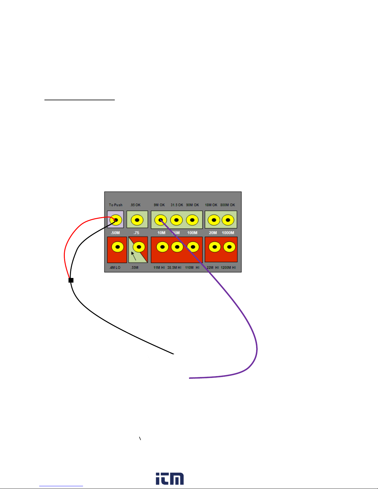
CALIBRATION CHECK
The ACL 780/781 Economy Combo Tester can be adjusted to various electrical resistance specifications
(limits) depending on what test standard (i.e. ESDA for US and CECC for Europe) the user follows or what
a company requires. To change settings, open the ACL 780/781 Economy Combo Tester and adjust the
dip-switches to desired resistance value. (See below for values.)
If calibration traceable to NIST is desired, send to the ACL Meter Department in order to determine and
trace accuracy. Remember the ACL 780/781 Economy Combo Tester cannot be calibrated. The meter’s
accuracy can only be checked. The meter has resistor and capacitor on the circuit board. Every time the
tester is used, it self-calibrates against this 1% resistor.
1. Purchase 1% resistors on each side of the resistance value that is set in the meter. Factory
settings (in bold) require the following resistors.
a. Foot Low (.75M) 675k & 825k
b. Wrist Low (.75M) 675k & 825k
c. Foot High (100M) 90M & 110M
d. Wrist High (10M) 9M & 11M
2. Solder, clip or twist wires to both ends of the resistors.
a. Attach one end of the resistor to the stainless steel button on the front of the meter
using an alligator clip and piece of aluminum tape. Alternatively, the banana plug can
be held to the button.
b. Attach the other end of the resistor to the receptacle that is being tested using the
appropriate plug attachment: banana plug or stereo plug for wrist, stereo plug for
testing footplate. When the feet are checked, both the right and left leg of the circuit
must have a load on the wire. If not, the unloaded leg will buzz. To accomplish this, a
stereo plug with two pigtail wires must be used. Each of these two wires must have a
resistance load on one end. The other end must be attached to the button using an
alligator clip and piece of aluminum tape or help to the button.
3. To begin test:
a. Position selector switch to “Wrist”setting when testing the wrist limits or the “Foot”
setting when testing the foot limits. Remember when testing feet a stereo plug is
inserted into the jack that usually has the foot plate plug inserted. The other end has the
resistor attached.
b. When testing wrist limits, plug resistor in wrist strap plug-in. When testing foot limits,
insert two resistors into the plug-in jack usually used for the foot plate.
4. Press the test button and compare to the resistance range to be calibrated.
5. Release the test button and compare the pass or fail response to limits being tested.
6. Since the meter is self-calibrating and self-zoning there is no adjustment necessary.
www. .com information@itm.com1.800.561.8187