CCTS-03
CCTS-03
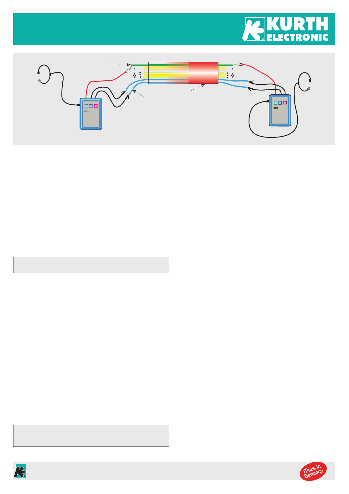
Shield / metallic sleeve
1
2
3
1
2
3CABLE
Free double wire
Wire under test
SET A
SET B
To find earth faults, the screen or cable sheath
must be earthed. The red test lead must then be
additionally connected to earth on the
transmitter side (TX).
ATTENTION! Do not use this connection for tests
on connected copper pairs!
A
B
1
1
2
2
RX
TX
SET A
SET B
Operating manual
Cable Conductor Test Set CCTS-03
The CCTS-03 cable conductor testing device is used to check conductors
for continuity, interchanging, interruption and earth fault. Due to micropro-
cessor-controlled technology, testing on active analogue and ISDN lines with
or without xDSL is possible for the fi rst time. Simple and robust push-button
control with LED display simplifi es operation in the fi eld. Automatic switch-off
after approx. 100 min. prolongs battery life.
Start-up of the Cable Conductor Test Set
Connecting the devices
First, the headset is connected to CCTS-03 via the headset jack . CCTS-03
is switched on by pressing the ON/OFF key >30 ms. The ON LED fl ashes
rapidly. In this mode, the talk function is activated. A free pair of wires is
connected to the black banana sockets as a voice pair via the black test
leads, the polarity does not have to be observed. If earth fault testing is also
required, the test lead for the TX unit must also be grounded.
At the far end, connect the second CCTS-03 as well as the fi rst device.
Voice connection is now active.
The red test cord is plugged into the red socket. One device must be set as
encoder (TX) and one device as evaluator (RX). This is done by pressing
and holding the RX/TX key for more than 2 seconds. The LEDs RX and TX
will be switched on and off one after the other. To activate the desired mode,
the key must be released according to the LED. The LED then starts fl ashing
slowly to indicate the active mode. There is no need to make any further
settings for the device in TX mode.
Testing on free / unconnected wires
The device in RX mode is automatically adjusted to the maximum possible
line resistance after switching on the RX mode and can normally be used for
testing (unswitched wires) immediately without any additional adjustment.
Testing on live / connected wires
Since the resistance diff erence between A- and B-wire is very small for con-
nected wire pairs, especially with ISDN-connected wires, it was impossible
to diff erentiate between A and B so far. The CCTS-03 cable conductor tester
therefore has the possibility to carry out a microprocessor-controlled adjust-
ment. To activate it, proceed as follows: The probes are connected with a
reference wire on both sides. This can be a free or occupied wire. Because
the CCTS-03 analyzes resistance diff erences smaller than <100 Ω, a good
conenction must be ensured
After applying the test probes to the wire to be tested (test tone must be
audible!), press the Auto Adjustment button on the instrument in RX mode
>1 sec until the RX LED starts fl ashing rapidly. Release the button. The RX
LED fl ashes rapidly during the entire adjustment process.
If the wire to be tested is not found or the calibration cannot be carried out for
other reasons (cable resistance too low <20 Ω or too high >3 kΩ, test probe
removed too early, or similar), a warning tone consisting of three short tones
sounds in the handset. Then the adjustment may have to be repeated. If this
is repeatedly negative, the connected twisted pairs must be separated at the
MDF and, if necessary, at the DMARC.
Automatic adjustment for connected wires
After placing the probe on the wire to be tested, press the Auto Adjustment
button in RX mode on the device >2 sec. The adjustment process starts after
releasing the key. The RX LED fl ashes rapidly during adjustment. If the wire
to be tested cannot be found, a warning tone consisting of three short tones
sounds in the speaker. If it is the correct wire, the test tone sounds once for
approx. 1 second, then stops for approx. 1 second and then comes as a
constant tone. Only then is the device adjusted.
If the probe is removed, the test tone stops. If the test tone is not stable,
i. e. arrives with interruptions (stuttering) or if other wires also receive the
test tone without an error (e. g. switched ISDN lines), it can be fi ne-tuned
by briefl y (<2 sec) pressing the +and -keys. Normally you only have to
adjust in the direction minus (-) as CCTS-03 always adjusts a little more in
the direction +. This adjustment is usually only necessary in extreme cases.
Manual readjustment
If the test tone does not arrive stable on the wire to be tested, i. e. with
interruptions (stuttering), the evaluation is at the lower limit. Pressing the
+ button (<1 sec) once or twice briefl y shifts the evaluation threshold, thus
stabilizing the tone.
If the test tone on the wire to be tested is evaluated in a stable manner and
the test tone arrives with stuttering on adjacent wires, the evaluation is at
the upper limit. By pressing the - button (<1 sec) once or twice, the eva-
luation threshold is moved downwards and the tone on the adjacent wire
disappears.
After each manual adjustment, check again whether the tone on the wire
to be tested is still stable. This adjustment is usually only necessary in
border areas.
If, however, the test tone is permanently received (without interruption) on
other wires despite readjustment, there may be a cable fault which must be
checked for with the corresponding measuring instruments.
Testing the wires
Switch on both units as described and adjust if necessary. When the voice
connection is established, Aconnects the red test cord with the wire to be
tested and notifi es Bof this. If this wire has a touch to another wire or if it is
interchanged, the sound becomes audible. If there is no sound, Bplaces his
probe on the announced wire. If this is continuous, the sound becomes
audible. Bnow informs Athat his probe is „on“. Anow changes its probe
tip to the next wire to be tested in the cable. No sound may be heard yet.
He communicates the request of the probe tip again to B, which now also
applies the probe tip to the announced wire. In this way, a higher-pair cable
can be checked quickly and easily.
Attention: The speech connection must be routed via a free pair of
wires!
If the adjustment is successful, the green LED stops fl ashing quickly
and the test tone is continuously audible. Only then is the device
adjusted and the probes can be removed from the reference wire.
Kurth Electronic GmbH | Muehleweg 11 | D 72800 Eningen u.A. GERMANY | Tel. +49(0)7121 9755 0


