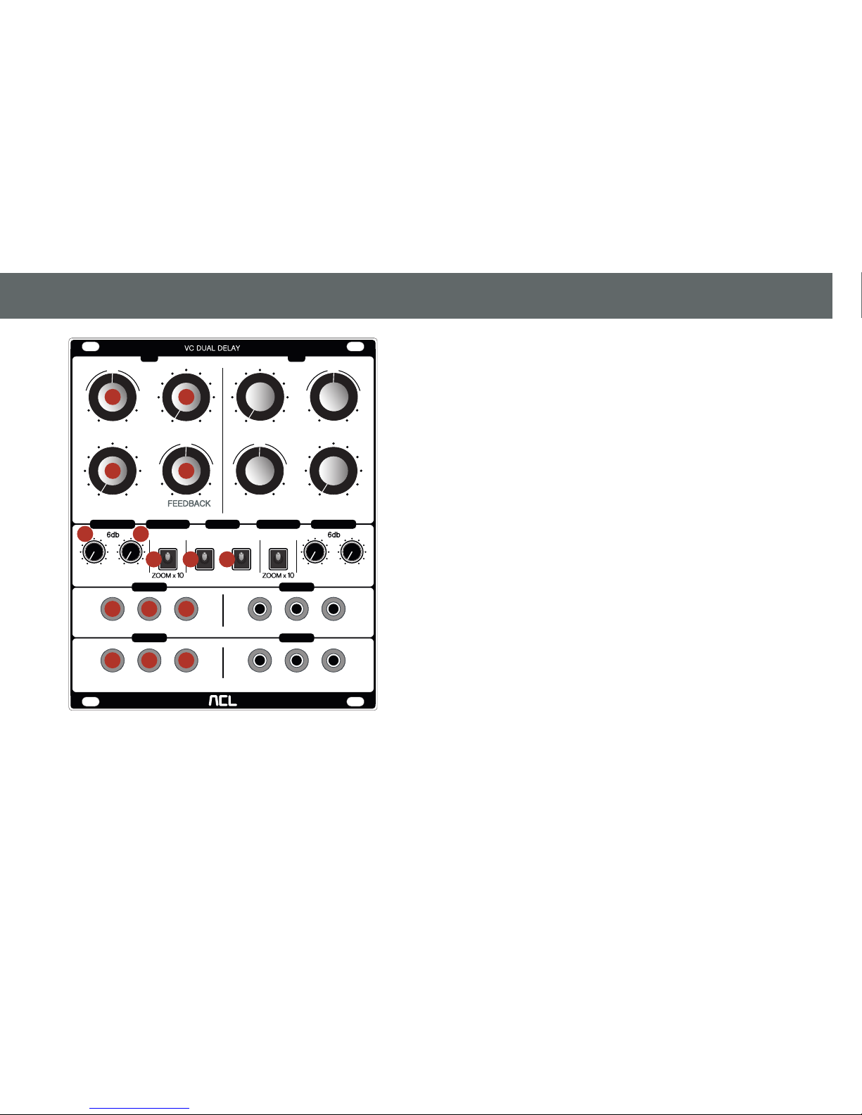
ACL VC Dual Delay User manual

VC Dual Delay
User’s Manual
Eurorack Synthesizer Modules 21HP

TABLE OF CONTENTS
1.INTRODUCTION
2.WARRANTY
3.INSTALLATION
4.FUNCTION OF PANEL COMPONENTS
5.CHARACTERISTICS
6.FEEDBACK ROUTING
7.SPECIFICATIONS
2

1. INTRODUCTION
Audiophile Circuits League.-VC Dual Delay consists of 2 equal, independent
delays A and B, each with its own feedback loop, each contains a 6dB HP and a
6dB LP �ilter (not VC), but the internal feedback loop can be opened by patching
a cable into the “IN FB” - jacks to route other signal-processing modules into the
feedback-loop. Please note that there is no “Dry-Signal”-path. By designing the
module, we thought, it would be mostly used in combination with other modules
to achieve some echoes and reverberated ambience, one could put one delay in
the feedback-path of another delay for example – there are many different
routing con�igurations, achieving strange modulated reverberated space by
combining several Dual VC Delay-modules in various manner.
Due to its vast �lexibility, the module offers load´s of possibilities for
hours-longing sessions of mangling signals, pitch modulation and the generation
of fantastic ethereal outer galactic spaces.
Used in parallel / stereo-mode, it generates voltage controlled modulated spatial
effects with its own special character. The sound of the Princeton PT2399 delay
chip often reminds for BBD-circuit´s which principle in fact shares similarities
with the function of the PT2399 chip. Because the audio - and CV - input´s are
normalized in the scheme of A→B, the module is following your needs for many
different patching situations easily. The sonic possibilities of using several
module together can be mind blowing, especially when the almost endless
possibilities of different feedback-routing are explored.
(For details about normalization, see 5. CHARACTERISTICS section)
3

2. WARRANTY
In the event of a fault in use, we will repair or replace it free of charge under the
warranty terms stated below. The warranty period is valid for one year from the
day of purchase. If repair is necessary, please attach the warranty card to the
product and ask the dealer you purchased it from or our company.
The Warranty card can not be reissued. The Warranty card is valid only in the
country where you purchased. We can not guarantee the incidental damage
caused by the breakdown or damage that occurred during use of this product. In
addition, we can not guarantee when the fault falls under the following
conditions.
· Failure / damage caused by use of unspeci�ied power supply / accessories.
· Failure / damage caused by incorrect connection or use of power cable.
· Failure / damage caused by improper handling method.
· Failure / damage caused by natural disasters (�ire, �looding etc.) and
pollution.
· When the cause of breakdown or damage lies in equipment other than this
product.
· Failure / damage caused by improper modi�ication, adjustment, parts
replacement.
· Failure / damage when used under particularly severe conditions, when
loaned/rental/hired out to 3rd party.
· When replacing expendable items such as battery.
· When there is no presentation of warranty card.
· When the warranty card has not been fully completed, or when it has been
Is it a malfunction?
Please read the user's manual carefully and checking again. If you think that
there is still a problem, please consult with the dealer you purchased from or
contact us (English) .
4

3. INSTALLATION
⚠WARNING
*Always turn the Eurorack unit off and unplug the power cord before pluging
the Eurorack power cable.
*When attaching the Eurorack power cable, please be careful not to touch the
terminal part.
Connect to the Eurorack's system power supply (+ 12V) using the supplied
Eurorack power cable.
Connect the 16-pin connector to the Eurorack power connector. Connect the red
mark on the power cable so that it matches the pin on the (- 12 V) side of the
power connector.
Connect the 10 pin connector to this product side. Projection is provided for the
10-pin connector to prevent connecting the included power cable incorrectly in
the reverse direction. Please connect so that the projection of the power cable
and the indentation of this product side connector match.
Projection
Red line
To Module To Power
Connector
GATE
CV
+5V
+12V
GND
GND
GND
-12V
FIG.1:Eurorack power cable
5

4. FUNCTION OF PANEL COMPONENTS
FEEDBACK FEEDBACK
VC DUAL DELAY
6db 6db
DELAY
CV
A
FILTER B
FILTER A
IN A
OUT A
IN B
OUT B
ROUTE
B
NORM NORM
FEEDBACK
PAR
PAR
SER
RATE CV RATE CV
RAT E
IN
RAT E
IN
DELAY
FLT FB FB FLT FB
CV
FB DELAY
FB
LO CUT HI CUT LO CUT HI CUT
CV ZOOM
C
-
+
C
-
+
C
-
+
C
-
+
FB
DELAY DELAY
CROSS
CV ZOOM
A B
①“RATE CV” knob
This is the Attenuverter for the CV signal input from the ⑫"IN CV" jack.
②“RATE” knob
This knob is adjusting the internal sampling rate of the internal delay circuit.
Knob turned clockwise means higher sampling rate and therefore a shorter
delay time and higher audio �idelity and vice versa.
③“IN” knob
Adjust the amount of the audio signal from the ⑩"IN" input jack for delay
processing. Audio input is not performed when knob is completely closed. As a
result, the sound output from the delay will also be muted. Please take care of
the level of the input signal in order to avoid distortion due to overdriving the
delay circuit.
④“FEEDBACK” knob
If a patch cable plugged in to the ⑪“IN FB” input jack, the internal feedback-loop
will be opened so you can build your own feedback-loop using either the ⑭
“FILT FB OUT” output jack or the ⑮“FB OUT” output jack, including patching
other modules inside of it, I.E. phase-shifters, �ilters, other delays, VCA´s (to be
able to control the depth of the feedback by a control voltage) and so on. The
amount of the feedback still can be controlled by the ④“FEEDBACK” knob
(negative or positive).
2
34
5 6
7 8 9
10 11 12
13 14 15
1
FIG.2:Front Panel
6

⑤“LO CUT” knob
This knob controls the cutoff frequency of the built-in -6 dB/Oct-sloped low cut
�ilter, which is – along with the HI CUT in series - �iltering the output signal of
Delay A before it´s fed back into the input of Delay circuit A (independent
feedback loop for each delay circuit) or Delay B (crossfeedback mode)
dependent from the position of the feedback switch, and also routed to the ⑭
“FLT FB OUT” output jack.
Independent LO CUT and HICUT �ilters are both prepared for Delay A and B.
⑥“HI CUT” knob
This is a -6 dB / oct high cut �ilter internally routed in series with the LO CUT
�ilter (as described above).
⑦“CV ZOOM” switch
Select the CV resolution of ①"RATE CV" knob with this switch. By setting it to
X 10, the resolution becomes ten times �iner.
⑧“PARALLEL/SERIAL” switch
Switch between parallel mode and serial mode. Select whether to use Delay A
and B separately in parallel mode or continuously in serial mode.
⑨“FEEDBACK PARALLEL / CROSS” switch
The feedback outputs of Delays A and B can be switched in parallel mode (Delay
A and B have it´s own independent internal feedback path) or cross mode(Delay
A is internally fed back into and B vice versa). (See FIG. 3)
DELAY A
OUT
DELAY B
OUT
DELAY A
OUT
(
8
-pattern of feedback)
A→B & B→A
DELAY B
OUT
FEEDBACK
X
PAR
FEEDBACK
X
PAR
FB B
FB B
FB A
FB A
FIG.3:Variety of feedback output by switching FEEDBACK
PAR / CROSS switch
7

⑩“DELAY” input jack
Input the audio signal for delay processing.
⑪“FB” input jack
If a cable is inserted into this jack, the internal feedback-loop will be opened and
the signal coming will be summed with the signal coming into ⑩“IN” internally,
before routed into the input of the delay circuit.
(please refer to: ④“FEEDBACK” knob)
⑫“CV” input jack
Input to control the delay time with the CV signal. ①"RATE CV" knob functions
as an attenuverter.
⑬“DELAY” output jack
It outputs the delayed signal.
⑭“FLT FB ” output jack
It outputs the delayed signal, but behind the following HI CUT and LO CUT �ilters
(refer to the description about the HI CUT and LO CUT �ilters).
⑮“FB ” output jack
It outputs only the feedback after the delay processing. That means WET 100%.
It is common to mix with the original sound by an external mixer.
8

5. CHARACTERISTIC
All audio · CV input signals are normalized (interconnected) from delay A to B.
“Normalization” means that audio / CV signals are automatically duplicated
from delay A to delay B when no cable is inserted on the delay B side. In other
words, it is possible to control and process both A and B delays from one cable
input (See FIG.4). This feature economizes the need to duplicate signals using
external multiple modules.
Conversely, when inputs A and B are performed using two cables, it is possible
to independently control and process Delay A and B (See FIG. 5).
Input jack A (Audio & CV)
Delay A Delay B
FIG.4: When only input A is plugged in (Normalized) FIG.5: When inputs A and B are plugged in (not Normalized)
Input jack A & B (Audio & CV)
Delay A Delay B
A B
9

FIG.6: Feedback routing (Parallel Routing)
6. FEEDBACK ROUTING
LO CUT
HI CUT
Filter A
Delay B
+
Mix
Mix
Delay A
IN B
IN A
FEEDBACK A
FEEDBACK B
LO CUT
HI CUT
Filter B
PAR
Feedback Route
IN A
IN B
IN FB A
IN FB B
Normalisation
Normalisation
FLT FB
OUT A
FLT FB
OUT B
OUT A
OUT B
+
parallel
Switch to PAR !!
FB OUT B
FB OUT A
10

FIG.7: Feedback routing (Cross Routing)
CROSS
LO CUT
HI CUT
Filter A
Delay B
+
Mix
Mix
Delay A
IN B
IN A
FEEDBACK A
FEEDBACK B
LO CUT
HI CUT
Filter B
CROSS
Feedback Route
IN A
IN B
IN FB A
IN FB B
Normalisation
Normalisation
FLT FB
OUT A
FLT FB
OUT B
OUT A
OUT B
+
Switch to CROSS !!
FB OUT A
FB OUT B
11

7. SPECIFICATIONS
Power
Eurorack system power supply
Width
21 HP
Depth
22mm
Power consumption
Ca. 40mA on -12V / ca. 85mA on +12V
Accessories
· Eurorack power cable x1
· Mounting screws x4
12
ACL-E-DD-
1707
-
1
Table of contents
Other ACL Recording Equipment manuals