FJELLCOM AP Polygard Multi Sensor Board User manual

GAMSB_E_0220
PolyGard2 Multi-Sensor Board Cxxx
Sensor Board for connection of up to three Sensor Cartridges (analog/digital)
SerialNo.
User Manual
February 2020/

User Manual - Multi-
Sensor Board Cxxx
Page 2
GAMSB_E_0220
1Intended Use ...................................................................................................... 3
2Functional Description ....................................................................................... 3
2.1 General ....................................................................................................................................................... 3
2.2 Measuring Mode....................................................................................................................................... 3
2.3 Special Mode............................................................................................................................................. 3
2.4 Function Outputs ..................................................................................................................................... 4
2.5 Relay Mode................................................................................................................................................ 4
2.6 Relay Function Static / Flash ................................................................................................................. 4
2.7Horn Function (not safe output circuit because resettable) ......................................................... 4
3Installation......................................................................................................... 5
3.1 Mounting Instructions............................................................................................................................. 5
3.2 Installation Work...................................................................................................................................... 5
4Electrical Connection ......................................................................................... 6
4.1 Wire Connection ...................................................................................................................................... 6
4.2 Connection Diagram................................................................................................................................ 7
5Commissioning .................................................................................................. 8
5.1 General Notes ........................................................................................................................................... 8
5.2 Optical Check............................................................................................................................................ 8
5.3 Selection Gas Type with Unit ................................................................................................................ 9
5.4 Installation of Sensor Cartridge SC2 ................................................................................................... 9
5.5 Addressing of SC2.................................................................................................................................... 9
5.6 Registration/Assignment of the Sensor Cartridge(s) (SC2) ........................................................... 9
5.7 Calibration ...............................................................................................................................................10
5.8 Calibration with DGC-06 Software PCE06.......................................................................................10
5.9 Exchange of Sensor Cartridge SC2 ....................................................................................................11
6Inspection and Service ..................................................................................... 12
6.1 Inspection ................................................................................................................................................12
6.2 Service and Calibration ........................................................................................................................12
6.3 Trip Test with Reference Gas ..............................................................................................................12
7Project protection ............................................................................................ 12
8Troubleshooting............................................................................................... 13
8.1 Multi-Sensor Board................................................................................................................................13
8.2 Sensor Cartridge (Messages at the Tool / Controller)...................................................................13
9Technical Data.................................................................................................. 14
9.1 Multi-Sensor Board (MSB) ....................................................................................................................14
10 Figures ............................................................................................................. 15
11 Part Disposal .................................................................................................... 16
12 Notes and General Information ........................................................................16
12.1 Intended Product Application.............................................................................................................16
12.2 Installers’ Responsibilities ..................................................................................................................16
12.3 Maintenance............................................................................................................................................16
12.4 Limited Warranty ...................................................................................................................................16

User Manual -
Multi-Sensor Board Cxxx
Page 3
GAMSB_E_0220
1Intended Use
The PolyGard2 Multi-Sensor Boards (for connection of max. three sensor heads) are designed for the
detection of toxic, combustible or dangerous atmosphere in many commercial and industrial applications in
connection with the Gas Controller System DGC-06.
The intended sites are all areas being directly connected to the public low voltage supply, e.g. residential,
commercial and industrial environments as well as small enterprises (according to EN 50 082).
The PolyGard2 devices must not be used in potentially explosive atmospheres. The device must only be
employed in areas within the environmental conditions specified in the Technical Data.
2Functional Description
2.1 General
The Multi-Sensor Board can manage up to three sensors in total, two of them may be different Sensor
Cartridges of the SC2 series via local bus and/or up to three of them analog sensors with 4–20 mA signal
(MC2 series).
Connection to Cxxx
SC2 sensors via local bus
MC2 sensors with 4–20 mA signal
Number
0
1–3
Number
1
0–2
Number
2
0–1
Table: Connection possibilities of sensors to the Cxxx
The function of the sensor series SC2 or MC2 is not the subject of this User Manual but can be found in the
operating instructions SC2/MC2.
The Cxxx provides the power supply of the SC2(s) and makes the measured data available for digital
communication and for the 4 to 20 mA output. Communication with the DGC06 controller takes place via the
RS 485 field bus interface with DGC06 protocol. The alarm relays can be controlled both via the DGC 06
controller and locally via the measurement signals. The digital input for acknowledgment or test function
and other options such as display or various communication protocols for direct connection to superordinate
BMS ensure the adaptation to the wide range of applications in gas detection technology.
The Multi-Sensor Board is integrated in the system as a slave with its basic address. The addressing on the
field bus level as well as the registration and assignment of the Sensor Cartridge on the local bus level is
done via the Service Tool STL06 or with the DGC-06Software PCE06, which is directly connected to
the Cxxx. The cable topology for the RS-485 field bus can be taken from the “Guidelines for wiring
and commissioning of the DGC-06 hardware”.
2.2 Measuring Mode
The sensor element continuously monitors the ambient air to detect an existing gas concentration and
transmits a measurement signal which is proportional to the gas concentration via the amplifier directly to
the AD converter of the µController. The µController checks the measurement signal for plausibility (within
defined measuring, temperature and voltage ranges, etc.), calculates the average and sends both values with
the attributes of gas type and unit via the local bus to the µController of the Multi-Sensor Board. The Cxxx
(slave) sends the data of the registered Sensor Cartridge upon polling request to the GC-06Controller
(master).
2.3 Special Mode
If a fault occurs (measurement signal, temperature or operating voltage outside the defined range,
communication error on local bus) or when the Multi-Sensor Board is in the maintenance/calibration mode,
the measurement operation is interrupted and the status of "special mode" is sent to the GC-06 Controller.
The integrated measuring amplifier converts this change in resistance into a linear output signal. The
continuous combustion leads by-and-by to a loss of sensitivity that can be compensated by performing
regular calibration of zero and gain. See from section 5.7.

User Manual -
Multi-Sensor Board Cxxx
Page 4
GAMSB_E_0220
2.4 Function Outputs
SHORT DESCRIPTION OF THE FUNCTION: DIGITAL OUTPUTS WITH THREE RELAYS
Action
Reaction
Relay 1
(Alarm1)
Reaction
Relay 2
(Alarm2)
Reaction
Warning
light
(Alarm 2)
Reaction
Horn
(Alarm 2)
Reaction
Relay 3
(Alarm2 +
fault)
Reaction
LED
Sensor signal < alarm threshold 1
OFF
OFF
OFF
OFF
ON
GREEN
Sensor signal > alarm threshold 1
ON
OFF
OFF
OFF
OFF
RED
Sensor signal > alarm threshold 2
ON
ON
ON
ON
ON
RED
Sensor signal alarm threshold 2,
but button Horn OFF activated
OFF
ON
OFF after
delay ON
RED
Measuring signal < (alarm
threshold 2 - hysteresis) but >=
alarm threshold 1
ON
OFF
OFF
OFF
OFF
RED
No alarm, no fault
OFF
OFF
OFF
OFF
ON
GREEN
No fault, but maintenance due
OFF
OFF
OFF
OFF
ON
GREEN
flashing
Internal error
OFF
OFF
ON
OFF
OFF
YELLOW
Note 1: Status OFF = Relay is configured “Alarm ON = Relay“ or the Cxxx is free from tension.
Note 2: Alarm thresholds can have the same value, therefore the relays and/or the horn and flashlight can be triggered together.
2.5 Relay Mode
Definition of the relay operation mode: The terms energized/de-energized come from the terms energized
or de-energized to trip principle (open circuit / closed circuit principle) used for safety circuits. The terms
refer to the activation of the relay coil, not to the relay contacts (as they are executed as a changeover
contact and available in both principles).
The LEDs attached to the modules show the two states in analogy. (LED off -> relay de-energized)
2.6 Relay Function Static/Flash
Definition of the relay function: The function "flashing" represents a connection option for warning devices
to improve visibility. If” flashing” is set, this must not be used as a safe output circuit anymore.
A combination of relay mode energized with flashing operation makes no sense and is therefore suppressed.
2.7 Horn Function (not safe output circuit because resettable)
The horn function is considered active if at least one of the two parameters (time or assignment to digital
input) is set. The horn function retains its functionality even for alarms in latching mode.
Special function: Recurrence of the horn relay
After an alarm has been triggered, the horn will remain active until it is acknowledged. After
acknowledgment of the horn relay/s (clicking a button or via external input) a timer starts. When this time
has run out and the alarm is still acting, the relay is set again. This process is repeated endlessly as long as
the associated alarm remains active.
Alarm2
Relay2
Gasconcentration higher lower than threshold
Acknowledging-
signal
On
Off
On
Off
On
Off
Time Time

User Manual -
Multi-Sensor Board Cxxx
Page 5
GAMSB_E_0220
3Installation
Electronics can be destroyed by electrostatic discharge (ESD). Therefore, the installation work
should be done only by persons connected to ground, e. g. with a wrist strap connected to
ground or by standing on a conductive floor (acc. to DIN EN 100015).
3.1 Mounting Instructions
The housing with the Multi-Sensor Board comes in closed state. Therefore, before mounting, break out the
pre-embossed knockouts to insert the cable entries and the Sensor Cartridge(s). The housing offers different
mounting options by a variety of knockout openings depending on the number and types of Sensor
Cartridge(s).
Prior to breaking out the knockouts it is essential to determine the exact position and size of the Sensor
Cartridge(s) and cable entries with reference to the drawing "Knockouts in housing A", fig. 1.
When choosing the mounting site please pay attention to the following:
•The mounting height depends on the relative density of the gas type to be monitored.
•Choose mounting location of the sensor according to the local regulations.
•Consider ventilation conditions! Do not mount the sensor near the airflow (air passages, suction
holes etc.).
•Mount the sensor at a location with minimum vibration and minimum variation in temperature
(avoid direct sunlight).
•Avoid locations where water, oil etc. may influence proper operation and where mechanical damage
might be possible.
•Provide adequate space around the sensor for maintenance and calibration work.
3.2 Installation Work
Assembly work must only be carried out under gas-free conditions.
The housing must neither be spot drilled nor drilled through outside the knockouts.
The installation position of the gas detector is always with the sensor head downwards.
•Open housing cover.
•On the housing bottom part break out the required pre-embossed knockouts for cable glands and
Sensor Cartridge.
•Fix the housing bottom part to the wall through the four mounting points according to the drawing
"Housing A dimensions" Fig. 2 so that the Sensor Cartridge SC2/MC2 is always directed vertically to
the ground.
•Close the cover.

User Manual - PolyGard®2
Multi-Sensor Board Cxxx
Page 6
GAMSB_E_0220
4Electrical Connection
Assembly work must only be carried out under gas-free and voltage-free conditions!
Consider static electricity instructions (ESD)!
•The technical requirements and regulations for wiring, electrical security, as well as project specific
and environmental and local conditions etc. must be observed when mounting.
•We recommend the following cable types1:
Europe USA / Canada
Power supply 230 V NYM-J 3 x 1.5 mm2 14 AWG / 300 V
Alarm message 230 V (also possible together with power supply) NYM-J X x 1.5 mm2 14 AWG / 300 V
Signal message, bus connection to DGC06, warning devices 24 V J-Y(St)Y 2x2 x 0.8 mm2min. 300 V
Possibly connected external analog transmitters J-Y(St)Y 2x2 x 0.8 mm2 min. 300 V
1The recommendation does not consider local conditions such as fire protection etc.
•Use copper conductors only, for the terminal is only for connection to copper wire.
•Avoid any influence of external interferences by using shielded cables for the bus line, but do not
connect the shield.
•When selecting and installing the cables you have to comply with the regulations concerning the RS
485 bus installation. The installations have to be executed in line topology. Cable length and type
have to be considered as well.
•Strip the cables as short as possible. It is important to ensure that bare wires, e.g. wire shields, do
not come into contact with the mounted PCB (risk of short-circuit).
•Low voltage wire and mains connected wire must be fixed separately by cable ties or similar, to
secure against looseness.
•When choosing the option “Power Supply ≥ 90 VAC” you must make sure that a switch or a circuit
breaker is provided in the building automation especially for the Unit. It must be installed easily
accessible near the Unit. It has to be marked as a disconnecting device for the Unit and shall meet
the relevant requirements of UL/IEC 60947 and UL/IEC 60947-3
•Analog sensors are connected directly to the spring type terminals of the module. The correct
polarity must be observed.
•Digital sensors are connected directly to the local bus socket.
•The alarm signals are available as potential-free change-over contacts. If required, the power supply
is available at the L socket.
•The exact position of the terminals for the sensors and alarm relays is shown in the connection diagrams.
4.1 Wire Connection
•Open the cover.
•Insert the field bus cable from above and connect it.
•Remove terminal block X4 from MSB, connect cable according to 4.2 Connection Diagram.
•Replug terminal carefully on the Cxxx at X4.
•Close cover.
Connecting the 24 V field bus voltage to the local bus terminal X7 can destroy the Multi-
Sensor Board completely!

User Manual -
Multi-Sensor Board Cxxx
Page 7
GAMSB_E_0220
4.2 Connection Diagram
Connection Diagram, 24 V DC
Connection Diagram, 230 V AC, 5 VA
Bus_B
Bus_A
GND
24 VDC
Field Bus
X2 X3 X41 1 12 2 23 3 3
Multi Sensor Controller Cxxx 24 VDC
Digital
Input
4 - 20 mA
GND
FieldBus Analog
Input Digital
Output
DI_1
DI_2
Local
Bus_1
Local
Bus_2
1 2 3
X11
1 13 32 24 4 5 6 7
X12
X13
BUS_A
24VDC
AI_01
AI_02
AI_03
GND
Flashlight
Horn
AO_01
BUS_B
GND
Analog
Output
MC2
Sensor* MC2
Sensor*
SC2
Sensor* SC2
Sensor*
24 VDC
24 VDC
GND
GND
4-20mA
4-20mA
1 12 23 3
Digital
Input
GND
* Max. 3
sensors in total
X2
Relay
Alarm1 Relay
Alarm2 Relay
Fault
Relaydrawn de-energized
RelaysMode = Energized (AlarmON= RelayOFF)
+24 V
GND
X1 23 1
RelayVoltage
Max.230 V
Bus_B
Bus_A
GND
Field Bus
X2 X3 X41 1 12 2 23 3 3
Multi Sensor Controller Cxxx, 230 VAC, 5 VA
Digital
Input
4 - 20 mA
GND
FieldBus Analog
Input Digital
Output
DI_1
DI_2
Local
Bus_1
Local
Bus_2
1 2 3
X11
1 13 32 24 4 5 6 7
X12
X13
BUS_A
24VDC
AI_01
AI_02
AI_03
GND
Flashlight
Horn
AO_01
BUS_B
GND
Analog
Output
MC2
Sensor* MC2
Sensor*
SC2
Sensor* SC2
Sensor*
24 VDC
24 VDC
GND
GND
4-20mA
4-20mA
1 12 23 3
Digital
Input
GND
* Max. 3
sensors in total
X2X1 23
L
N
PE
1
Relay
Alarm1 Relay
Alarm2 Relay
Fault RelayVoltage
Max.230 V
Relaydrawn de-energized
RelaysMode = Energized (AlarmON= RelayOFF)
Power Supply
230 V AC
Relay No. 3 is always energized.
Relay No. 3 is always energized.

User Manual -
Multi-Sensor Board Cxxx
Page 8
GAMSB_E_0220
Connection Diagram, 230 V AC, 15 VA
Note:
The connection of three SC2 sensor heads with IR sensor is not permitted.
Do not connect two SC2 sensor heads of the same gas or the same gas group (Freons).
When connecting three MC2 sensors at least one must be of the MC2 E11XX series.
5Commissioning
5.1 General Notes
Only trained technicians should perform the following when commissioning:
•Check for correct mounting location.
•Check that the Cxxx board is firmly seated in the housing.
•Check if connection is correct according to connectiondiagram.
•Check power voltage.
•Install the Sensor Cartridge(s) if not already installed ex works.
•Check Sensor Cartridge connector for correct engagement.
•Address the Multi-Sensor Board (Cxxx).
•Register the Sensor Cartridge(s) at the Cxxx.
•Calibrate (ifnot already factory-calibrated).
Required instruments for commissioning (calibration):
•DGC-06 Service Tool STL06 or
•DGC-06 Software PCE06 incl. USB/RS-485 communication set:
•Calibration: See user manual Sensor Cartridge.
5.2 Optical Check
•Right cable type used.
•Correct mounting height according to definition in Mounting.
•LED status
Bus_B
Bus_A
GND
Field Bus
X2 X3 X41 1 12 2 23 3 3
Multi Sensor Controller Cxxx, 230 VAC, 15 VA
Digital
Input
4 - 20 mA
GND
FieldBus Analog
Input Digital
Output
DI_1
DI_2
Local
Bus_1
Local
Bus_2
1 2 3
X11
1 13 32 24 4 5 6 7
X12
X13
BUS_A
24 VDC
AI_01
AI_02
AI_03
GND
Flashlight
Horn
AO_01
BUS_B
GND
Analog
Output
MC2
Sensor* MC2
Sensor*
SC2
Sensor* SC2
Sensor*
24 VDC
24 VDC
GND
GND
4-20mA
4-20mA
1 12 23 3
Digital
Input
GND
* Max. 3
sensors in total
X2
Relay
Alarm1 Relay
Alarm2 Relay
Fault RelayVoltage
Max.230 V
Relaydrawn de-energized
RelaysMode =Energized (AlarmON= RelayOFF)
23
L
N
PE
1
Power Supply
230 V AC
Supply Unit
90 to 240 VAC
24 VDC, 15 VA
PENLV-V+1
Bat.
Option UPS
X1 23
+24V
GND
12V
0,8Ah
12V
0,8Ah
Relay No. 3 is always energized.
User Manual -
Multi-Sensor Board Cxxx
Page 9
GAMSB_E_0220
5.3 Selection Gas Type with Unit
The selection of the desired and connected gas sensor type is made by pre-set values.
If other gas sensor types are connected, you have to adjust them with the configuration tool, because
otherwise the device will respond with an error message.
The selection contains all necessary information for the controller and is also used for comparing the real
digital data with the settings.
This feature increases the user and operating security. There is an entry available per gas type for each unit;
at present, there are 100 selection options.
5.4 Installation of Sensor Cartridge SC2
The Sensor Cartridge is supplied in a separate package and should be installed on the housing only during
commissioning to protect it against dirt and damage.
•Check gas type, range and calibration date of Sensor Cartridge.
•Define installation place on the housing of the sensor and break out knockouts. See Fig. 1
•Insert Sensor Cartridge, O-ring seal must rest on the housing exterior.
•Tighten the Sensor Cartridge with M32 hexagon lock nut.
•Plug in the Sensor Cartridge at X2 or X3 of the sensor board. Observe plug polarity, the plug must
engage.
5.5 Addressing of SC2
Abasic communication address is assignedto the Multi-Sensor Board with the help of the DGC-06 Service
Tool STL06 or the DGC-06 Software PCE06. Using this basic address, the data of the Sensor Cartridge
assigned to input 1are sent via the field bus to the gas controller. Any further SC connected/registered on
the Multi-Sensor Board automatically gets the next address.
5.6 Registration/Assignment of the Sensor Cartridge(s) (SC2)
The Cxxx recognizes automatically the SC(s) physically connected to the Multi-Sensor Board via the gas type
and the measuring range which are factory-integrated in the SC address bit. By selecting the signal type,
analog or bus, the input is activated. In the second step by assigning the gas type and defining the
measurement range, the SC is connected to the input.
Up to two different SC2 can be connected at the Multi-Sensor Board. The physical position of the SC2 does
not have to agree with the input in the menu.
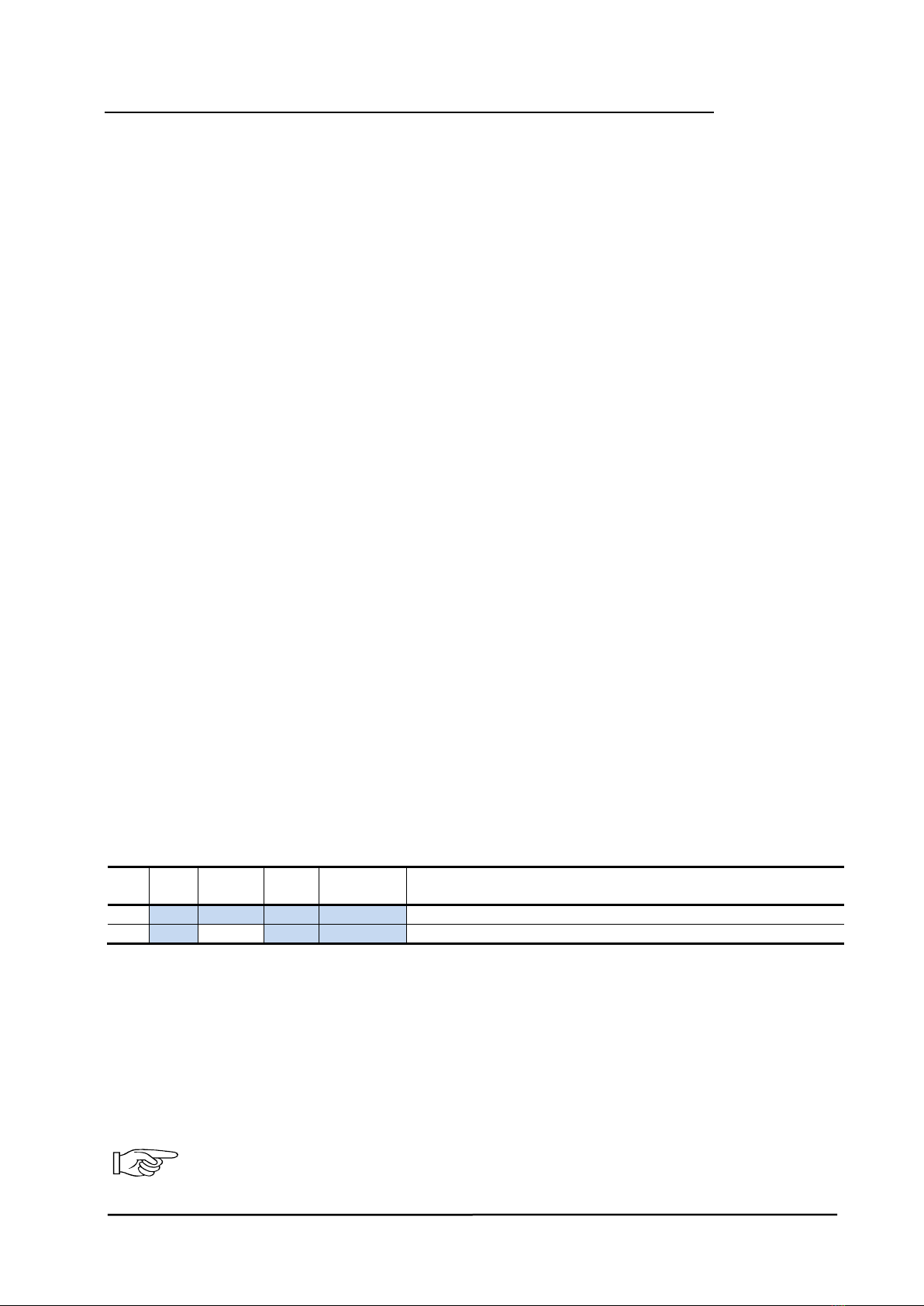
Example: Multi-Sensor Board Cxxx with two SC2 for CO, NO2with basicaddress 09
Input
Mode
Field Bus
Address
Gas
Type
Measuring
Range
Result
1
SC
DP 09
CO
300 ppm
CO SC2 assigned to input 1 und thus field bus address DP09
2
SC
DP 10
NO2
30 ppm
NO2SC2 assigned to input 2 und thus field bus address DP10
Only the parameters with blue background have to be worked on for the Cxxx addressing and the SC registration.
Mode: Not active: = SC assignment to input not possible
SC: = SC assignment possible
Analog: = Input with 4-20 mA signal, assignment possible
Gas type and meas. range: Selection of gas type and measuring range of the SC connected to the
input or of the analog sensor
The registration is only accepted if the assigned gas type/measuring range are identic in the Cxxx and in the
SC. Gas type and measuring range of the Cxxx are checked for identity by the GC Controller, too.
Only one SC per gas type must be connected to the same Multi-Sensor Board.
Two SC2 sensor heads of the same gas group (Freons) must not be connected.
User Manual -
Multi-Sensor Board Cxxx
Page 10
GAMSB_E_0220
5.7 Calibration
New SC2/MC2 Sensor Heads are always delivered factory-calibrated by MSR-E. This is documented by the
calibration label indicating date and calibration gas. A repeated calibration is not necessary during
commissioning if the device is still in its original packaging (air-tight protection by the red protective cap)
and the calibration doesn’t date back more than 12 months for CO2sensors and 3 months for all other gases.
The calibration of the sensor head is done on the display; for versions without display, you need a PC tool or
the STL06 Service Tool. There is an automatic routine in the calibration menu of the Service Tool STL.
As long as the calibration menu is open and the sensor is gassed with test gas, the alarm release is blocked.
Prior to calibration the sensor must be connected continuously to the power supply for stabilization for a
running-in period (see User Manual of Sensor Cartridge).
There is also the possibility to exchange the SC against a calibrated SC on site. The used SC can then be
calibrated directly in the office or at the MSR_E Calibration Service and then reused.
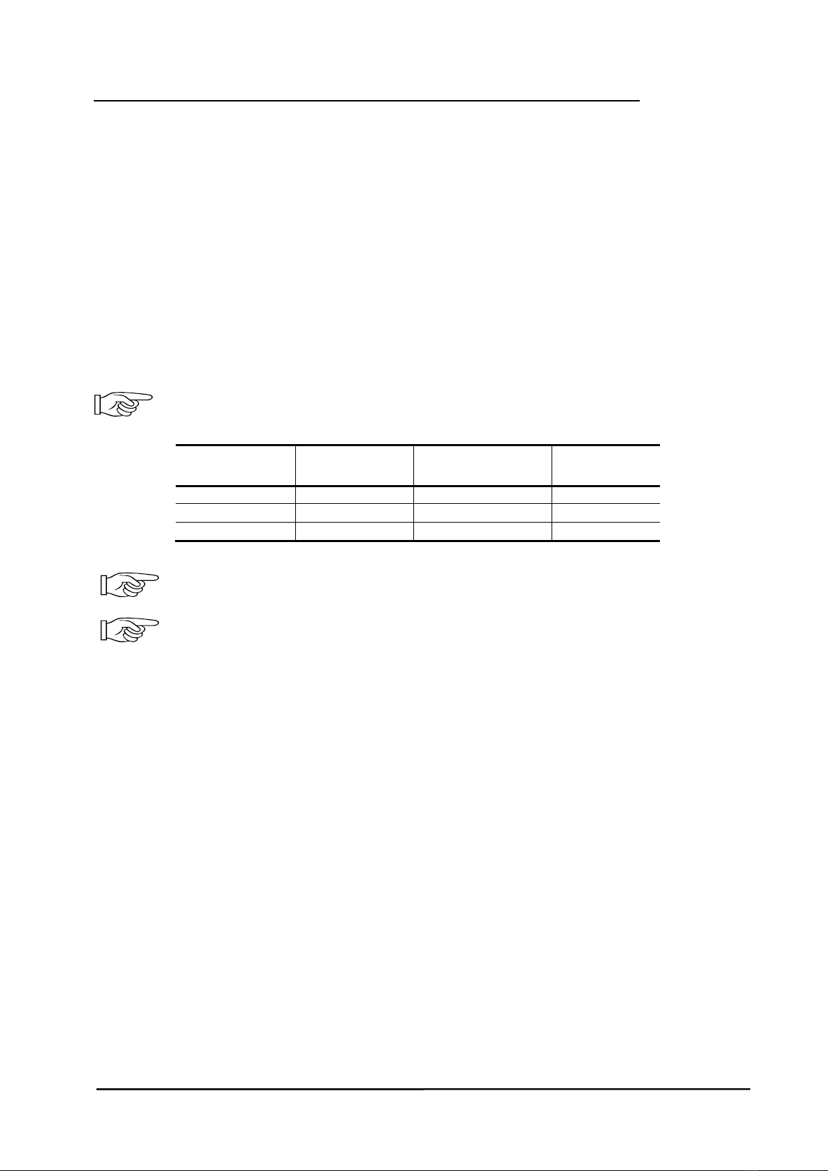
Prior to calibration the Sensor Cartridge must be supplied with power voltage without
interruption for warm-up and stabilisation. The warm-up time depends on the sensor element
and is shown in the following table for Example: See also User Manual for Sensor Cartridge
Sensor Cartridge
Warm-up for
calibration (h)
Stabilization time to
specification (min)
Flow rate
(ml/min)
CO
24
60
150
NO2
24
60
500
LPG (C3H4)
24
60
150
Table Calibration
Please observe proper handling procedures for compressed gas and test gas bottles (regulations
TRGS 220)!
Test gas can be toxic, so never inhale it!
Symptoms: Dizziness, headache and nausea.
Procedure if exposed: Remove victim to fresh air, seek medical attention.
5.8 Calibration with DGC-06 Software PCE06
•Connect DGC-06 Software PCE06 Interface to the Multi-Sensor Board.
Prior to calibration you have to activate the mode “Special Mode” at the MSB, only then the
calibration menu is enabled. During the special mode the Cxxx doesn’t issue alerts.
•Select the Sensor Cartridge to be calibrated by selecting the gas type.
Zero calibration
•The current zero offset and the offset value of the first calibration is read with "Read".
•Slide calibration adapter carefully onto the Sensor Cartridge.
•Apply synthetic air (flow rate according to the table "calibration", 1 bar ± 10%) to the Sensor
Cartridge.
•When the value is stable, the new zero offset factor is calculated with "Calibration".
The new offset factor is checked for plausibility and stored in the buffer memory. The current measured
value is output with the new offset factor and the offset display is updated.
•With "Save" the new offset factor is written in the SC memory, only then the Zero calibration has
been successfully completed. If you exit the menu without pressing "Save", the original offset data
for the measured value calculation will continue to be used.
With a zero reading> 10% of measuring range during the zero calibration, zero calibration is not possible.

User Manual -
Multi-Sensor Board Cxxx
Page 11
GAMSB_E_0220
Gain calibration
•Enter test gas concentration (value between 30 and 70 % of the measuring range)
•The current sensor element sensitivity is read with "Read".
•Slide calibration adapter carefully onto the Sensor Cartridge.
•Apply test gas (flow rate according to the table "calibration", 1 bar ± 10%) to the Sensor Cartridge.
•When the value is stable, the new gain factor is calculated with "Calibration".
The new gain factor is checked for plausibility and stored in the buffer memory. The current measured value
is output with the new gain factor and the sensor element sensibility is updated.
•With "Save" the new gain factor is written in the SC memory, only then the gain calibration has been
successfully completed. If you exit the menu without pressing "Save", the original gain data for the
measured value calculation will continue to be used.
By limiting the gain factor, calibration will not be possible anymore when the sensitivity of the sensor
reaches a residual sensitivity of 40 %. Then the Sensor Cartridge has to be replaced
For more information, see the user manual of the DGC-06 Software PCE06.
5.9 Exchange of Sensor Cartridge SC2
Instead of the on-site calibration, the used SC can be easily and conveniently replaced by a calibrated one.
The communication of the local bus (Sensor Cartridge <> MSB) is continuously monitored
during operation and results in an immediate error message on the gas controller in case of
fault or interruption. When replacing the sensor unit, the communication of the local bus is also
interrupted when unplugging the SC connector which leads to an immediate triggering of the
error message.
•Disconnect the SC2 connector from the Cxxx (error message will be activated).
•Loosen the locknut.
•Remove used SC2.
•Take calibrated SC2 out of the original packaging, check for gas type, measuring range and valid
calibration date.
•Insert the SC2 and retighten with lock nut.
•Insert the SC2 plug into the socket at the Cxxx. Check plug for proper engagement.
The local bus communication is automatically established and tested. At the same time the gas type and the
measuring range of the "new" SC are compared with the data stored in the Cxxx. If they match and the
communication is correct, the error message will be automatically acknowledged at the Gas Controller.
The yellow LED of the Cxxx flashes with a pulse duration of 1 sec., while the SC connector is disconnected
(communication error). After the local bus communication has been re-established and the conformity test
has been successful, the LED will go into flashing mode with 3 sec. pulse duration.
•Perform functional test of the exchanged SC with gas generator. On successful completion of the
test, the flashing LED goes off after approximately 10 sec.
The sensor element is treated with a defined gas concentration with the help of the gas generator. As a result
the measurement signal acknowledges the LED when an internal switching threshold is reached. With this
test, the complete function chain “Sensor Element > Sensor Cartridge> Local Bus> MSB> Field Bus> GC
Controller”is tested.

User Manual -
Multi-Sensor Board Cxxx
Page 12
GAMSB_E_0220
6Inspection and Service
For regular maintenance und calibration of the sensor by trained technicians we recommend concluding a
service contract with MSR-E or one of their authorized partners.
According to EN 45544-4, inspection and service has to be executed at regular intervals. The maximum
intervals have to be determined and observed by the person responsible for the gas warning system
according to the legal requirements. MSR-E recommends applying the inspection and maintenance intervals
as prescribed in the general regulations of the gas measuring technique like VDI-2053, EN 60079-29-1 etc.
The inspection interval normally is three months. The recommended maintenance intervals depend on the
connected Sensor Cartridges. If different intervals are valid, always consider the shortest one.
Inspections and services must be documented. The date for the next maintenance has to be affixed to the
sensor.
6.1 Inspection
Gas sensors should be controlled regularly by a competent person according to EN 45544-4. The following
has to be checked in particular:
•Maintenance / calibration interval not exceeded.
•Visual inspection of the sensor including cable for damage, vandalism etc.
•Remove dust deposits, especially at the gas inlet.
•The filter at the gas inlet has to be replaced if extremely dirty.
•Check the Unit including measuring head for dust, dirt and moisture deposits and clean it with a dry
cloth if necessary.
6.2 Service and Calibration
When performing maintenance, you have to do the calibration and the functional test in addition to the
inspection.
6.3 Trip Test with Reference Gas
By applying the reference gas with a concentration > alarm threshold 2, the set alarm thresholds are
exceeded, and all output functions are activated. It is necessary to check if the connected output functions
are working correctly (e.g. the horn sounds, the fan switches on, devices shut down). By pressing the push-
button on the horn, the horn acknowledgment must be checked. After removal of the reference gas, all
outputs must automatically return to its initial position.
7Project protection
To prevent access to the sensitive calibration data by third parties, every customer receives his own internal
project key. All projects of the customer are delivered with this key. The key is also stored in each STL-06
tool that the respective customer buys.
If the keys do not match, the following message appears
NO ACCESS AUTHORIZATION
The calibration is documented in the User Manual of the Service Tool.

User Manual -
Multi-Sensor Board Cxxx
Page 13
GAMSB_E_0220
8Troubleshooting
8.1 Multi-Sensor Board
Trouble
Cause
Solution
Green LED isn’t on.
Power voltage not applied.
Measure tension at X4:
(16-28 V DC) Pin 1 (+) and 2 (-)
Polarity not correct at X4.
Connect correctly.
Connector X4 not plugged in.
Check the plug.
Wire breakage
Check the wiring.
Green LED doesn’t flash.
Cxxx hasn’t got any address. Check Cxxx address, address
correctly.
Cxxx: no field bus communication
Check field bus wiring,
topology and termination.
No measured value at the Tool or
Controller
SC not or wrongly plugged in.
Check SC plug.
SC not registered.
Register SC.
SC gas type/measuring range doesn’t
match with registered ones.
Check SC data<> registration
data for conformity.
Message at the Tool / Controller:
- 24 V DC voltage <range>
- 5 V DC voltage <range>
- Temp. <range>
- WatchDog triggered.
Internal error
Replace Cxxx.
8.2 Sensor Cartridge (Messages at the Tool / Controller)
Measuring signal <range>
Internal error
Replace SC.
5 V DC voltage < range >
Temp. < range >
WatchDog triggered.
SC Input 1 stored type
Wrong SC type at input 1
Check SC at input 1, replace it.
SC Input 2 stored type
Wrong SC type at input 2
Check SC at input 2, replace it.
SC Input 3 stored type
Wrong SC type at input 3
Check SC at input 3, replace it.

User Manual -
Multi-Sensor Board Cxxx
Page 14
PolyGard®is a registered trademark of MSR Made in Germany GAMSB_E_0220
9Technical Data
9.1 Multi-Sensor Board (Cxxx)
ELECTRICAL
Power supply
16–29 V DC, reverse-polarity protected
Power consumption (24 V DC) only Cxxx
100 mA (2.4 VA)
Analog input
Input signal
4–20 mA, overload and short-circuit proof, input resistance 200
Tension for external analog sensors
24 V DC, max. 100 mA
Digital input
Signal input
Potential-free contact
Function
Acknowledge or test function
Analog output signal**
Proportional, overload and short-circuit proof, load 500 Ohm
4–20 mA = measuring range
2.4–4.0 mA = underrange
> 20–21.2 mA = overrange
2.0 mA = fault
Output for local bus
5 V DC, 250 mA max.,
overload, short-circuit and reverse-polarity protected
Power relays (3)
240 V AC, 5 A, potential-free, change-over contact (SPDT)
SERIAL INTERFACE
Local bus
1-wire / 19200 Baud
Field bus
RS-485 / 19200 Baud
Tool bus
2-wire / 19200 Baud
AMBIENT CONDITIONS
Temperature range
-35 °C to +60 °C (-31 °F to 140 °F)
Humidity range
15–95 % RH not-condensing
Storage temperature
5 °C to 40 °C (41 °F to 104 °F)
Storage time
6 months
PHYSICAL
Protection class (delivery status)*
IP65
Wire connection: Field bus
Local bus
Digital input, analog output
Power supply, relays
Screw-type terminal min. 0.25 mm2, max. 2.5 mm2 (24 to 10 AWG)
3-pin connector
Screw-type terminal min. 0.25 mm2, max. 1.3 mm2 (24 to 16 AWG)
Screw-type terminal min. 0.25 mm2, max. 2.5 mm2 (24 to 10 AWG)
REGULATIONS
Directives
EMC directives 2014/30/EU
Low voltage directive 2014/35/EU
CE
EN 61010-1:2010
Conformity to:
EN 50271
Option:
ANSI/UL 61010-1
CAN/CSA-C22.2 No. 61010-1
Warranty
1 year on sensor (not if poisoned or overloaded)
2 years on device
OPTIONS
DISPLAY
LCD
Two lines, 16 characters each, background highlighted in 2 colours
Operation
Menu driven via six pushbuttons
Power consumption
5 V, 60 mA, 0.3 VA
MODBUS PROTOCOL RTU RS-485
Transmission of current measured values & alarm stages
*If there are changes on the housing it has to be re-evaluated
** For dynamic input impedances of the receiver, a coupling resistance of 560 must be inserted in series
All specifications were collected under optimal test conditions.
We confirm compliance with the minimum requirements of the applicable standard.
User Manual -
Multi-Sensor Board Cxxx
Page 15
GAMSB_E_0220
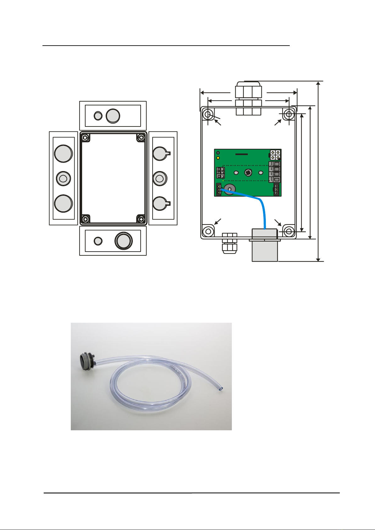
10 Figures
Fig. 1 Fig. 2
Housing A knockouts Housing A dimensions
Fig. 3
Calibration adapter
M20
M20
M25
M20
M12/M20M12/M20
M25
M25 M20
M12M12
X2
X3
X7
X4
94 mm
79 mm
Mounting
Mounting
Mounting
Mounting
115mm
130 mm
180 mm
D = 4 mm

User Manual -
Multi-Sensor Board Cxxx
Page 16
GAMSB_E_0220
11 Part Disposal
Since August 2005 there are EC-wide directives defined in the EC Directive 2002/96/EC and in national
codes concerning the waste electrical and electronic equipment and also regarding this device.
For private households there are special collecting and recycling possibilities. For this device isn’t registered
for the use in private households, it mustn’t be disposed this way. You can send it back to your national sales
organisation for disposal. If there are any questions concerning disposal, please contact your national sales
organisation.
Outside the EC, you have to consider the corresponding directives.
12 Notes and General Information
It is important to read this user manual thoroughly and clearly in order to understand the information and
instructions. The PolyGard®2devices must be used within product specification capabilities. The appropriate
operating and maintenance instructions and recommendations must be followed.
Due to on-going product development, MSR-Electronic GmbH reserves the right to change specifications
without notice. The information contained herein is based upon data considered to be accurate. However, no
guarantee is expressed or implied regarding the accuracy of these data.
12.1 Intended Product Application
The PolyGard®2 devices are designed and manufactured for control applications and air quality compliance
in commercial buildings and manufacturing plants.
12.2 Installers’ Responsibilities
It is the installer’s responsibility to ensure that all PolyGard®2I devices are installed in compliance with all
national and local codes and OSHA requirements. Installation should be implemented only by technicians
familiar with proper installation techniques and with codes, standards and proper safety procedures for
control installations and the latest edition of the National Electrical Code (ANSI/NFPA70).
The equipotential bonding required (also e.g. secondary potential to earth) or grounding measures must be
carried out in accordance with the respective project requirements. It is important to ensure that no ground
loops are formed to avoid unwanted interference in the electronic measuring equipment.
It is also essential to follow strictly all instructions as provided in the user manual.
12.3 Maintenance
It is recommended checking the PolyGard®2 device regularly. Due to regular maintenance any performance
deviations may easily be corrected. Re-calibration and part replacement in the field may be implemented by
a qualified technician and with the appropriate tools. Alternatively, the easily removable plug-in Sensor
Cartridge with the sensor element may be returned for service to MSR-Electronic GmbH.
12.4 Limited Warranty
MSR-Electronic GmbH warrants the PolyGard®2 devices for a period of one (1) year from the date of
shipment against defects in material or workmanship. Should any evidence of defects in material or
workmanship occur during the warranty period, MSR-Electronic GmbH will repair or replace the product at
their own discretion, without charge.
This warranty does not apply to units that have been altered, had attempted repair, or been subject to abuse,
accidental or otherwise. The warranty also does not apply to units in which the sensor element has been
overexposed or gas poisoned. The above warranty is in lieu of all other express warranties, obligations or
liabilities.
This warranty applies only to the PolyGard®2 devices. MSR-Electronic GmbH shall not be liable for any
incidental or consequential damages arising out of or related to the use of the PolyGard®2 devices.
Table of contents


