West Mountain Radio RIGblaster pro User manual

RIGblaster pro
the complete computer interface
for your radio
OWNERS MANUAL
West Mountain Radio
www.westmountainradio.com
18 Sheehan Avenue, Norwalk, CT 06854 tel 203-853-8080 fax 203-299-0232
Rev 8 – Dec 2006

1
PREFACE
Thank you for buying the RIGblaster pro. Whether you are upgrading from another RIGblaster, another
sound card interface, or this is your first interface, we think you will be pleased with the capabilities of
the pro. After building close to 20,000 RIGblaster sound card interfaces we felt we should introduce an
interface that does everything that can possibly be done with a computer and a radio.
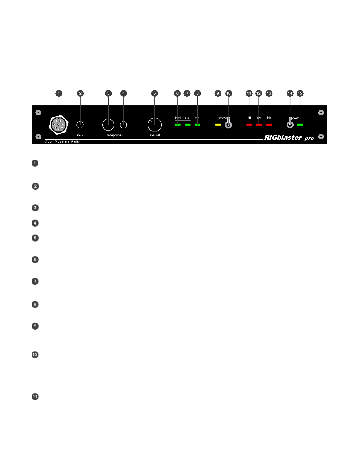
For basic Amateur Radio sound card operation the RIGblaster pro is easier to set up and operate than
any other sound card interface. Front panel status indicators show at a glance, signal routing, audio
signal level and activation of PTT, CW and FSK control and keying.
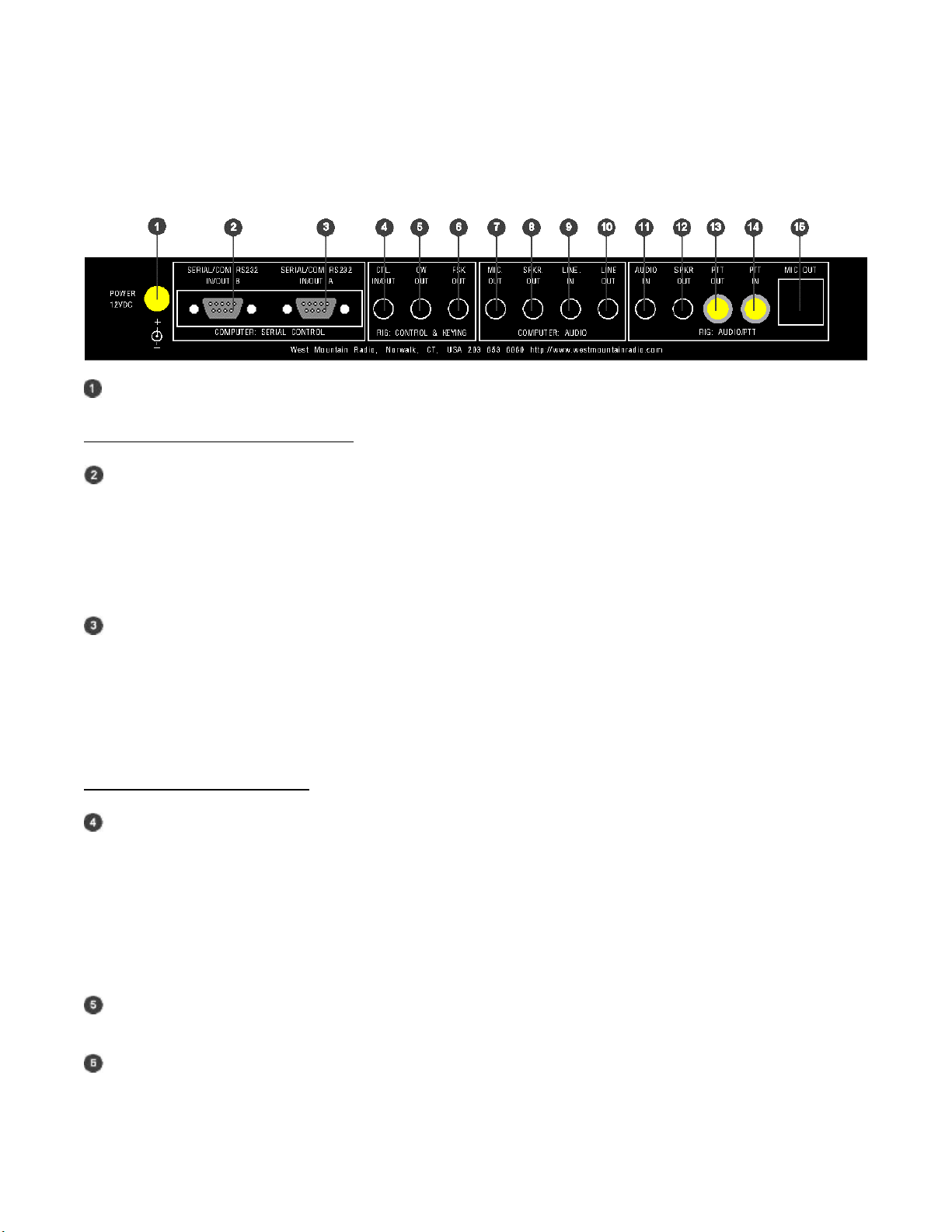
The cable hookups are as simple as all other model RIGblasters for the same function. The RIGblaster
pro does, however, offer many more possibilities, for instance, four ways to connect your receive audio.
Understandably, there are many additional connection and configuration options to provide the full
functionality.
To do whatever you would like that is possible with a RIGblaster pro choose the optional connections
described in this manual. Feel free to try all the possible functions one at a time or all at once depending
on your desire to experiment. In the spirit of Amateur Radio, that is what it is all about!
The RIGblaster pro was conceived as a platform to support all Amateur Radio sound card, keying and
rig control software, even software that has not yet been written.
CHOOSING A MOUNTING LOCATION
The supplied microphone cable is 3 feet long and the computer cables are 6 feet long. Choose a location
that allows these cables to reach your radio and your computer. You may extend the computer cables
within reason. You should have the computer at your operating position with the radios. Do not attempt
to run the RIGblaster pro with a computer across the room, especially if it is on a different house wiring
circuit than your ham station.
Put it where you can see and operate it easily and where you will have access to the back panel.
The top cover can be removed without disconnecting the cables for easy access to the internal jumpers.
If you will be using a hand microphone with a coiled cord, consider the tug on the cord. The RIGblaster
pro is fairly heavy but could be pulled around with a coiled mic cord. You can use the supplied double
stick pads as an easy way to secure it.
Locate the RIGblaster pro at least 18 inches away from anything that can have a strong magnetic field,
such as transformer type power supplies, amplifiers, CRT type monitors or rotor control boxes. Do not
put the RIGblaster pro in strong RF fields.
The RIGblaster pro requires little or no ventilation and can be put anywhere that does not block the
ventilation for another piece of equipment that does require ventilation.

2
TABLE OF CONTENTS
PREFACE .............................................................................................................................................. 1
UNPACKING......................................................................................................................................... 3
PLEASE NOTE:................................................................................................................................... 4
PANEL DESCRIPTION .................................................................................................................... 5
FRONT PANEL....................................................................................................................................... 5
REAR PANEL ......................................................................................................................................... 7
INSTALLATION & CONNECTIONS ........................................................................................... 9
STEP 1 - INSTALL SOFTWARE AND START RECEIVING ........................................................ 9
STEP 2 - INSTALL JUMPERS and CONNECT MIC CABLE ..................................................... 10
STEP 3 - CONNECT SERIAL CABLE(s) ....................................................................................... 10
STEP 4 - CONNECT AUDIO CABLES........................................................................................... 11
STEP 5 - SET AUDIO LEVELS ....................................................................................................... 13
STEP 6 - CW CABLING AND SETUP............................................................................................ 14
STEP 7 - FSK CABLING AND SETUP........................................................................................... 15
STEP 8 - RIG CONTROL CABLING AND SETUP....................................................................... 15
STEP 9 - ADVANCED AUDIO PROCESSING CONSIDERATIONS ........................................ 18
STATION HOOKUP DIAGRAM (basic sound card function)....................................... 19
STATION HOOKUP DIAGRAM (all features & functions).............................................. 21
MICROPHONE JUMPER DIAGRAMS.................................................................................... 24
8 PIN SCREW ON MICROPHONE JUMPERING ........................................................................ 24
RJ45 MODULAR STYLE MICROPHONE JUMPERING............................................................. 26
RECEIVE AUDIO AVAILABLE ON THE MIC CONNECTOR..................................................... 27
MIC MODE JUMPER – P6 ............................................................................................................... 28
COM PORT & RIG CONTROL JUMPER DIAGRAMS (P16)........................................ 29
PTT LOOP JUMPER – P5................................................................................................................ 31
RECEIVE AUDIO CONNECTION OPTIONS....................................................................... 32
TROUBLESHOOTING TIPS........................................................................................................ 34
INDEX .................................................................................................................................................... 35

3
UNPACKING
Items included with the RIGblaster pro
1 Power Supply Isolated 12VDC
1 CD-ROM WMR Collection of Third Party Software
1 Microphone Cable (RJ45 to 8 pin screw on)
1 DB9M to DB9F Serial Cable
1 USB Interface Cable
6 1/8 inch (3.5mm) Stereo Mini Plug 6’ Patch Cords
1 Owners Manual (not pictured)
1 Patch Cord Label Set
1 Accessories Kit (that contains)
11 White Wire Jumpers
6 Blue Shunt Jumpers
1 Adapter – 1/8 inch (3.5mm) Mini (female) to ¼ inch Plug
4 3M Adhesive Pads (not pictured)

4
PLEASE NOTE:
In this manual we will refer to the sound device on a computer as “Sound Card”. We understand many
computer sound devices are integrated onto the motherboard of the computer. We will stick to the more
familiar wording “Sound Card”.
The words “Radio”, “Transceiver” and “Rig” as used within this document are synonymous. Also
“c.s.” as used throughout this document means audio generated by the sound card, or Computer Sound.

5
PANEL DESCRIPTION
FRONT PANEL
- MICROPHONE CONNECTOR, 8-Pin Screw-on Microphone Connector – connects your radio microphone to
the RIGblaster pro. (May be used as mic out on a radio with an RJ45 microphone connector)
- “mic 2”, an auxiliary mic connector for connecting a microphone with a 1/8 inch (3.5mm) connector. Main mic
does not need to be disconnected as this jack switches over automatically.
- COMPUTER MONITOR HEADPHONE JACK – Accepts Headphones with a ¼ inch Jack
- COMPUTER MONITOR HEADPHONE JACK – Accepts Headphones with a 1/8 inch (3.5mm) Jack
- “level set” – For adjusting the audio level being fed from the computer audio Line Out or headphone out to
the Mic input of the attached radio in order to set transmit drive level.
- “level” LED – A Green LED that indicates the presence of sound card audio in Receive Mode. In Transmit
mode, it indicates sufficient sound card audio to adequately modulate most radios.
- “c.s.” LED – A Green LED, when on, indicates computer sound (c.s.) is being fed to the radio. When this LED
is on, the direct microphone path to the radio is disconnected.
- “mic.” LED – A Green LED, when on, indicates the microphone is available to the radio. See STEP 9
ADVANCED AUDIO PROCESSING CONSIDERATIONS later in this manual for more information.
- “process” LED – A Yellow LED indicating that the RIGblaster pro is in Process Mode This LED will turn on
only when the “process Switch” is on and PTT is pressed on the attached mic or via an attached PTT switch/foot
switch or when PTT is activated by software through the serial port connection from the computer.
- “process” Switch – Turns process mode on or off. Up is ON and down is OFF. This switch must be OFF
when the RIGblaster pro is turned off for your mic to work normally. If the “process Switch” is OFF, microphone
audio is fed directly to the radio. When the “process Switch” is ON mic audio can be connected via the
RIGblaster pro to the computers mic input and back into the radio. Please see STEP 9 ADVANCED AUDIO
PROCESSING CONSIDERATIONS later in this manual for more information about Process Mode.
- “ptt” LED – This Red LED indicates when PTT is activated by your mic, foot switch or by software through the
serial port connection from the computer.

6
PANEL DESCRIPTION continued
FRONT PANEL continued
- “cw” LED – This Red LED indicates when CW keying is active with appropriate software for CW keying. This
LED may be on with the RIGblaster pro turned off if the serial port to the computer is connected and the DTR line
of that serial port is active.
- “fsk” LED – This Red LED blinks when FSK keying is active with appropriate software for FSK keying. Under
certain conditions, this LED may be on without an active FSK program running in the computer if the serial port to
the computer is connected and the TXD line of that serial port is in an up state. This condition can also occur with
some USB to serial port converters.
- “power” SWITCH – Turns power ON and OFF. Up is ON and down is OFF.
- “power” LED – a Green LED indicating the RIGblaster pro is turned on.

7
PANEL DESCRIPTION continued
REAR PANEL
- POWER INPUT – 12 VDC Input – connects the Supplied Power Supply to the RIGblaster pro.
COMPUTER: SERIAL CONTROL
- SERIAL/COM RS232 IN/OUT B– DB9 - For connection to a second available computer serial port or USB
Interface Cable. This is the secondary jack and depending on the software you wish to run, this may be used for
ONLY ONE of the following functions:
FSK keying (if SERIAL/COM RS232 IN/OUT A is being used for Rig Control)
Rig Control (if SERIAL/COM RS232 IN/OUT A is being used for FSK)
Rig Control pass through from SERIAL/COM RS232 IN/OUT A (only if your radio has a DB9 Rig Control
jack)
- SERIAL/COM RS232 IN/OUT A– DB9 - For connection to an available computer serial port or USB Interface
Cable. This is the primary jack and depending on the software you wish to run, this may be used for ONLY ONE
of the following combination of functions:
PTT Control, CW Keying and Rig Control
PTT Control, CW Keying and FSK Keying
See COM PORT & RIG CONTROL JUMPER DIAGRAMS later in this manual.
RIG: CONTROL & KEYING
- CTL. IN/OUT – 1/8 MINI JACK - for connection to ICOM or TenTec radios with a CI-V REMOTE CONTROL
JACK for controlling ICOM or TenTec radios with appropriate Rig Control software. This jack is also used to
connect to Yaesu radios that have DIN jack TTL CAT capability for controlling Yaesu radios with appropriate Rig
Control software. Specific jumpering on the P16 jumper block inside the RIGblaster pro is required for ICOM,
TenTec or Yaesu radios. When jumpered for ICOM radios, both transmitted and received data are on the tip in
relation to the sleeve and there is no connection to the ring. When jumpered for Yaesu, received data from the
radio is on the tip and transmitted data to the radio is on the ring, both are in relation to ground on the sleeve. See
COM PORT & RIG CONTROL JUMPER DIAGRAMS later in this manual for additional information about Rig
Control.
- CW OUT – 1/8 MINI JACK - for connection to the CW straight key jack on your radio for computer CW keying
with appropriate software. Compatible with solid state radios that key with positive pull down.
- FSK OUT – 1/8 MINI JACK - for connection to the FSK input of your radio for computer FSK keying with
appropriate software. Compatible with solid state radios that key with positive pull down.

8
PANEL DESCRIPTION continued
REAR PANEL continued
COMPUTER: AUDIO
- MIC. OUT – 1/8 MINI JACK - for connection to Mic In on your Desktop computer. (May not apply to LapTop
Computers where Mic In is used for Receive Audio input to the computer soundcard) This provides the path for
connecting your radio microphone to your computer sound Mic In. This output must be activated with the jumper
on the P6 jumper block. See the section titled MIC MODE JUMPER – P6 later in this manual.
- SPKR OUT – 1/8 MINI JACK - Plug your computer speakers into this jack.
- LINE IN – 1/8 MINI JACK - for connection to the computer sound Line Out. (Speaker Out for un-amplified
computer speakers, headphone out for a LapTop)
- LINE OUT – 1/8 MINI JACK – for connection to the computer sound Line In. (Mic In on LapTops)
RIG: AUDIO/PTT
- AUDIO IN – 1/8 MINI JACK – for connection to either fixed or variable line or speaker level audio from your
radio. Not used if receive audio is taken directly from the P1 jumper block. See the section titled RECEIVE
AUDIO AVAILABLE ON THE MICROPHONE CONNECTOR later in this manual.
- SPKR OUT – 1/8 MINI JACK – for connection of your radio external speaker. Used in cases where the radio
external speaker output is used to supply audio to the computer sound Line In. If you use fixed or line level audio
from your radio to AUDIO IN, no. 11 above, this jack will not be used.
- PTT OUT – RCA PHONO JACK – for connection of your external PTT switch or PTT foot switch. This jack,
as well as the PTT IN jack, may be separated and used for connection to an external sequencer. See the section
titled PTT LOOP JUMPER - P5 later in this manual.
- PTT IN – RCA PHONO JACK – for connection of your external PTT switch or PTT foot switch. This jack, as
well as the PTT OUT jack, may be separated and used for connection to an external sequencer. See the section
titled PTT LOOP JUMPER - P5 later in this manual.
- MIC OUT – RJ45 MODULAR JACK – for connection to the Microphone connector on your radio. This
connection is made using the included Mic Cable. (May be used as mic in for a radio with an RJ45 microphone
connector.)
Note: References used throughout this document, such as (R15) refer to the RIGblaster pro Switch,
Connector, Knob, Jack or LED as illustrated on these PANEL DESCRIPTION pages.
Example; “This connection is made to the MICROPHONE OUTPUT (R15) on the RIGblaster pro”.
(R15) refers to Rear Panel illustration number so you can quickly locate this particular Switch,
Connector, Knob, Jack or LED.

9
INSTALLATION & CONNECTIONS
STEP 1 - INSTALL SOFTWARE AND START RECEIVING
You do not need the RIGblaster pro to receive so leave it in the box!
Insert our CD in your CD ROM drive. The West Mountain Radio screen will pop up in a few seconds.
From our screen click the “XMIT” button for the “West Mountain Radio RIGblaster Software
Collection”.
Click the “XMIT” button for whatever mode you would like to try.
Click “XMIT” for whatever program you would like to try. Follow the installation prompts that appear
on the screen to install the software.
Close the West Mountain Radio Window and put the West Mountain Radio CD in a safe place.
Your program is now installed. From Windows, click, “Start”, “Programs”, find your program icon and
click to start that program.
Using one of the supplied mini plug cables, (referred to throughout this manual as “Patch Cord”)
connect the speaker output of your radio to the Line In (Mic In on a laptop) of your computer.
There are three other receive audio connection options that will be described later in this manual.
Tune in an appropriate signal for the mode you have selected. On our CD you will find a chart of
standard operating frequencies for the various modes. So you can get a better understanding of what to
listen for when tuning, our CD also contains recordings of many of these exciting new modes.
Double click the little yellow speaker icon in the lower right corner of your Windows screen. You will
get your Windows sound playback control panel. Click “Options”, “Properties”, “Recording” and “OK”
to get the recording control panel. With your mouse, turn up the “Line In” slider (or “Microphone In”
on a laptop) about half way and “Select” that input.
Turn up your radio volume control (AF Gain) to the 9 or 10 o’clock position or until you see a signal
displayed on the ham radio sound card software screen.
Follow the instructions or help that comes with the software to tune in the station using your radio
and/or the software.
You should then be receiving that station. Try tuning in several other stations or even try another
program or mode.
Before proceeding beyond this step, you should disconnect the audio cable installed above.

10
STEP 2 - INSTALL JUMPERS and CONNECT MIC CABLE
Jumpers are not installed as shipped; they are packed separately (see Items included with the RIGblaster
pro on Page 3). The cover must be removed to install jumpers, see MICROPHONE JUMPERING and
SERIAL PORT & RIG CONTROL JUMPER DIAGRAMS in the back of this manual. These jumpers
are necessary so the RIGblaster pro microphone pin assignments will match the different microphone
pin assignments of various radio equipment manufacturers such as Icom, Yaesu, Kenwood, Alinco,
TenTec, Elecraft, etc..
After you have installed the jumpers for your specific radio, connect the supplied Mic Cable in one of
the following manners:
FOR RADIOS WITH A STANDARD 8 PIN SCREW ON MICROPHONE CONNECTOR
Using the supplied 3 foot mic cable connect the end with the RJ45 connector to MIC OUT (R15)
on the rear of the RIGblaster pro. Connect the other end to the Mic Connector on your radio.
Then plug your radio microphone into MICROPHONE CONNECTOR (F1) on the front panel of
the RIGblaster pro.
FOR RADIOS WITH AN RJ45 MICROPHONE CONNECTOR
Using the supplied 3 foot mic cable connect the end with the RJ45 connector to Mic Connector
on your radio. Connect the other end to the to MICROPHONE CONNECTOR (F1) on the front
panel of the RIGblaster pro. Then plug your radio microphone into MIC OUT (R15) on the rear
of the RIGblaster pro.
Make sure the RIGblaster pro Power Switch (F14) is turned off, then plug the wire from the Power
Supply into the Power Jack (R1) on the rear panel of the RIGblaster pro. Plug in the Power Supply, turn
off the RIGblaster pro Process Switch (F10) then turn on the RIGblaster pro Power Switch (F14). The
Green “Power” LED (F15) and the Green “mic” LED (F8) should come on. The Green “level.” LED
(F6) will come on briefly then will go off.
Confirm that EVERYTHING on your mic works correctly, including an on-the-air audio report. If your
mic works perfectly, you have the jumpers installed correctly. If you have a problem, make sure you
used the jumper diagram that matches your mic, not necessarily your radio. After market mics,
especially Yaesu may not have exactly the same wiring as your original radio mic.
At this point, if and only if your mic works perfectly, continue to the next step.
STEP 3 - CONNECT SERIAL CABLE(s)
We suggest you read this step through entirely before doing it.
Turn off the RIGblaster pro Power Switch. The Green “Power” LED and the Green “mic” LED should
go off.
Turn off your radio and your computer before connecting cables to either.

11
If your computer does not have a real Serial Port, you will be using the included USB Interface Cable.
To install the drivers necessary to use the USB Interface Cable, please see the “RIGblaster USB Owners
Manual Addendum” on the included CDROM.
One DB9 Male to DB9 Female Serial Cable is supplied with the RIGblaster pro. The specific software
and the manner in which you intend to operate the various functions facilitated by the RIGblaster pro
will determine how you connect the serial cables.
To do basic SoundCard applications such as PSK31, SSTV, CW, RTTY, connect the supplied serial
cable between an available serial port on your computer and SERIAL/COM RS232 IN/OUT A (R3) on
the rear of the RIGblaster pro.
Read the section titled COM PORT & RIG CONTROL JUMPER DIAGRAMS to help you determine if
you need to connect a second serial cable (not supplied) between a second serial port on your computer
and SERIAL/COM RS232 IN/OUT B (R2) on the rear of the RIGblaster pro.
Additional DB9 to DB9 Serial Cables can be purchased from West Mountain Radio at
www.westmountainradio.com.
Turn on the RIGblaster pro Power Switch. The Green “Power” LED and the Green “mic” LED should
come on. The Green “level.” LED (F6) will come on briefly then will go off. At this time no other LED
should light.
Boot the computer. During the boot process you should see the PTT LED (F11) blink on and off at least
once. The CW LED may also come on and go off during the boot. When the boot is complete the PTT
and CW LEDs should be off if not you have a software problem, see the Support pages of our Web Site.
This test may or may not work if you are using the USB Interface Cable in place of a real serial port.
This test confirms that the cable, the computer serial port, and the PTT circuitry in the RIGblaster pro
are working properly together. Also see our web site support page if you have Windows/ME.
www.westmountainradio.com
Do NOT proceed to the next step of the installation if this step FAILS. Except when using USB
Interface Cable.
STEP 4 - CONNECT AUDIO CABLES
We suggest you read this step through entirely before performing it. This will give you a better
understanding of what steps need to be done and what can be skipped.
Turn off the RIGblaster pro Power Switch. The Green “Power” LED and the Green “mic” LED should
go off.
Turn off your radio and your computer before connecting cables to either unit.
Six 1/8 inch Stereo Mini Plug Patch Cords are supplied with the RIGblaster pro. Throughout this step
these will be referred to as “Patch Cords”. What software and the manner in which you intend to
operate the various functions facilitated by the RIGblaster pro will determine how many and where you

12
connect these patch cords. Additional 1/8 inch Stereo Mini Plug Patch Cords can be purchased from
West Mountain Radio www.westmountainradio.com .
We highly recommend that you attach Patch Cord Labels to each end of the Patch Cords before
installing them.
ROUTING: TRANSMIT COMPUTER AUDIO ÆRIGblaster pro ÆComputer Speakers
For Desktop Computers, unplug the computer speakers from the computer and plug them into SPKR
OUT (R8) on the rear of the RIGblaster pro. Then plug one end of a patch cord to the jack on the
computer where the computer speakers were plugged. Plug the other end of that patch cord to LINE IN
(R9) on the rear of the RIGblaster pro.
For laptop computers with only two audio jacks, plug one end of a patch cord to the headphone jack on
the laptop computer and plug the other end of that patch cord to LINE IN (R9) on the rear of the
RIGblaster pro.
ROUTING: RECEIVE RADIO AUDIO ÆRIGblaster pro ÆComputer Sound, Line In
Three methods are available for getting audio from your radio to your computer. The method you use
depends primarily on the options available on your radio. If your radio has the provision for connecting
an external speaker but no other means of getting audio out of the radio, then Method 1 should be used.
If your radio has fixed level audio available from the rear panel via an accessory socket, then Method 2
is recommended. If your radio has output audio available at the mic connector, RIGblaster pro has the
capability to use this as a source for audio input to the computer and this will be Method 3. In all three
methods, RIGblaster pro will provide DC isolation for receive audio between the radio and the
computer.
Method 1:
For this method, you will need an external speaker for your radio.
Plug one end of a patch cord to the External Speaker Output jack of your radio and the other end to
AUDIO IN (R11) on the rear panel of the RIGblaster pro. Then plug your radio external speaker into
SPKR OUT (R12) on the rear panel of the RIGblaster pro.
Plug one end of a patch cord to LINE OUT (R10) on the rear panel of the RIGblaster pro and plug the
other end to Line In on your computer sound.
Method 2:
For this step you will need a special cable. One end of this cable will have a mini plug which is the
same as those provided on the ends of the patch cords supplied with your RIGblaster pro. The other end
will be a connector that will plug into the source of fixed level audio on your radio. This may be labeled
“Data Out, Monitor Out, Record Out, Patch Out, etc. and it could be a din plug, a mini din plug, an RCA
plug, etc. Consult your radio Owners Manual for the required connector. West Mountain Radio has
several cables available for this purpose as RIGblaster optional Accessories for Icom, Kenwood and
Yaesu radios. See www.westmountainradio.com.

13
Plug the mini plug end of this cable to AUDIO IN (R11) on the rear panel of the RIGblaster pro. Plug
the other end of this cable to the connector on your radio that provides fixed level audio as outlined in
the previous paragraph.
Plug one end of a patch cord to LINE OUT (R10) on the rear panel of the RIGblaster pro and plug the
other end to Line In on your computer sound.
Using this method, Method 2, there will be no connection to SPKR OUT (R12) on the rear of the
RIGblaster pro.
Method 3:
Using this method audio is supplied to the RIGblaster pro through the Mic Cable previously installed in
Step 1 above. On some radios output audio is available on a radio mic connector pin and therefore can
be obtained with jumpering on the P1 jumper block inside the RIGblaster pro. See the example under
“MICROPHONE PIN ASSIGNMENTS (example)” later in this manual. Consult the microphone pin
assignment diagram in the Owners manual of your radio to determine which pin on the mic connector
and thus which pin on the P1 jumper block to jumper to RCV AUD and RCV AUD GND.
In the Microphone Pin Assignments example later in this manual, an IC-756PRO, is shown. On the IC-
756PRO, pin 8 is used for receive audio and thus Pin 8 is jumpered to RCV AUD on the OUTPUT side
of the P1 jumper block to provide receive audio to the RIGblaster pro Ground reference must also be
provided by jumpering RCV AUD GND on the INPUT side to GNDTIE on the INPUT side also on the
P1 jumper block. On Icom radios this audio is not fixed, it is variable with the AF Gain control.
After completing the necessary jumpering on the P1 jumper block, plug one end of a patch cord to LINE
OUT (R10) on the rear panel of the RIGblaster pro and plug the other end to Line In on your computer
sound.
STEP 5 - SET AUDIO LEVELS
For the first part of this procedure leave your Radio turned OFF.
Open your Windows sound control panel (double click on the little yellow speaker icon in the task bar)
and un-mute the “wave” output and the left hand “Volume Control” output. Set the virtual “Volume”
and “Wave” sliders to a position one notch down from the top. Also set the virtual balance sliders to the
center.
If your computer speakers are hooked up and they have a volume control knob, turn that knob most of
the way, but not all the way, down. If they do not have a volume knob, they may be too loud and you
will want to turn them off after you are sure that you can turn your sound card up high enough for them
to be uncomfortably loud.
Make sure the RIGblaster pro is turned ON, the “process” Switch (F10) is off and the “level set” Knob
(F5) is all the way Counterclockwise. Set your software to Transmit or Tune. The RIGblaster pro “c.s.”
LED (F7) and “ptt” LED (F11) should be on. If you are using software, such as WinPSK, that brings up

14
both RTS and DTR when set to transmit the CW LED (F12) may also come on. If these LEDs do not
come on, recheck the serial port software setting for PTT control. In the RIGblaster pro, PTT is always
controlled with the RTS. If the “c.s” and “ptt” LEDs are on, then the “level” LED (F6) should also be
ON indicating there is sufficient audio from the sound output of your computer being delivered to the
RIGblaster pro to adequately modulate your radio. At this point, you can refine the wave output setting
on the Windows sound control panel to the point just past where the “level” LED has just come on. Set
the software back to Receive.
Turn ON your Radio for the remainder of this procedure.
For SSB Radios use your normal mic gain setting, turn your speech compressor off and set the
transmitter RF drive (power control) all the way up. You will want to use a dummy load for this
procedure. If you are using PSK software make sure that the transmit audio is between 500Hz and 2500
Hz, otherwise you may be outside the limits of the response of your radio and you may not be able to
transmit properly. Set your software to Transmit or Tune. Then slowly turn up the “level set” Knob
(F5) on the front of the RIGblaster pro to the point where your ALC just starts to move or you have
achieved your normal RF power output.
Your final setting must produce less than full RF power output from your radio.
Warning: you should not exceed the AM, FM or RTTY power rating of your radio. After this setting is
completed, check to make sure your ALC meter is below limiting. Even if your radio is rated at full
output and continuous duty, do not set the audio to full output!
Note that if you run your computer sound output at maximum or close to maximum, and the RIGblaster
pro “level set” turned way down, you may have distortion from your computer sound and a poor quality
signal. Generally the wav and volume sliders should be between 1/3 and 2/3 open and the RIGblaster
pro “level set” Knob should be between 1/8 and 7/8 open.
With an FM rig you must set the audio level with the “level set” Knob using a deviation meter or by
comparing the level of your transmit audio to other stations using another radio.
For a more information about Computer Sound Cards, see the article titled “The In’s and Out’s of a
Sound Card” in October 2003 QST. Also available in PDF format on our Web Site at:
http://www.westmountainradio.com/pdf/Ins&Outs.pdf.
STEP 6 - CW CABLING AND SETUP
Turn off both your radio and the RIGblaster pro before connecting cables to either unit.
Plug one end of a patch cord to the CW OUT (R5) jack on the rear panel of the RIGblaster pro. Plug the
other end into the CW Key jack on your radio. If the CW Key jack on your radio is a ¼” jack, it will be
necessary to use the supplied 1/8” to ¼” adapter.
For computer CW it is necessary to make sure your radio CW keying is set for “Straight Key” mode for
the jack you are using. The remaining setup for computer controlled CW will be done in the application
software you choose. Control of CW is not selectable and will always be done through Serial/Com
RS232 In/Out A, with the DTR line. Make sure when you configure your software that you observe this
convention.

15
On the CW OUT (R5) jack, the sleeve goes to common ground and the tip goes to the keying circuit, the
ring of this connector is not used.
STEP 7 - FSK CABLING AND SETUP
Turn off both your radio and the RIGblaster pro before connecting cables to either unit.
Your radio will have to be capable of FSK / RTTY to utilize this option. FSK wiring is unique to each
Amateur Radio transceiver manufacturer. Therefore you will have to consult your specific radio
Owners Manual for information as to how to connect to the FSK input of your radio.
For many radios, the FSK connection is via an accessory connection on the rear panel of the transceiver.
West Mountain Radio has a readymade cable for connection between a RIGblaster and the FSK input of
many Icom, Kenwood and Yaesu radios. They are available on our web site
http://www.westmountainradio.com under RIGblaster Accessories.
After you have constructed or purchased the correct FSK cable, connect the mini plug end to FSK OUT
(R6) on the rear panel of the RIGblaster pro. Connect the other end of this cable to the appropriate
connection on your transceiver. Always check the wiring prior to connecting homemade cables to your
equipment.
On the FSK OUT (R6) jack, the sleeve goes to common ground and the tip goes to the FSK keying
circuit, the ring of this connector is not used.
Make any necessary jumpering on the P16 jumper block as described later in this manual under COM
PORT & RIG CONTROL JUMPER DIAGRAMS.
In most cases you will have to operate your radio in RTTY mode to enable FSK input.
STEP 8 - RIG CONTROL CABLING AND SETUP
RIG Control cabling and jumpering differs depending on the radio manufacturer.
Most ICOM and TenTec (with CI-V) use a single bi-directional conductor and thus require one of our
standard patch cords to connect the RIGblaster pro and the radio. To cable an ICOM or TenTec (with
CI-V) radio to a RIGblaster pro, connect one end of a patch cord to CTL IN/OUT (R4) on the rear of
the RIGblaster pro. Connect the other end to the “CI-V REMOTE CONTROL JACK” on the rear of
your ICOM or TenTec radio. The factory setting of jumpering on the P16 Jumper Block is already set
for ICOM/TenTec Rig Control through SERIAL/COM RS232 IN/OUT A.
Specific jumpering on the P16 jumper block inside the RIGblaster pro is required for ICOM, TenTec, or
Yaesu radios. When jumpered for ICOM radios, both transmitted and received data are on the tip in
relation to the sleeve and there is no connection to the ring. When jumpered for Yaesu, received data
from the radio is on the tip and transmitted data to the radio is on the ring, both are in relation to ground
on the sleeve. See COM PORT & RIG CONTROL JUMPER DIAGRAMS later in this manual for
additional information about Rig Control.

16
With a Yaesu it is a little more complicated. The Yaesu CAT system uses three wires and they have
different connectors and pin wiring arrangements between different models. Older Yaesu radios require
the rig control TTL (5 volt) to RS232 level converter built into the RIGblaster pro.
For an older Yaesu CAT system you must set the RIGblaster pro rig control jumper P16 to Yaesu. You
must also change the plug on one end of a patch cord to match the Yaesu DIN jack. You must make sure
that the tip of our plug comes from the data out of your radio and the Ring goes to the data in to your
radio. West Mountain Radio has two CAT Cables available for Yaesu radios.
Older Kenwood radios that have provisions for TTL control are not possible to control with a
RIGblaster pro. These Kenwood radios utilize what is referred to as Negative TTL Logic and are not
compatible with the Positive Logic employed in the RIGblaster pro TTL to RS232 converter. Positive
logic, as employed in most computer interface circuitry, represents a logical one with a positive voltage
and a logical zero with a zero voltage.
To connect a RIGblaster pro to Yaesu radios with a 6 pin DIN receptacle with TTL level CAT control,
the following cable would have to be constructed. We have found pin numbers vary from Yaesu model
to model but GND is usually numbered pin 1.
If you have a Yaesu or other brand of radio with an RS232 Rig/CAT control jack you should not use our
rig control output. You may use the RIGblaster pro's RXD & TXD on A passed through to B option (#9
on the P16 Jumper block). This will allow both sound card operation, PTT, CW and rig control with a
single serial port with software such as HamScope, MixW or WriteLog. If you wish to use separate
sound card and rig control programs at the same time you will have to make a direct connection from
your computer to the radio's RS232 control jack. If the radio is equipped with a FEMALE DB-9 RS232
connector for Computer Control (CAT), the following cable will be necessary from the B Port on the
RIGblaster pro to the radio RS232 DB-9. Both DB-9 connectors shown here are MALE connectors.
If you have a newer Kenwood (Example TS-570/870/2000) radio or an Icom IC-7800 with a MALE
RS232 CAT/Rig Control jack you should not use the CTL IN/OUT jack on the RIGblaster pro. You
may use the RIGblaster pro for both sound card operation, PTT, CW and FSK To do CAT on these

17
radios you should use our Optional DB9M to DB9F Serial/Extension Cable or equivalent connected
directly to an available serial port on your computer or to a USB jack on your computer with a USB
Interface Cable or equivalent USB to Serial Port Adapter. For some radios it may be necessary to
connect pins 7 and 8 on the receiver end as illustrated above. This is necessary to fool the radio into
thinking it sees Clear To Send (CTS) in response to it raising Request To Send (RTS). These lines are
not passed through the RIGblaster as they are used for other functions within the RIGblaster.
Please Note: not all programs will do rig control on the same serial port that does PTT and CW.

18
STEP 9 - ADVANCED AUDIO PROCESSING CONSIDERATIONS
A unique feature of the RIGblaster pro is that you may process, equalize, compress or expand
transmitted audio. This is done simply by routing your microphone audio into your computer and back
out to your radio while processing the audio (real time) with appropriate sound card software.
To enable this feature and the ability to make digital recordings of your station operation, you must plug
the jumper on the P6 Jumper Block to send your microphone audio to the computer. See the section
labeled “MIC MODE JUMPER – P6” later in this manual for jumpering diagrams. You must also
connect a cable from the RIGblaster pro MIC OUT (R7) to your Computer Sound Card MIC IN to
enable this feature.
Your computer must have an available Mic In and you must have a full duplex sound card that will pass
the sound card microphone input through software and then back out to the RIGblaster pro.
To enable microphone audio processing you must turn on the “process” switch (F10). The function of
process mode is to redirect audio from your radio microphone through the computer and back to the
radio.
To utilize Process Mode of the RIGblaster pro to process the audio from your radio microphone you
must run appropriate real time equalization software on your computer and set your sound card
recording control panel to feed microphone audio through the software and your sound card playback
control panel to send the audio back in to the radio through the RIGblaster pro. Note that this is a
different sound card setup than is used by digital mode sound card programs. You should also note that
if the sound card is set incorrectly you might have feedback and/or echo conditions. You will not hear
your voice coming from the computer speakers as they are muted on transmit in the process mode to
prevent acoustic feedback.
You will have to set the gain of the sound card input and output for minimum distortion and minimum
noise by experimentally determining the optimum settings for your equipment. Do the basic setup with
the equalizer software set to “flat”. Once your have satisfied yourself that your microphone is being
passed through the computer with little or no change you may then experiment with equalization of your
microphone audio.
You will find that only the equalization control in the voice spectrum of 100 to 3500 Hz will have a
noticeable effect on your voice. Trying to boost equalization outside of this spectrum may overdrive
your sound card or radio audio stages with microphone handling and room noises. It is generally
desirable to totally cut or filter out the frequencies outside the voice spectrum range. You should
consider that equalization can be done in any way to make your audio sound either better or worse. You
should try to achieve the most intelligible audio for DXing and general communication. For wideband
FM or AM operation you may want the most natural audio for a high fidelity sound.
If you run compression or noise reduction software all of the same issues of doing equalization are
present.

19
STATION HOOKUP DIAGRAM (basic sound card function)
See next page for a description of each numbered wire on this diagram.
Table of contents
Other West Mountain Radio Recording Equipment manuals
Popular Recording Equipment manuals by other brands

Emerson
Emerson ROSEMOUNT Analytical IMPS 4000 instruction manual

HY-LINE
HY-LINE HY-Di-HBI-A1 quick start guide

Philips
Philips CDR-600 user guide

IK Multimedia
IK Multimedia iRig Keys 2 user manual

National Instruments
National Instruments MXI-Express x1 Series user manual

Eaton
Eaton Cutler-Hammer PanelMate ePro 7500 Series Express set-up guide