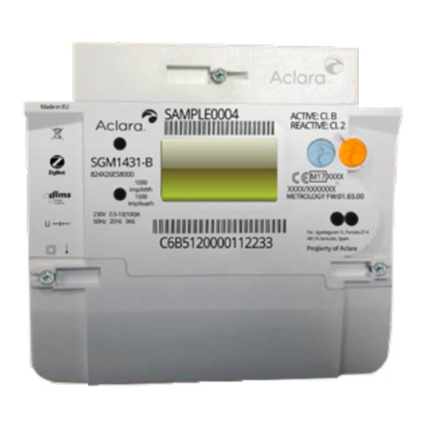
Aclara SGM3000 Series User manual

SGM3000 Series Smart Meters
User Manual
GEH-7111
Version 1.00 Revision 3

SGM3000 Series Smart Meters
User Manual
2
GEH-7111-1.00-2
Restricted
These instructions do not purport to cover all details or variations in equipment, nor to provide
for every possible contingency to be met during installation, operation, and maintenance. The
information is supplied for informational purposes only, and ACLARA makes no warranty as to
the accuracy of the information included herein. Changes, modifications and/or improvements
to equipment and specifications are made periodically and these changes may or may not be
reflected herein. It is understood that ACLARA may make changes, modifications, or
improvements to the equipment referenced herein or to the document itself at any time. This
document is intended for trained personnel familiar with the ACLARA products referenced
herein.
ACLARA may have patents or pending patent applications covering subject matter in this
document. The furnishing of this document does not provide any license whatsoever to any of
these patents.
This document contains proprietary information of ACLARA Company, USA and is furnished to
its customer solely to assist that customer in the installation, testing, operation, and/or
maintenance of the equipment described. This document shall not be reproduced in whole or
in part nor shall its contents be disclosed to any third party without the written approval of
ACLARA.
ACLARA provides the following document and the information included therein as is and
without warranty of any kind, expressed or implied, including but not limited to any implied
statutory warranty of merchantability or fitness for particular purpose.
If further assistance or technical information is desired, contact the nearest ACLARA Sales or
Service Office, or an authorized ACLARA Sales Representative.
© 2011 Aclara Inc., USA. All rights reserved.
Lexan™, MeterMate™, OPTOCOM™, Power Guard™, Site Genie™, Fitzall, IntellixTM, and
SMARTCOUPLER™ are trademarks of ACLARA
HomePlug® is a trademark of HomePlug Powerline Alliance.
ZigBee® is a trademark of ZigBee Alliance.
Issued: 8/2012
MODIFICATION RECORD
VERSION
REV.
DATE
AUTHOR
CHANGE DESCRIPTION
1.00
1
08.11
ACLARA
Created.
1.00
2
11.11
ACLARA
Meter name change from SM3000 to SGM3000
1.00
3
01.12
ACLARA
Minor technical updates
SCOPE OF AUTHENTICATION
VERSION
REV.
DATE
P.ENG
SCOPE OF AUTHENTICATION
1.00
1
08.25.2011
1.00
2
11.10.2011
1.00
3
01.16.2012

SGM3000 Series Smart Meters
User Manual
Restricted
GEH-7111-1.00-2
3
Contents
About this Document .......................................................................................................... 10
Purpose ..................................................................................................................................... 10
Intended Audience.................................................................................................................... 10
1 Before You Start ............................................................................................................... 11
Safety Precautions .................................................................................................................... 11
2 Product Description .......................................................................................................... 13
2.1 General Information ......................................................................................................... 14
2.2 Physical Components and Build Options .......................................................................... 15
2.3 Features ............................................................................................................................ 16
2.4 Operating Range............................................................................................................... 17
2.5 Meter Models (Physical Variants)..................................................................................... 17
SGM3011...................................................................................................................... 19
SGM3013...................................................................................................................... 19
SGM3022...................................................................................................................... 19
SGM3023...................................................................................................................... 19
SGM3030...................................................................................................................... 20
SGM3031...................................................................................................................... 20
SGM3033...................................................................................................................... 20
SGM30C2...................................................................................................................... 20
2.6 Backup Power Supply........................................................................................................ 20
Battery Backup............................................................................................................. 20
Super Capacitor Backup ............................................................................................... 20
2.7 Communications Features and Functionality ................................................................... 20
Optical Port .................................................................................................................. 21
Serial Port..................................................................................................................... 21
WAN Antenna .............................................................................................................. 22
Advanced Metering Infrastructure (AMI) Interface..................................................... 22
ZigBee Interface ........................................................................................................... 22
2.8 Meter Security .................................................................................................................. 23
Meter Cover ................................................................................................................. 23
Terminal Cover............................................................................................................. 24
Internal Temperature Sensing ..................................................................................... 25
Security Sticker............................................................................................................. 26
2.9 Liquid Crystal Display ........................................................................................................ 26
2.10 Memory............................................................................................................................. 26
2.11 Relays ................................................................................................................................ 27

SGM3000 Series Smart Meters
User Manual
4
GEH-7111-1.00-2
Restricted
Primary Supply Disconnect (Nominal 100 A) Relay ................................................... 27
Auxiliary Load Control (Nominal 32 A) Relay............................................................. 27
External Disconnect (Nominal 2 A) Relay .................................................................. 27
Relay Status................................................................................................................ 27
Physical Button Interface........................................................................................... 27
2.12 Physical Buttons................................................................................................................ 28
2.13 Firmware Variants............................................................................................................. 28
2.14 Firmware Specifications.................................................................................................... 29
2.15 Firmware Upgrade ............................................................................................................ 30
3 Metrology Functionality.................................................................................................... 31
3.1 Multipurpose Energy Metering ........................................................................................ 31
Electricity Observables................................................................................................. 31
Water Observables ...................................................................................................... 33
Gas Observables........................................................................................................... 33
Summations ................................................................................................................. 34
3.2 Data Storage...................................................................................................................... 34
Data Storage Formats .................................................................................................. 34
Demand Calculations ................................................................................................... 35
Demand Reset.............................................................................................................. 36
Data Accumulations ..................................................................................................... 36
Storage of Accumulation/Demand Data...................................................................... 36
3.3 Load Profile Storage.......................................................................................................... 37
Memory Requirements................................................................................................ 37
Time of Use Storage..................................................................................................... 38
Number of Rates .......................................................................................................... 38
Daily Time Periods........................................................................................................ 38
Calendar Definition ...................................................................................................... 38
Storage of TOU Data .................................................................................................... 39
Resetting Time of Use Accumulation Registers ........................................................... 40
3.4 Prepayment Operation ..................................................................................................... 40
Overdraft Facility.......................................................................................................... 40
Critical Peak Pricing...................................................................................................... 40
4 Advanced Features ........................................................................................................... 42
4.1 Supply Disconnect and Reconnect.................................................................................... 42
General Specifications.................................................................................................. 42
4.2 Supply Disconnection........................................................................................................ 43
Supply Disconnection Reconnection Event Priority..................................................... 43
4.3 Scheduled Disconnection/Reconnection.......................................................................... 44
4.4 Automatic Disconnection.................................................................................................. 46
Automatic Disconnection: Supply Capacity (Power Usage) for Delivered Energy ...... 46

SGM3000 Series Smart Meters
User Manual
Restricted
GEH-7111-1.00-2
5
Automatic Disconnection: Supply Capacity for Received Energy................................ 47
Automatic Disconnection: Insufficient Prepaid Funds ................................................ 47
Automatic Disconnection: Safety Alerts ...................................................................... 48
Automatic Disconnection: Under Frequency Load Shedding ...................................... 48
Reconnection Event Generation After Automatic Disconnection............................... 49
4.5 Supply Reconnection ........................................................................................................ 49
Managing Power Loss Condition.................................................................................. 49
Arming and Disarming ................................................................................................. 49
Arming Time Out Period .............................................................................................. 50
Attempting to Remotely Reconnect an Armed Meter ................................................ 50
Armed State After Power Outage................................................................................ 50
Auto-Disconnect After Remote Reconnection ............................................................ 50
4.6 Real Time Clock................................................................................................................. 50
Setting Date and Time.................................................................................................. 51
Date and Time Format ................................................................................................. 51
4.7 Auxiliary Load Control....................................................................................................... 52
General Specifications.................................................................................................. 52
Load Control Relay Visual Status ................................................................................. 52
Restriction to Protect Critical Customers .................................................................... 53
Auxiliary Load Control Event Priority........................................................................... 53
Emergency Override via Control Groups ..................................................................... 54
Primary Load Control Group ........................................................................................ 55
Secondary Load Control Group.................................................................................... 55
Tertiary Load Control Group ........................................................................................ 55
Load Control Emergency Override State ..................................................................... 55
4.8 Load Cycling ...................................................................................................................... 55
4.9 Boost Capability ................................................................................................................ 56
Boost Primacy .............................................................................................................. 56
4.10 Randomization .................................................................................................................. 56
5 Technical Information....................................................................................................... 58
5.1 Technical Information...................................................................................................... 58
5.2 Reference Voltage and Frequency.................................................................................. 58
Relay Status.................................................................................................................. 59
6 Installation Instructions .................................................................................................... 60
6.1 Terminal Connections ....................................................................................................... 60
Terminal Block.............................................................................................................. 60
Single Phase Terminal Arrangements .......................................................................... 60
6.2 Three Phase Terminal Arrangements ............................................................................... 63
Terminal Guard ............................................................................................................ 65
6.3 AMI Cartridge.................................................................................................................... 65

SGM3000 Series Smart Meters
User Manual
6
GEH-7111-1.00-2
Restricted
6.4 Voltage Test Link............................................................................................................... 65
6.5 Backup Power Supply........................................................................................................ 65
Mounting Template ..................................................................................................... 66
6.6 Requirements and Installation Procedure........................................................................ 66
7 Operating Instructions ...................................................................................................... 68
7.1 Meter Nameplate.............................................................................................................. 68
7.2 Meter Display.................................................................................................................... 69
Scroll Switch Actions .................................................................................................... 69
Liquid Crystal Display Information............................................................................... 70
Liquid Crystal Display Symbols..................................................................................... 70
8 Maintenance Instructions ................................................................................................. 75
8.1 Recommended Procedures............................................................................................... 75
Meter Testing Tools ..................................................................................................... 75
8.2 Field Accuracy Test ........................................................................................................... 76
Watt Hour Test Procedure........................................................................................... 77
8.3 Battery Maintenance ........................................................................................................ 77
8.4 Service............................................................................................................................... 77
8.5 Repair................................................................................................................................ 78
8.6 Returning a Meter............................................................................................................. 78
8.7 Cleaning............................................................................................................................. 78
8.8 Storage .............................................................................................................................. 78
8.9 Errors and Cautions........................................................................................................... 78
Error Reporting ............................................................................................................ 78
Caution Reporting ........................................................................................................ 81
9 Specifications ................................................................................................................... 85
10 Meter Diagrams.............................................................................................................. 91

SGM3000 Series Smart Meters
User Manual
Restricted
GEH-7111-1.00-2
7
Figures
Figure 1 SGM3000 Series Smart Meters...................................................................................... 13
Figure 2 SGM3000 Series Model Nomenclature ......................................................................... 18
Figure 3 SGM3000 Smart Meter Family....................................................................................... 19
Figure 4 Optical Ports................................................................................................................... 21
Figure 5 Meter Cover Seal............................................................................................................24
Figure 6 Terminal Cover Seal .......................................................................................................25
Figure 7 Data Storage Formats .................................................................................................... 35
Figure 8 SGM3000 Series Block Diagram..................................................................................... 58
Figure 9 SGM3011 Terminal Connections ................................................................................... 61
Figure 10 SGM3013 Terminal Connections ................................................................................. 61
Figure 11 SGM3022 Terminal Connections ................................................................................. 62
Figure 12 SGM3023 Terminal Connections ................................................................................. 63
Figure 13 SGM3030 Terminal Connections ................................................................................. 63
Figure 14 SGM3031 Terminal Connections ................................................................................. 64
Figure 15 SGM3033 Terminal Connections ................................................................................. 64
Figure 16 SGM30C2 Terminal Connections ................................................................................. 65
Figure 17 Mounting Hole Spacing (Suspension Triangle) ............................................................ 66
Figure 18 SGM3000 Meters Mounting Detail.............................................................................. 67
Figure 19 SGM3000 Meter Nameplate........................................................................................ 68
Figure 20 SGM3000 Liquid Crystal Display .................................................................................. 70
Figure 21 Liquid Crystal Display Information............................................................................... 71
Figure 22 LCD Relay Status........................................................................................................... 71
Figure 23 LCD Phase Voltage Status ............................................................................................ 71
Figure 24 LCD Current Status....................................................................................................... 72
Figure 25 LCD Numeric Data Values ............................................................................................ 72
Figure 26 LCD Units and Currency Status .................................................................................... 72
Figure 27 LCD Data Identifier.......................................................................................................73
Figure 28 LCD Time of Use (TOU) Indicator ................................................................................. 73

SGM3000 Series Smart Meters
User Manual
8
GEH-7111-1.00-2
Restricted
Figure 29 LCD Communication Status.......................................................................................... 73
Figure 30 LCD AMI Signal Strength Status ................................................................................... 73
Figure 31 LCD Low Battery Indicator ........................................................................................... 74
Figure 32 LCD Warning/Alert Indicator ....................................................................................... 74
Figure 33 Pulse Output Ports ....................................................................................................... 75
Figure 34 SGM3000 Liquid Crystal Display .................................................................................. 76
Figure 35 SGM3000 Single Phase Meter Diagram....................................................................... 91
Figure 36 SGM3000 Three Phase Meter Diagram ....................................................................... 92

SGM3000 Series Smart Meters
User Manual
Restricted
GEH-7111-1.00-2
9
Tables
Table 1 Operating Range.............................................................................................................. 17
Table 2 SGM3000 Series Smart Meter Family Variants............................................................... 18
Table 3 AMI Interface Definition..................................................... Error! Bookmark not defined.
Table 4 Metrology and Application Processor Firmware Variants.............................................. 28
Table 5 Summary of High Level Options for the SGM3000 Meter Variants................................ 42
Table 6 Summary of High Level Options for SGM3000 Meter Variants...................................... 52
Table 7 SGM3000 Voltage Ranges 230 V ±20% ........................................................................... 59
Table 10 Meter Terminal Configuration Summary...................................................................... 60
Table 13 Error Code Display......................................................................................................... 79
Table 14 Er 000 002 ..................................................................................................................... 79
Table 16 Er 000 200 ..................................................................................................................... 80
Table 17 Er 001 000 ..................................................................................................................... 80
Table 18 Er 100 000 ..................................................................................................................... 80
Table 19 Caution Code Display .................................................................................................... 81
Table 20 Fault Symptoms Without Codes ................................................................................... 84
Table 21 SGM3011 Specifications................................................................................................ 85
Table 22 SGM3013 Specifications................................................................................................ 85
Table 23 SGM3022 Specifications................................................................................................ 86
Table 24 SGM3023 Specifications................................................................................................ 87
Table 25 SGM3030 Specifications................................................................................................ 87
Table 26 SGM3031 Specifications................................................................................................ 88
Table 27 SGM3033 Specifications................................................................................................ 89
Table 28 SGM30C2 Specifications................................................................................................ 89
Table 29 Standards Compliance...................................................................................................90
Table 30 Standards Supported.....................................................................................................90

SGM3000 Series Smart Meters
User Manual
10
GEH-7111-1.00-2
Restricted
About this Document
Purpose
The purpose of this document is to describe the installation, operation, maintenance,
instructions for the SGM3000 Series Smart Meter family.
Warning: The information contained within this document is intended to be an aid to qualified
metering personnel. It is not intended to replace the extensive training necessary to install or
remove meters from service. Any work on or near energized meters, meter sockets, or other
metering equipment presents the danger of electrical shock. All work on these products must
be performed by qualified industrial electricians and metering specialists only. All work must be
done in accordance with local utility safety practices and procedures.
Intended Audience
This document is intended for extensively trained qualified metering personnel, industrial
electricians, and metering specialists only.

SGM3000 Series Smart Meters
User Manual
Restricted
GEH-7111-1.00-2
11
1 Before You Start
Read and thoroughly understand this guide before installing and operating the unit. Save these
instructions for later use and reference.
Warning: All procedures in this manual must be strictly adhered to. Any
deviation from these could cause irreversible damages to the meter and could lead to
property damage, personal injury, and/or death. Installation and maintenance of the meter
must be carried out by qualified personnel only.
Safety Precautions
Follow all safety precautions and instructions in this manual.
Only qualified personnel should work on the meter. Maintenance personnel should be familiar
with the technology and the hazards associated with electrical equipment.
•Never work alone.
•Before performing visual inspections, tests, or maintenance on this equipment, isolate
or disconnect all hazardous live circuits and sources of electric power. Assume that all
circuits are live until they have been completely de-energized, tested, and tagged. Pay
particular attention to the design of the power system. Consider all sources of power,
including the possibility of back feed.
•Turn off all power supplying the equipment in which the meter is to be installed before
installing and wiring the meter.
•Operate only from the power source specified on the installed power supply module.
•Beware of potential hazards and wear personal protective equipment.
•The successful operation of this equipment depends upon proper handling, installation,
and operation. Neglecting fundamental installation requirements may lead to personal
injury as well as damage to electrical equipment or other property.
•All electronic components within the meter are susceptible to damage from
electrostatic discharge. To prevent damage when handling this product use approved
static control procedures.
•Hazardous voltages can cause shock, burns or death. To prevent exposure to hazardous
voltages, disconnect and lock out all power sources before servicing and removing
components.

SGM3000 Series Smart Meters
User Manual
12
GEH-7111-1.00-2
Restricted
•If the meter is used in a manner not specified in this manual, the protection provided by
the equipment may be impaired.
•Changes or modifications made to the unit not authorized by ACLARA could void the
warranty.

SGM3000 Series Smart Meters
User Manual
Restricted
GEH-7111-1.00-2
13
2 Product Description
The SGM3000 Series Smart Meters family is comprised of eight electronic electricity meters,
both single phase and three phase. The eight SGM3000 Series meters are the SGM3011,
SGM3013, SGM3022, SGM3023, SGM3030, SGM3031, SGM3033, and SGM30C2. The single
phase meters (SGM3011, SGM3013, SGM3022, and SGM3023) all share the same housing and
footprint, and the three phase meters (SGM3030, SGM3031, SGM3033, SGM30C2) all share the
same housing and footprint. All the meters have a common layout for buttons, optical port,
display, and pulse indicators. The AMI modules are also shared across all meter models.
The SGM3000 Series Smart Meters provide full functionality metering. This includes select
measurements for billing, demand, and load profile storage, flexible calendar definition,
configurable Time of Use (TOU) operation, prepayment, configurable data display, independent
communication ports, AMI communication, advanced security and safety measures, and the
capacity to adapt to evolving technology.
Figure 1 SGM3000 Series Smart Meters

SGM3000 Series Smart Meters
User Manual
14
GEH-7111-1.00-2
Restricted
2.1 General Information
The key features of the SGM3000 Series Smart Meter family that differentiate it from earlier
meters include the following:
•Single and three phase direct connect and CT connect variants
•Up to two relays for load control
•Dedicated micro-generation model to support gross tariffs
•IEC protocol (DLMS/COSEM) as well as ANSI (C12. 18/19) software definable
•Full firmware updates (not patches)
•Dual firmware versions
•Greater memory for data storage
•Simultaneous local and remote communication without performance loss
•Truly field replaceable AMI module
•Consistent functionality with multiple AMI technologies as Smarts are under the meter
cover
•PLC back-haul support (with no exposed cables)
•Greater number of TOU rates to meet retailer needs and international standards
•Multiple load profiles
•Definable memory allocation per load profile
•ZigBee Home Area Network support independent of AMI module
•Smart Energy Profile on main application processor, not AMI module
•Under frequency load shedding on all relays
•Auxiliary load cycling
•Increased physical and electronic security (tamper, password levels)
•Prepayment using TOU rates with overdraft facility
•Load side voltage sensing for increased safety
•No user accessible compartments
•Complete terminal coverage for increased safety
•Mechanical design to support hiding of all communication and antenna cables to deter
tampering

SGM3000 Series Smart Meters
User Manual
Restricted
GEH-7111-1.00-2
15
2.2 Physical Components and Build Options
The SGM3000 Series Smart Meter family includes single phase meters, SGM3011, SGM3013,
SGM3022, and SGM3023, and three phase meters, SGM3030, SGM3031, SGM3033, and
SGM30C2.
The dimensions of the SGM3000 single phase meters are 259.7 mm height × 147 mm width ×
101.4 mm depth. The dimensions of the SGM3000 three phase meters are 289.7 mm height ×
173 mm width × 117.4 mm depth. The SGM3000 Series meters use a thermally stable, UV
protected plastic cover that is molded in one piece. The cover gives clear viewing of the meter
display and access to the Display Scroll and Load Control Boost. The cover also has an optical
communication port adhering to ANSI C12.18 or IEC 62056–21. The cover is secured by two
screws. Tamper resistance and indication is provided via wire and crimp seals and a tamper
detection mechanism.
The following lists the main physical components shared by all of the SGM3000 Series meters:
•A base component
•Brass barrel terminals, relays, and shunt/CTs fixed to the base of the meter
•A heat isolator that covers the terminal, relay, shunt/CT section, providing the infinity shape
guard for the terminal screws
•A mounted power supply board and metering board
•Optional HAN and control circuit boards
•An outer cover that protects all internal circuitry
•A backup power source and AMI cartridge
•A terminal guard that covers the terminals and exposed conductor wires
•A terminal cover that hides all internal components once fitted
The SGM3000 Series meters also support a range of factory build options that impact the
upgradability of the meter post factory build.
These options must be made at factory build time:
•The selection the terminal arrangement
•The selection of the optical port type (IEC versus ANSI)
•HAN options
These options may be installed post factory build:
•The backup power supply type (battery versus super capacitor) can be changed—
Installation will require the removal of the terminal cover.
•The AMI cartridge can be changed —Installation will require the removal of the terminal
cover.

SGM3000 Series Smart Meters
User Manual
16
GEH-7111-1.00-2
Restricted
2.3 Features
The SGM3000 Series Smart Meter family has the following main features:
•16 MB of SDRAM (Synchronous Dynamic Random Access Memory) used for running the
high speed applications, 4 MB of Serial Flash Memory used to maintain the larger amounts
of data, and 64 kB or EEPROM (Electrically Erasable Programmable Read-Only Memory)
used for storing the most important generated data
•Configurable Data Display, with auto and manual scroll lists and user defined fields
•Independent communication ports: Local optical port, AMI interface port, ZigBee HAN port,
and power line interface port.
•Configurable Time of Use (TOU) operation to support full flexibility tariffing
•Flexible calendar definition that supports up to 8 daily time periods, 4 day types, 50
designated holidays or special days, and 4 seasons
•Configurable measurement profile with independent measurements for each measuring
element
•Select demand measurement for demand calculation including selected measurement
profile, selectable demand interval, block versus rolling demand, and support for
cumulative demand
•Prepayment mode of operation
•Replaceable AMI communication design
•Firmware selectable configuration to support both ANSI C12.18/19 and COSEM/DLMS

SGM3000 Series Smart Meters
User Manual
Restricted
GEH-7111-1.00-2
17
2.4 Operating Range
Table 1 Operating Range
Voltage
127V , 220 V to 240 V ± 20%
Operating Temperature
−25 °C to +60 °C
(−40 °C to +70 °C limit range of operation)
Storage Temperature
−40 °C to +70° C
Relative Humidity
non-condensing
Intended Use
Outdoor
Frequency
50 Hz
Starting Currents
Direct connect meters = 45 mA
SGM30C2 CT connect = 3 mA
Power Consumption (excluding communication
modules)
1.2 W for Single Phase
1.7 W for Three Phase
Accuracy
Class 1 per IEC® 62053–21 / Class 2 per IEC 62053–
23
Current
100 A (maximum)
10 A (basic)
Enclosure
IP54 (IEC 60529, 2001 –2002 Edition 2.1, outdoor
rating).
Insulation Class Index
Protective Class II
Mechanical Rating (Vibration & Shock)
The meter is designed to work in mechanical
environments classified as class M1 as described in
DIRECTIVE 2004/22/EC OF THE EUROPEAN
PARLIAMENT AND OF THE COUNCIL of 31 March
2004 on measuring instruments. This class allows the
instruments to be used in locations with vibration and
shocks of low significance.
Electromagnetic Rating
The meter is designed to work in Electromagnetic
environments classified as class E2 as described in
DIRECTIVE 2004/22/EC OF THE EUROPEAN
PARLIAMENT AND OF THE COUNCIL of 31 March
2004 on measuring instruments. This class allows the
instruments to be used in locations with
electromagnetic disturbances corresponding to those
normally to be found in industrial buildings.
2.5 Meter Models (Physical Variants)
The SGM3000 Series Smart Meters family is made up of eight meters that share common
physical characteristics and functionality.

SGM3000 Series Smart Meters
User Manual
18
GEH-7111-1.00-2
Restricted
The nomenclature of the meter models will follow a four digit scheme as shown below.
Figure 2 SGM3000 Series Model Nomenclature
•The first digit represents the major version/generation number.
•The second digit represents the minor version/generation number.
•The third digit represents the number of elements in the meter.
The only exception is the CT connect meter where the letter C will be used instead of a
number.
•The fourth digit represents the number of relays in the meter.
The following table summarizes the eight meters in the SGM3000 Series Smart Meters family.
Table 2 SGM3000 Series Smart Meter Family Variants
Model
Connect
Type
Phases
Current
Elements
100 A Main
Disconnect
32 A Load
Control
2 A Load
Control
Current
Max
(Basic)
SGM3011
Direct
Single
1
Yes
No
No
100 (10)
SGM3013
Direct
Single
1
Yes
Yes
Yes
100 (10)
SGM3022
Direct
Single
2
Yes
Yes
No
100 (10)
SGM3023
Direct
Single
2
Yes
Yes
Yes
100 (10)
SGM3030
Direct
Three
3
No
No
No
100 (10)
SGM3031
Direct
Three
3
Yes
No
No
100 (10)
SGM3033
Direct
Three
3
Yes
Yes
Yes
100 (10)
SGM30C2
CT
Three
3
2 A Relay
No
Yes
5 (1)

SGM3000 Series Smart Meters
User Manual
Restricted
GEH-7111-1.00-2
19
Figure 3 SGM3000 Smart Meter Family
SGM3011
The SGM3011 model is a single phase single element meter with a 100 A main supply relay.
SGM3013
The SGM3013 model is a single phase single element meter with a 100 A main supply relay, a
32 A load control relay, and a 2 A load control relay.
SGM3022
The SGM3022 model is a single phase dual element meter with a 100 A main supply relay and a
32 A load control relay.
The SGM3022 meter has a dedicated terminal connected to the second element to support
connection of micro-generation power systems and will measure the energy provided by the
micro-generation system prior to any energy being consumed to support gross tariff markets.
The 32 A load control relay is measured by the primary element.
SGM3023
The SGM3023 model is a single phase dual element meter with a 100 A main supply relay, a 32
A load control relay, and a 2 A load control relay.
The second element of SGM3023 meter will measure the energy consumed by both auxiliary
loads.

SGM3000 Series Smart Meters
User Manual
20
GEH-7111-1.00-2
Restricted
SGM3030
The SGM3030 meter is a three phase three element meter with no main supply relay and no
load control relay.
SGM3031
The SGM3031 meter is a three phase three element meter with a 100 A main supply relay and
no load control relays.
SGM3033
The SGM3033 model is a three phase three element meter with a 100 A main supply relay, a 32
A load control relay, and a 2 A load control relay.
SGM30C2
The SGM30C2 model is a three phase three element CT connect meter with two 2 A auxiliary
load control relays.
2.6 Backup Power Supply
The SGM3000 Series meters have a physical backup power supply, either a battery or a super
capacitor, that is used to maintain the clock mechanism when mains supply is not available. The
backup power source can be replaced post-production of the meter.
Battery Backup
The SGM3000 Series meters are available with a battery backup option. The backup battery will
have sufficient capacity to maintain the meter timing mechanism for a total period of 2 years
when off the main supply. The battery is a Lithium battery and is not rechargeable. The
operational life is 10 years.
Super Capacitor Backup
The SGM3000 Series meters are available with a super capacitor backup option. The backup
super capacitor will have sufficient capacity to maintain the meter timing mechanism for a total
period of 3 days when off the main supply. The super capacitor will recharge when the main
supply is available. The super capacitor has an operational life of 2.2 years.
2.7 Communications Features and Functionality
The SGM3000 Series meter supports advanced metering infrastructure (AMI). The meter also
integrates ZigBee to enable communication over Home Area Network (HAN) for monitoring and
controlling in-home devices.
The SGM3000 Series meter will have independent communication ports so that it supports
communication via the optical port at the same time as communication via the AMI interface or
serial ports.
This manual suits for next models
8
Table of contents
Other Aclara Measuring Instrument manuals