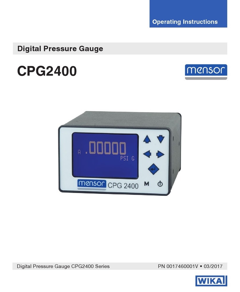
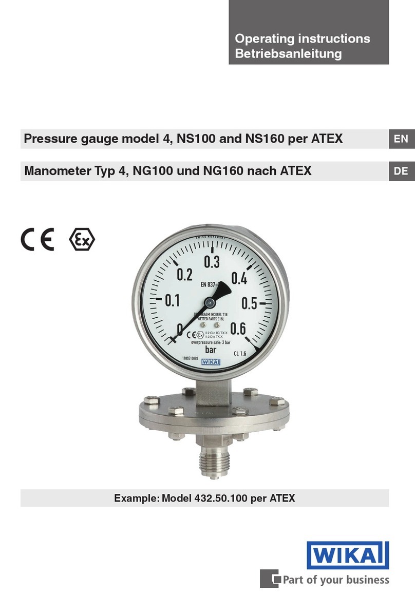
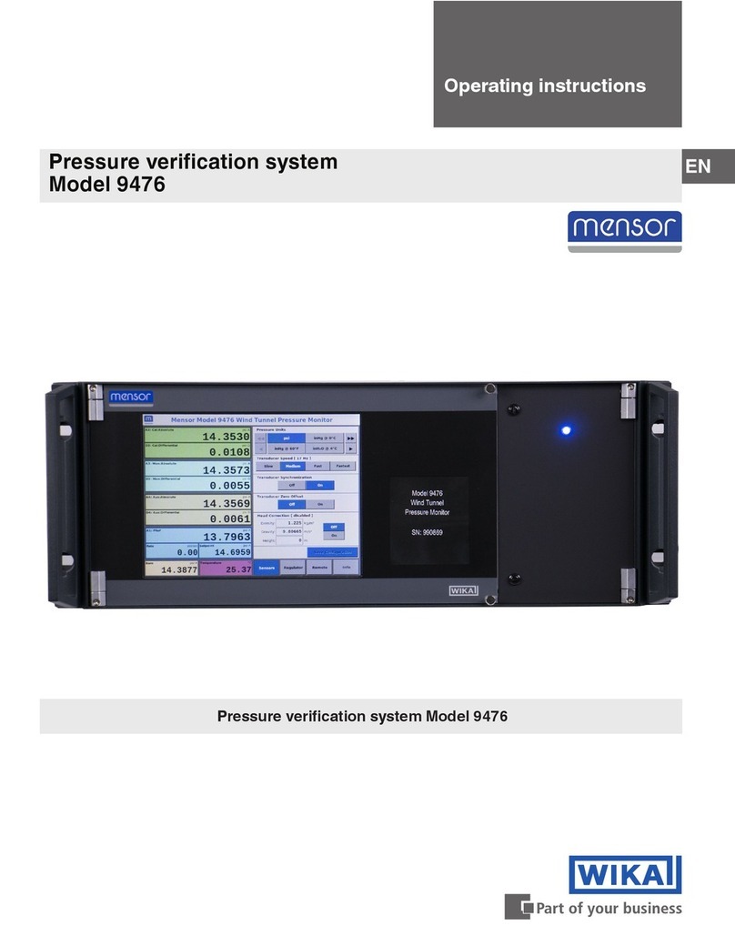
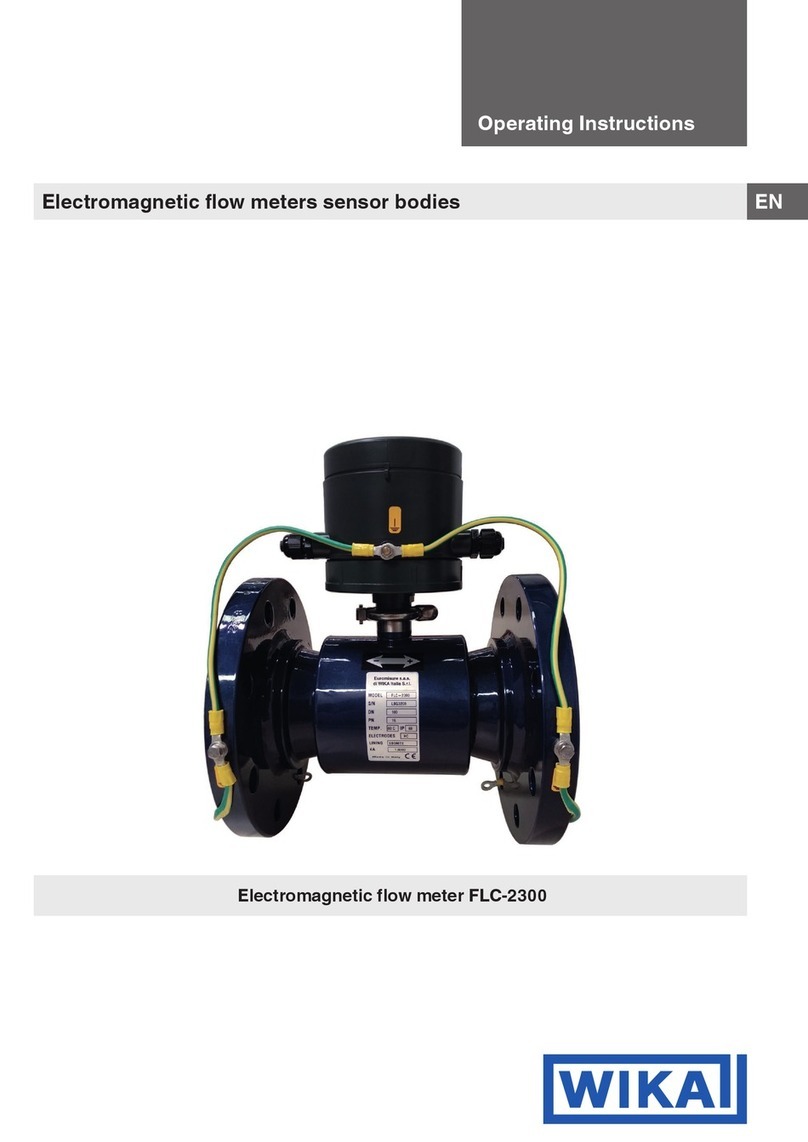
WIKA 821 User manual

Operating instructions
Betriebsanleitung
Mode d'emploi
Manual de instrucciones
GB
Magnetic snap-action contact model 821
in pressure and temperature gauges
Magnetspringkontakt Typ 821
in Druck- und Temperaturmessgeräten
Contact sec magnétique type 821
de manomètres et thermomètres
Contacto magnético de ruptura brusca modelo 821
en manómetros y termómetros
Magnetic snap-action contact
model 821.21 in pressure gauge
model 212.20.100
D
F
E
Magnetic snap-action
contact model 821.12

WIKA operating instructions magnetic snap-action contact model 821
GB
2
2003325.03 03/2011 GB/D/F/E
Operating instructions model 821 Page 3-18
Betriebsanleitung Typ 821 Seite 19-34
Mode d'emploi type 821 Page 35-50
Manual de instrucciones modelo 821 Página 51-66
D
F
E
© 2011 WIKA Alexander Wiegand SE & Co. KG
All rights reserved. / Alle Rechte vorbehalten.
WIKA®is a registered trademark in various countries.
WIKA®ist eine geschützte Marke in verschiedenen Ländern.
Prior to starting any work, read the operating instructions!
Keep for later use!
Vor Beginn aller Arbeiten Betriebsanleitung lesen!
Zum späteren Gebrauch aufbewahren!
Lire le mode d‘emploi avant de commencer toute opération !
A conserver pour une utilisation ultérieure !
¡Leer el manual de instrucciones antes de comenzar cualquier trabajo!
¡Guardar el manual para una eventual consulta posterior!

WIKA operating instructions magnetic snap-action contact model 821 3
GB
2003325.03 03/2011 GB/D/F/E
Contents
1. General information 4
2. Safety 5
3. Specications 8
4. Overcurrent protectors 10
5. Allocation of switch version to basic instruments
and measuring ranges 11
6. Design and function 12
7. Transport, packaging and storage 12
8. Commissioning, operation 13
9. Contact protection measures 15
10. Maintenance and cleaning 18
11. Dismounting and disposal 18
Contents

WIKA operating instructions magnetic snap-action contact model 821
GB
4
2003325.03 03/2011 GB/D/F/E
1. General information
■
The magnetic snap-action contact described in the operating
instructions has been designed and manufactured by state-of-the-
art knowledge. All components are subject to stringent quality and
environmental criteria during production. Our management systems
are certied to ISO 9001 and ISO 14001.
■
These operating instructions contain important information on
handling the magnetic snap-action contact. Working safely requires
that all safety instructions and work instructions are observed.
■
Observe the relevant local accident prevention regulations and
general safety regulations for the magnetic snap-action's range of
use.
■
The operating instructions are part of the product and must be kept in
the immediate vicinity of the instruments with magnetic snap-action
contacts and readily accessible to qualied personnel at any time.
■
Skilled personnel must have carefully read and understood the
operating instructions prior to beginning any work.
■
The manufacturer's liability is void in the case of any damage caused
by using the product contrary to its intended use, non-compliance
with these operating instructions, assignment of insuciently
qualied skilled personnel or unauthorised modications to the
instrument.
■
The general terms and conditions, contained in the sales
documentation, shall apply.
■
Subject to technical modications.
■
Further information:
- Internet address: www.wika.de / www.wika.com
- Application consultant: Tel.: (+49) 9372/132-0
Fax: (+49) 9372/132-406
E-Mail:inf[email protected]

WIKA operating instructions magnetic snap-action contact model 821 5
GB
2003325.03 03/2011 GB/D/F/E
1. General information / 2. Safety
Explanation of symbols
WARNING!
... indicates a potentially dangerous situation that can result
in serious injury or death, if not avoided.
Information
… points out useful tips, recommendations and information
for ecient and trouble-free operation.
2. Safety
WARNING!
Before installation, commissioning and operation, ensure
that the appropriate magnetive snap-action contact has
been selected in terms of design and specic measuring
conditions.
The instruments are no safety accessories as dened by
the pressure equipment directive 97/23/EC.
Non-observance can result in serious injury and/or damage
to the equipment.
Further important safety instructions can be found in the
individual chapters of these operating instructions.

WIKA operating instructions magnetic snap-action contact model 821
GB
6
2003325.03 03/2011 GB/D/F/E
2. Safety
2.1 Intended use
The model 821 magnetic snap-action contact is used for the switching
of switching currents up to max. 1 A.
The magnetic snap-action contact has been designed and built solely
for the intended use described here and may only be used accordingly.
The manufacturer shall not be liable for claims of any type based on
operation contrary to the intended use.
2.2 Personnel qualication
WARNING!
Risk of injury if qualication is insucient!
Improper handling can result in considerable injury and
damage to equipment.
■
The activities described in these operating instructions
may only be carried out by skilled personnel who have
the qualications described below.
Skilled personnel
Skilled personnel are understood to be personnel who, based on their
technical training, knowledge of measurement and control technology
and on their experience and knowledge of country-specic regulations,
current standards and directives, are capable of carrying out the work
described and of independently recognising potential hazards.
2.3 Special hazards
WARNING!
When installing, commissioning and operating these instru-
ments, observe the appropriate national safety regulations
(e.g. VDE 0100).

WIKA operating instructions magnetic snap-action contact model 821 7
GB
WARNING!
Only work on the gauge with the voltage disconnected.
WARNING!
Residual media in dismounted instruments can result in a
risk to persons, the environment and equipment.
Take sucient precautionary measures.
2.4 Labelling / Safety marks
Product label
Explanation of symbols
Before mounting and commissioning the magnetic snap-
action contact, ensure you read the operating instructions!
CE, Communauté Européenne
Instruments bearing this mark comply with the relevant
european directives.
Instruments bearing this mark on the dial are safety
pressure gauges with solid bae wall per EN 837 (S3).
2003325.03 03/2011 GB/D/F/E
2. Safety
Date of manufacture

WIKA operating instructions magnetic snap-action contact model 821
GB
8
2003325.03 03/2011 GB/D/F/E
3. Specications
3. Specications
Table 1a: Limits for the magnetic snap-action contact model 821
Limits for the contact rating
with resistive load
Magnetic snap-action contact
model 821
dry gauges lled gauges
Rated voltage Ue max. 250 V 250 V
Rated current 1)
Make current 1.0 A 1.0 A
Breaking current 1.0 A 1.0 A
Continuous current 0.6 A 0.6 A
Contact rating max. 30 W / 50 VA 20 W / 20 VA
1) The values for rated currents shown in the above table apply to instruments with switch ver-
sion S. For instruments with switch version L these values should be halved.
(see chapter "5. Allocation of switch version to basic instruments and measuring ranges")
WARNING!
None of the limits for voltage, current and power are to be
exceeded!
We recommend the following load values to ensure safe,
continuous operation:
Table 1b: Limits for the sliding contact model 811
Limits for the contact rating
with resistive load
Sliding contact model 811
dry gauges
Rated voltage Ue max. 250 V
Rated current 1)
Make current 0.7 A
Breaking current 0.7 A
Continuous current 0.6 A
Contact rating max. 10 W / 18 VA

WIKA operating instructions magnetic snap-action contact model 821 9
GB
2003325.03 03/2011 GB/D/F/E
Voltage
(DIN IEC 38)
Magnetic snap-action contact model 821
dry gauges lled gauges
DC / AC
V
resistive
load
DC
mA
AC
mA
inductive
load
cos ϕ >0.7
mA
resistive
load
DC
mA
AC
mA
inductive
load
cos ϕ >0.7
mA
230 100 120 65 65 90 40
110 200 240 130 130 180 85
48 300 450 200 190 330 130
24 400 600 250 250 450 150
Table 2a: Recommended contact rating for the magnetic snap-action
contact model 821
3. Specications
Voltage
(DIN IEC 38)
Sliding contact model 811
dry gauges
DC / AC
V
resistive load
DC
mA
AC
mA
inductive load
cos ϕ >0.7
mA
230 40 45 25
110 80 90 45
48 120 170 70
24 200 350 100
Table 2a: Recommended contact rating for the sliding contact model 811
The switching current must not be less than 20 mA with low
voltages for switching reliability reasons. For higher loads,
and instruments with liquid-lled cases, we recommend
using WIKA contact protection relays, models 905.1x.
The ingress protection to EN 60529 against external inuences depends
on the basic instrument and is found in the respective data sheet.
The limit switches can be used in the range from -20 to +70 °C. Where
the permissible temperatures for the basic instrument (see data sheet)
deviate from this range, the lower values are valid.
For further specications see the corresponding WIKA data sheet and
the order documentation.

WIKA operating instructions magnetic snap-action contact model 821
GB
10
2003325.03 03/2011 GB/D/F/E
4. Overcurrent protectors
The instruments do not provide for incorporated overcurrent protectors.
Should protectors be required, we recommend the following values in
accordance with EN 60947-5-1.
Table 3a: Overcurrent protectors with magnetic snap-action contact
Table 3b: Overcurrent protectors with sliding contact
Voltage Magnetic snap-action contact model 821
Switch version S 1) Switch version L 1)
V
Nominal size of instrument
63 100 160
Nominal size of instrument
63 100 160
24 1 A 2 A 2 A 0.63 A 1 A 1 A
250 0.63 A 1 A 1 A 0.315 A 0.63 A 0.63 A
Voltage Sliding contact model 811
Switch version S 1) Switch version L 1)
V
Nominal size of instrument
63 100 160
Nominal size of instrument
63 100 160
24 0.63 A 1 A 1 A 0.315 A 0.63 A 0.63 A
250 0.125 A 0.315 A 0.315 A 0.063 A 0.125 A 0.125 A
All data refer to miniature fuses M and a maximum short circuit current
of 100 A.
1) see chapter "5. Allocation of switch version to basic instruments and measuring ranges".

WIKA operating instructions magnetic snap-action contact model 821 11
GB
2003325.03 03/2011 GB/D/F/E
WIKA basic
instrument model
Nominal size Number of
contacts
Measuring
spans
Switch
version
2xx.xx 100 and 160 1≤ 1 bar L
2xx.xx 100 and 160 2≤ 1.6 bar L
2xx.xx 100 3 or 4 ≤ 4 bar L
2xx.xx 160 3 or 4 ≤ 2.5 bar L
214.11 96x96 and 144x144 1≤ 1 bar L
214.11 96x96 and 144x144 2≤ 1.6 bar L
214.11 96x96 3≤ 4 bar L
214.11 144x144 3≤ 2.5 bar L
5. Allocation of switch version to basic instruments ...
All other model 2 instruments are manufactured with switch
version S.
For model 3, 4, 5, 6 and 7 as well as model 55 and 73 instruments
switch version L is used.
5. Allocation of switch version to basic instruments and
measuring ranges
Depending on the basic instrument model, measuring range and number
of limit switches the switch versions S and L are used. The following table 4
shows the model 2 instruments with the allocated switch version L.
Table 4: Allocation of switch version to basic instruments and measuring
ranges

WIKA operating instructions magnetic snap-action contact model 821
GB
12
2003325.03 03/2011 GB/D/F/E
6. Design and function / 7. Transport, packaging ...
6. Design and function
6.1 Description
The built-in electrical switch contacts (magnetic snap-action or sliding
contacts) are auxiliary current switches which open or close connected
electric circuits at the set limits via the contact arm which is moved by
the actual value pointer.
6.2 Scope of delivery
Cross-check scope of delivery with the delivery note.
7. Transport, packaging and storage
7.1 Transport
Check the instrument for any damage that may have been caused during
transportation.
Obvious damage must be reported immediately.
7.2 Packaging
Do not remove packaging until just before mounting.
Keep the packaging as it will provide optimum protection during trans-
port (e.g. change in installation site, sending for repair).
7.3 Storage
Permissible conditions at the place of storage:
Storage temperature: In accordance with measuring instrument

WIKA operating instructions magnetic snap-action contact model 821 13
GB
Correct sealing of pressure gauge connections with parallel threads
must be made using suitable sealing rings, sealing washers or WIKA
prole seals. The sealing of tapered threads (e.g. NPT threads) is made
by providing the thread
, with additional sealing material such as, for
example, PTFE tape (EN 837-2).
The torque depends on the seal used. Connecting the gauge using
a clamp socket or a union nut is recommended, so that it is easier to
orientate the gauge correctly. When a blow-out device is tted to a
pressure gauge, it must be protected against being blocked by debris
and dirt.
2003325.03 03/2011 GB/D/F/E
Spanner ats Sealing in the
thread
Sealing face
Installation with
open-ended spanner
8. Commissioning, operation
8.1 Mechanical connection
In accordance with the general technical regulations for pressure
gauges (e.g. EN 837-2 "Selection and installation recommendations for
pressure gauges" and/or EN 13190 "Dial indicating thermometers").
When screwing gauges in, the force required for this must not be
applied through the case or the cable terminal box, but rather through
the spanner ats (using a suitable tool) provided for this purpose on the
square shaft of standard connections.

WIKA operating instructions magnetic snap-action contact model 821
GB
14
2003325.03 03/2011 GB/D/F/E
8. Commissioning, operation
With safety pressure gauges (see dial symbol
k
) ensure that the free
space behind the blow-out back is at least 15 mm.
8.2 Special requirements for the installation point
The instruments must be mounted in a location free from vibration in order to
avoid contact chatter and the resulting increased wear.
If the line to the measuring instrument is not adequately stable, a measuring
instrument holder should be used for fastening (and possibly via a exible
capillary). If vibrations cannot be avoided by means of suitable instal-
lation, instruments with liquid lling should be used. The instruments
should be protected against coarse dirt and wide uctuations in ambient
temperature.
8.3 Electrical connection
The electrical connection must only be made by qualied skilled
personnel. Connection details and switching functions are given on
the product label. Connection terminals and earth terminal are appro-
priately marked.The mains connection lines to be provided must be
dimensioned for maximum instrument power consumption and comply
with IEC 227 or IEC 245. Power ratings (see "Specications") and
protective circuits with inductive and capacitive loads see chapter
"9. Contact protection measures".

WIKA operating instructions magnetic snap-action contact model 821 15
GB
2003325.03 03/2011 GB/D/F/E
8. Commisioning, operation / 9. Contact protection ...
8.4 Adjusting the set pointers
The setting of the set points is achieved using the adjustment lock in the
window with the aid of the adjustment key (part of the scope of delivery;
found in standard instruments on the side of the terminal box).
The set pointers for the limit switches are freely adjustable over the full
scale range. For reasons of switching accuracy, switching reliability and
service life of the mechanical measuring systems, the switch points
should be between 10 % and 90 % of the measuring span.
Commissioning
During the commissioning process pressure surges must be avoided at
all costs. Open the shut-o valves slowly.
9. Contact protection measures
Mechanical contacts must not exceed the specied electrical values for
switching current and switching voltage independent of each other, not
even for a short time only.
For capacitive or inductive loads we recommend one of the following
protective circuits:
Set pointer
Adjustment lock
Removable
adjustment key

WIKA operating instructions magnetic snap-action contact model 821
GB
16
2003325.03 03/2011 GB/D/F/E
9. Contact protection measures
9.1. Inductive load with DC voltage
With DC voltage the contact protection can be achieved via a free-
wheeling diode, connected in parallel to the load. The polarity of the
diode must be arranged so that it closes when the operating voltage is
on.
Example:
Contact protection
measure with free-
wheeling diode
Contact
Diode
Contact
Contact
9.2. Inductive load with AC voltage
With AC voltage two protection measures are possible:
Example:
Contact protec-
tion measure with
voltage-depend-
ent resistor VDR
Example:
Contact protection
measure with RC
element

WIKA operating instructions magnetic snap-action contact model 821 17
GB
2003325.03 03/2011 GB/D/F/E
Contact
Contact
Switching voltage
Switching current
max. current
max. voltage
limit curve allowed working
range
Vmax
Amax
A
V
Amin
Vmin
9. Contact protection measures
9.3. Capacitive load
With capacitive loads elevated switch-on currents arise. These can be
reduced by series-connecting resistors in the supply line.
Examples:
Contact protec-
tion measure with
current-limiting
resistor
Contact curve
The hatched area of the contact curve shows the permissible electrical
values for the respective contact.
Accordingly the voltage and/or current to be switched must not exceed
the respective maximum values.
The power to be switched may only lie below the limit curve.

WIKA operating instructions magnetic snap-action contact model 821
GB
18
2003325.03 03/2011 GB/D/F/E
10. Maintenance and cleaning
10.1 Maintenance
The instruments are maintenance-free.The indicator and switching
function should be checked once or twice every year. For this the
instrument must be disconnected from the process to check with a
pressure or temperature testing device.
Repairs must only be carried out by the manufacturer or appropriately
qualied skilled personnel.
10.2 Cleaning
CAUTION!
■
Clean the instrument with a moist cloth.
■
Wash or clean the dismounted instrument before
returning it, in order to protect personnel and the
environment from exposure to residual media.
10. Maintenance and cleaning / 11. Dismounting and ...
11. Dismounting and disposal
WARNING!
Residual media in dismounted pressure or temperature
measuring instruments can result in a risk to persons, the
environment and equipment. Take sucient precautionary
measures.
11.1 Dismounting
Only disconnect the instrument once the system has been depressurised!
When dismounting, close the compensating valve (if available).
Risk of burns with temperature measuring instrument!
Let the instrument cool down suciently before dismounting! During
dismounting there is a risk of dangerously hot pressure media escaping.
11.2 Disposal
Incorrect disposal can put the environment at risk. Dispose of instrument
components and packaging materials in an environmentally compatible
way and in accordance with the country-specic waste disposal
regulations.

WIKA Betriebsanleitung Magnetspringkontakt Typ 821
D
2003325.03 03/2011 GB/D/F/E
19
1. Allgemeines 20
2. Sicherheit 21
3. Technische Daten 24
4. Überstrom-Schutzeinrichtungen 26
5. Zuordnung Schalterversion zu Grundgeräten und
Messbereichen 27
6. Aufbau und Funktion 28
7. Transport, Verpackung und Lagerung 28
8. Inbetriebnahme, Betrieb 29
9. Kontaktschutzmaßnahmen 31
10. Wartung und Reinigung 34
11. Demontage und Entsorgung 34
Inhalt
Inhalt

D
WIKA Betriebsanleitung Magnetspringkontakt Typ 821
2003325.03 03/2011 GB/D/F/E
20
1. Allgemeines
1. Allgemeines
■
Der in der Betriebsanleitung beschriebene Magnetspringkontakt wird
nach den neuesten Erkenntnissen konstruiert und gefertigt.
Alle Komponenten unterliegen während der Fertigung strengen
Qualitäts- und Umweltkriterien. Unsere Managementsysteme sind
nach ISO 9001 und ISO 14001 zertiziert.
■
Diese Betriebsanleitung gibt wichtige Hinweise zum Umgang mit
dem Magnetspringkontakt.Voraussetzung für sicheres Arbeiten
ist die Einhaltung aller angegebenen Sicherheitshinweise und
Handlungsanweisungen.
■
Die für den Einsatzbereich des Magnetspringkontaktes geltenden
örtlichen Unfallverhütungsvorschriften und allgemeinen Sicherheits-
bestimmungen einhalten.
■
Die Betriebsanleitung ist Produktbestandteil und muss in unmit-
telbarer Nähe des Gerätes mit Magnetspringkontakten für das
Fachpersonal jederzeit zugänglich aufbewahrt werden.
■
Das Fachpersonal muss die Betriebsanleitung vor Beginn aller
Arbeiten sorgfältig durchgelesen und verstanden haben.
■
Die Haftung des Herstellers erlischt bei Schäden durch bestim-
mungswidrige Verwendung, Nichtbeachten dieser Betriebsanleitung,
Einsatz ungenügend qualizierten Fachpersonals sowie eigenmäch-
tiger Veränderung am Gerät.
■
Es gelten die allgemeinen Geschäftsbedingungen in den Verkaufs-
unterlagen.
■
Technische Änderungen vorbehalten.
■
Weitere Informationen:
- Internet-Adresse: www.wika.de / www.wika.com
- Anwendungsberater: Tel.: (+49) 9372/132-0
Fax: (+49) 9372/132-406
E-Mail:inf[email protected]
Other manuals for 821
1
This manual suits for next models
3
Table of contents
Languages:
Other WIKA Measuring Instrument manuals

WIKA
WIKA IL-10 User manual

WIKA
WIKA 1500 Series User manual

WIKA
WIKA CPH62I0-S1 User manual

WIKA
WIKA 3 Series User manual

WIKA
WIKA NG 100 User manual

WIKA
WIKA SERIES CPG 2500 User manual

WIKA
WIKA GDM-RC-100-T User manual

WIKA
WIKA CPG1200 User manual

WIKA
WIKA 700.01.080 User manual

WIKA
WIKA DI32-1 User manual
Popular Measuring Instrument manuals by other brands

PCB Piezotronics
PCB Piezotronics J351B31 Installation and operating manual

Blue-White
Blue-White FLOWREAD R-300 quick start guide

Iridex
Iridex PASCAL quick start guide

EUTECH INSTRUMENTS
EUTECH INSTRUMENTS ?lpha-CON550 instruction manual

aboni
aboni HydroTracer HT3 Operation manual

Leica
Leica Leica UTILIFINDER+ user manual