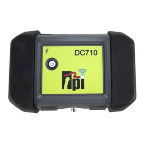
TPI DC710 User manual

DC710
Flue Gas Analyzer
The Value LeaderTM
www.tpi-thevalueleader.com

Contents
Introduction.................................................. 1
General Overview............................................... 1, 2
Instrument Overview........................................... 3 ~ 4
Front View............................................. 3
Back View............................................. 4
Basic Analyzer Functions...................................... 5 ~ 6
Turning The Analyzer On & Fuel Selection.. 5
Turning The Analyzer Off........................... 6
Combustion Analysis Overview.............................. 7
Combustion Analyzer Mode.................................. 7 ~ 14
Combustion Test Procedure....................... 7 ~ 14
Typical Test Locations.............................. 9 ~ 11
Typical Test Results................................ 14
Specifications................................................ 15 ~ 16
Calibration & Service....................................... 17
Warranty...................................................... 17
Appendix A General Maintenance & Function Tests........... 18 ~ 20
Appendix B A773 Sulfur Filter Installation & Maintenance. 21 ~ 22
Appendix C Field Sensor Replacement........................ 23 ~ 25
Appendix D Technical Notes..................................... 26
Appendix E Carbon Monoxide Facts............................ 27
Appendix F Carbon Monoxide Limits in Ambient Air Chart.. 28
Download the TPI View App
Download the TPI View app from the Apple®app store or the Google®
play store to begin using your DC710.

Introduction
Thank you for purchasing TPI brand products. The TPI DC710 com-
bustion analyzer is state of the art and easy to use. Connect it to your
smart device and you are ready to perform combustion analysis. The
instrument is ruggedly constructed and comes with a 3 Year unit and 2
Year sensor Guarantee.
Download the TPI View app from the Apple®app store or the Google®
play store to begin using your DC710.
General Overview
The TPI DC710 combustion analyzer uses field replaceable state of the
art electrochemical sensors. This sensor technology provides the
longest lasting most accurate and reliable means for performing com-
bustion tests. The sensors in your analyzer will need to be replaced
periodically and calibration is recommended once every year.
Electrochemical sensors by nature are always active. Therefore the
time the analyzer is off and not being used must be taken into account
when determining sensor life. The sensors in your analyzer are war-
ranted for two years. This warranty does not cover sensors damaged
through misuse of the analyzer.
You should keep the battery of your DC710 charged so power is con-
stantly being supplied to your sensors.
The following guidelines will help prevent damage to your sensors:
Always use the mini pump filter when testing flue gases.
Always periodically check and replace the mini pump filter as needed.
Always make sure the in-line filter / water trap is installed properly.
Always periodically check and replace the in-line filter as needed.
Always remove water or condensation from the inside of the in-line fil-
ter / water trap assembly prior to performing tests.
Always use the optional oil filter (p/n A773) when performing tests on
oil burning equipment.
1

General Overview (Continued)
Never over saturate your sensors by performing tests on equipment
with gas levels beyond the capability of you analyzer.
Always keep the A796 water trap / filter assembly clean and replace the
filter as necessary. Replacement filter part number is A762F.
This manual will guide you through the functions of the TPI DC710
which will give you many years of reliable service.
Your TPI DC710 Flue Gas Analyzer comes complete with the following
standard accessories:
• TPI DC710 Instrument
• Rubber Boot Ends
• Soft Carrying Case (A768)
• Flue Sampling Probe (A770)
• In-Line Filter assembly installed on Flue probe (A796)
• Temperature Probe (GK11M)
• Mini Pump Protection Filter Assembly and spare filters (A763)
• Exhaust Spigot (removable) (A764)
• Instruction Manual
( ) Denotes part number
Your TPI 717 Flue Gas Analyzer has the following options available:
• Spare In-Line Filter (A762F is a package of 5 filters)
• Field replaceable smart CO sensor (A760S)*
• Field replaceable smart O2 sensor (A761S)*
* Factory calibration once per year is recommended
2

Instrument Overview - Front View
Power Button Used to turn the DC710 on and off. Illuminates
green when power is on.
USB Charger Input Jack Connection for included charger.
Charge Indicator Red = Charging. Green = Fully charged.
Bluetooth Indicator Blue = Connected to smart device.
Red = Disconnected from device.
T1 Input Jack Connection for the flue probe temperature lead
(see page 8).
Gas Sampling Port Connection for Mini Pump Protection Filter and
Flue Probe (see page 8).
T2 Input Jack Connection for ambient tempreature probe. If
this probe isn’t used the DC710 uses it’s internal
temperature sensor (see page 8).
Rubber End Caps Protects the instrument from accidental damage
3
Charge
Indicator
Bluetooth
Indicator
Exhaust
Port
Rubber
End Cap
T1 Gas Sample T2
Input Port Input
Power
Button
USB Charger
Input Jack

Instrument Overview - Back View
Magnets: Used to attach the DC710 to a metallic surface for
hands free operation. Note: ensure to surface is not
hot or the DC710 may be damaged.
Hanging Hook: Used to attach hang the DC710 for hands free
operation.
Information Label: Contains the serial number and additional informa
tion regarding the DC710.
4
Information Label
Magnets Hanging Hook Magnets

BASIC ANALYZER FUNCTIONS
Analyzer Battery
Your combustion analyzer is fitted with a Lithium Ion rechargable battery. It is
important to keep battery power to the sensors in your analyzer even when it
is not in use. Your analyzer battery status is indicated at the top right corner
of the TPI View App. .
Turning The Analyzer On & Connecting to the App
Always: - Before turning on please ensure that nothing is connected to the
Gas Sample Port
Press and hold the power button until the power
switch lights on.
Start the TPI View App and tap the center icon to
begin scanning for TPI smart instruments.
A list of devices will be seen Select the DC710 to
connect to by tapping on the desired device.
Once connected the Bluetooth indicator on the
DC710 will turn blue and the app will display
measurement information.
After start up, several tests can be performed to
ensure proper function of the analyzer and flue
probe. Please refer to Appendix A.
5
'RZQORDGWKH73,9LHZDSS
IURPWKH$SSOHDSSVWRUHRU
WKH*RRJOHSOD\VWRUHWREHJLQ
XVLQJ\RXU'&

Turning The Analyzer Off
Always: - Before turning off return the instrument to a clean air environment
and allow the Carbon Monoxide level to return to below 10ppm and the
Oxygen level to return to 20.9% (± 0.5%)
If the pump is running tap “Stop Pump” to turn
the pump off. If the CO is above 10ppm or the
O2 is below 19% the Stop Pump icon will be
grreyed out. Once the O2 and CO levels are
within necessary limits the Stop Pump icon will
be active.
Once the pump is off close the app or discon-
nect from the DC710. Press and hold the power
key on the DC710 to turn the analyzer off.
If the app is disconnected before the CO is
below 10ppm or the O2 is above 19% and the
power key is held down to turn the analyzer off,
the pump will continue to run until the CO and
O2 are within limits. Once within limits the
DC710 will auto power down.
6

COMBUSTION ANALYSIS OVERVIEW
Performing combustion analysis is very important to the overall safety and
efficiency of heating equipment. The following guidelines and descriptions are
generic and meant to provide you with a basic understanding of combustion
testing. TPI always recommends you contact the manufacturer of the device
under test, obtain information specific to the device, and follow the proce-
dures and safety guidelines for performing tests and affecting repairs.
In general, for most applications, flue gas samples should be taken prior to
the draft diverter or any other opening that allows room air to enter the sys-
tem. This prevents room air from mixing with gases in the flue and diluting
the test sample. To ensure accurate and consistent combustion tests, it is
important gas and temperature samples be taken at the same location. This is
easy with the TPI flue probe because the temperature sensor is an integral
part of the probe.
Prior to taking a sample, the device under test should be on and operating.
Putting the flue probe in the sample area prior to starting the device may
cause saturation of the sensors due to the higher initial concentration of car-
bon monoxide that may be encountered upon start up. If this happens, allow
your analyzer to purge in fresh air until the carbon monoxide level returns to
0 ppm and the oxygen level returns to 20.9%. This may take more than an
hour depending on how saturated the sensors are.
The figures on pages 10 through 12 show locations for performing tests on
commonly encountered equipment. Remember to consult with the manufac-
turer of the device under test for specific test information.
Refer to the Appendix D “Technical Notes” for additional information.
7

Combustion Test Procedure
Note: It is recommended you perform routine general maintenance on your
analyzer to ensure proper function. Please refer to Appendix A for general
maintenance schedule and function tests.
1. Turn the DC710 on and connect it to the TPI
View app as outlined on page 5. Make sure you
are in a “clean air” environment (no CO) and tap
“Start Pump”.
2. Connect the Mini Pump Protection
Filter assembly and Flue Probe Tubing
complete with In-Line Filter to the Gas
Sample Port and the 'K' Type
Thermocouple Plug from the Flue
Probe into Thermocouple (T1)
Socket.
The GK11M ambient air temperature
probe is connected to the (T2) socket.
If this probe is not used the analyzer
will use it’s internal temperature sen-
sor for ambient air (T2) reference.
WARNING: - Ensure the 'K' type ther-
mocouple probes are inserted into the
sockets correctly. The plugs are
polarity marked and forcing the plug
into the socket the wrong way may
result in damage to the instrument.
8

IMPORTANT: Prior to taking a sample, the device under test should be on and
at operating temperature. Putting the flue probe in the sample area prior to
starting the device may cause saturation of the sensors due to the higher
initial concentration of carbon monoxide that may be encountered upon
start up. If this happens, allow your analyzer to purge in fresh air until the
carbon monoxide level returns to 0 ppm and the oxygen level returns to
20.9%. This may take more than an hour depending on how saturated the
sensors are.
3. Drill a 1/4 inch hole into the flue of the device under test. For most applica-
tions, flue gas samples should be taken prior to the draft diverter or any
other opening that allows room air to enter the system. This prevents room
air from mixing with gases in the flue and diluting the test sample.
It is important to use manufacturers recommended test locations whenever
possible.
Refer to the figure below for calculating the sample hole location.
The figures on the following pages show typical test locations on commonly
encountered equipment.
9

TYPICAL TEST LOCATIONS
Atmospheric Gas Fired Fan Assist Boiler / Furnace
Typical Test Locations
Figure 1
It is important to use manufacturers recommended test locations
whenever possible.
10

TYPICAL TEST LOCATIONS
Condensing Boiler / Furnace
Typical Test Locations
Figure 2
It is important to use manufacturers recommended test locations
whenever possible.
11

Test all exhaust ports at the
top of the heat exchanger.
Atmospheric Forced Air Furnace
Typical Test Locations
Figure 3
TYPICAL TEST LOCATIONS
It is important to use manufacturers recommended test locations
whenever possible.
12
Carbon Monoxide

4. Insert the flue probe into the sample hole of the device under test. The
probe tip should be in the middle of the flue pipe or exhaust stream.
Ensure the In-Line Filter / Water Trap hangs below the analyzer in the proper
vertical position when readings are being taken. Failure to comply reduces
the effectiveness of the water trap and may result in damage to the instru-
ment. Refer to the pictures below for correct and incorrect use.
WARNING: - Should the CO reading rise above 2,000ppm the probe should
immediately be disconnected from the instrument and the instrument
returned to a clean air environment. This ensures the analyzer will not be
subjected to an abnormally high concentration of CO, and will protect the
sensors.
Make sure to check the water trap periodically during testing to ensure it
does not fill with condensate and empty it as necessary. If the filter begins to
fill during a test, open the lid and empty out the condensate. After closing the
lid, allow readings to stabilize again.
IMPORTANT: The water trap is fitted with a water block filter (p/n A794W) in
the lid to prevent water from flowing down into the pump. If the water trap
fills the water block filter will stop the flow to the analyzer and the pump will
slow and no longer pull a sample. The water trap should be emptied immedi-
ately if this happens. The water block filter may need to be dried out
or replaced before testing can resume. 13

5. The combustion analysis readings will be displayed on the TPI View app.
Allow the readings to stabilize.
The date, time, battery status, last
calibration date, and calibration due
date are displayed at the top.
The fuel type is selectable by tapping
on the down arrow next to the
diplayed fuel.
Parameter Displayed:
CO Level (measured)
CO2 percentage (calculated)
CO Air Free (calculated)
O2 Level (measured)
Excess Air (calculated)
T1 Temperature (flue temp mea-
sured)
Internal Temperature (ambient air
measured) or T2 Temperature (mea-
sured) if the ambient air probe is
connected to T2
Temperature Difference (T1-Ambient)
Efficiency (Calculated)
The efficiency type can be set to Net
or Gross by tapping on the down
arrow key.
Note: Gross efficiency is used in the
USA.
14

6. A report of the test results can be generated and sent via email or printed
to the optional A740BT Bluetooth printer.
Tap “Create Report” to start the
report generation process.
A box will pop up asking you to
enter a report reference. This is like
the job name or number of the
report.
Once you have entered the desired
reference name tap “Set”
From the report screen you can edit
the reference name, email the report
to a recipient, and print the report to
the optional A740BT Bluetooth print-
er.
15

16
TYPICAL TEST RESULTS
Oxygen 3% to 6%
Carbon Monoxide Less than 100ppm (air free)
Stack Temperature 300°F to 500°F
Draft -0.15 inH2O
Oxygen 4% to 7%
Carbon Monoxide Less than 100ppm (air free)
Stack Temperature 325°F to 625°F
Draft -0.15 inH2O
Power Burners (Gas Fired)
Power Burners (Oil Fired)
Oxygen 7% to 9%
Carbon Monoxide Less than 100ppm (air free)
Stack Temperature 325°F to 500°F
Draft -0.15 inH2O to -0.4 inH2O
Gas Fired Burners (Atmospheric / Fan Assist)

SPECIFICATIONS
Instrument
Operating Temperature Range
Battery Type
14°F to 122°F (-10°C to 50°C)
Rechargeable Li-ion (3.7V/2600mA)
Battery Life >6 hours typical
Charger Port USB Connection
Pre-Programmed Fuels Natural Gas, LPG, Light Oil, Heavy Oil,
Bituminous Coal, Coke, Butane, Wood,
Bagasse
Dimensions 150mm x 100mm x 58mm
Weight 490g
Gas Sensor Type Electrochemical field replaceable smart
sensors (O2 and CO)
Flue Temperature Probe
Construction Pistol Grip with Stainless Steel Shaft
Hose Length 2500mm
Insertion Length 200mm
'K' Type Thermocouple Accuracy +/- 0.3%, +/- 2°F (1°C)
Maximum Temperature 1472°F (800°C)
Gases
Range Resolution Accuracy
Oxygen 0-25% 0.1% +/- 0.3%
Carbon Monoxide 0-10,000 ppm 1 ppm +/- 5 ppm or 5%
Whichever is greater
Carbon Dioxide 0-25% 0.1% Calculated
CO/CO2 Ratio 0-0.999 0.001 Calculated
Combustion Efficiency 0-100% 0.1% Calculated
17

SPECIFICATIONS (Continued)
Temperature Measurement
Input Type K-Type thermocouple
Range -58°F to 1832°F (-50°C to 1000°C)*
Resolution 1°F (1°C)
Accuracy +/- (0.3% of rdg + 2°F) or +/- (0.3% of rdg + 1°C)
* The thermocouple supplied (GK11M) has the ability to measure tempera-
tures in the -50°F to 950°F range. The DC710 accepts industry standard K-
type thermocouple probes with sub-mini connectors.
Blutooth Communication
Bluetooth Version: 4.2
FCC ID: QOQBGM111
IC: 5123A-BGM111
: 209-J00192
18
Other manuals for DC710
1
Table of contents
Other TPI Measuring Instrument manuals
Popular Measuring Instrument manuals by other brands
Satec
Satec PM172 Series reference guide
Konica Minolta
Konica Minolta AeroDR System Operation manual
Tecnologic
Tecnologic TRH 12 manual
BURG WATCHER
BURG WATCHER ProfiScale CROSS operating instructions
MindWare Technologies
MindWare Technologies MindWare Mobile product manual
ThermoWorks
ThermoWorks TW-USB-1 Installation and operation guide
