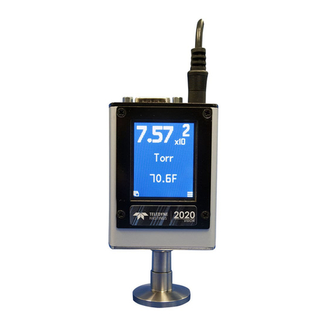
200/202 Series Flowmeters and Controllers Instruction Manual
EAR99 Technology Subject to Restrictions Contained on the Cover Page Page 3 of 27
Table of Contents
1. GENERAL INFORMATION .................................................................................................. 5
FEATURES................................................................................................................ 6
SPECIFICATIONS HFM-200*.............................................................................................. 7
SPECIFICATIONS HFC-202*.............................................................................................. 8
OPTIONAL 4-20 MACURRENT OUTPUT................................................................................... 9
ACCESSORIES............................................................................................................ 10
1.5.1. Power Supplies................................................................................................ 10
1.5.2. Cables .......................................................................................................... 10
2. INSTALLATION AND SETUP ..............................................................................................11
RECEIVING INSPECTION .................................................................................................. 11
POWER REQUIREMENTS.................................................................................................. 11
2.2.1. ±15 VDC Option ............................................................................................... 11
2.2.2. 24 VDC Option ................................................................................................ 11
OUTPUT SIGNAL ........................................................................................................ 12
MECHANICAL CONNECTIONS ............................................................................................. 12
2.4.1. Mounting....................................................................................................... 12
2.4.2. Gas Quality .................................................................................................... 12
2.4.3. Upstream & Differential Pressure ......................................................................... 12
2.4.4. Other Mounting & Fitting Options, Notes ................................................................ 12
2.4.5. Laminar Flow Element (LFE) Configuration.............................................................. 13
ELECTRICAL CONNECTIONS .............................................................................................. 14
2.5.1. Bipolar (±15 VDC) Power Supply to Bipolar Connections .............................................. 14
2.5.2. Unipolar (24 VDC) Power Supply to Unipolar Connections ............................................ 15
2.5.3. General Connection Notes .................................................................................. 15
OPERATION ............................................................................................................. 16
2.6.1. Operating Conditions ........................................................................................ 16
2.6.2. Zero Check..................................................................................................... 16
2.6.3. High Pressure / High Density Option...................................................................... 16
2.6.4. Gas Blending .................................................................................................. 17
OPERATION WITH EXTERNAL DEVICES.................................................................................... 17
2.7.1. Operation with a Hastings Power Supply................................................................. 17
2.7.2. Operation with a Non-Hastings Power Supply ........................................................... 18
2.7.3. Operation with an External Sensor (External Input) ................................................... 19
2.7.3.1. 15 Volt Units............................................................................................................ 19
2.7.3.2. 24 Volt Units............................................................................................................ 19
2.7.4. Response to Command Changes............................................................................ 20
RANGE CHANGING ...................................................................................................... 20
