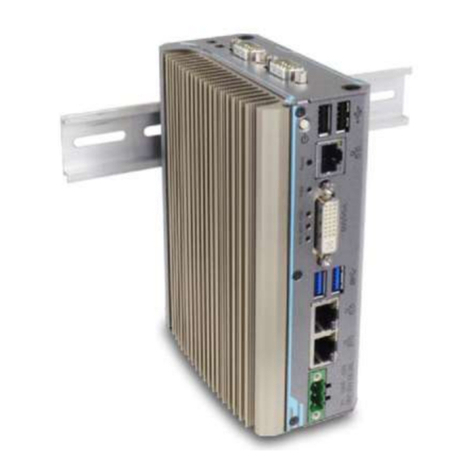
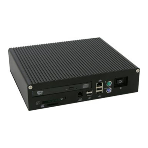
Acnodes FES2215 User manual

FES2215
Fanless Embedded System
User Manual
FES2215:FanlessEmbeddedSystemAtomD2550
DualCore1.86GHzProcessor
14628 Central Ave,
Chino, CA 91710
tel:909.597.7588, fax:909.597.1939
© Copyright 2013 Acnodes, Inc.
All rights reserved. Product description and product specifications
are subject to change without notice. For latest product information,
please visit Acnodes’web site at www.acnodes.com.


Copyright
This publication contains information that is protected by copyright. No part of it may be reproduced in
any form or by any means or used to make any transformation/adaptation without the prior written
permission from the copyright holders. The manufacturer reserves the right to revise this publication and
make changes to its contents at any time, without obligation to notify any person or entity of such
revisions or changes.
©2013. All Rights Reserved.
Trademarks
All trademarks and registered trademarks of products appearing in this manual are the properties of their
respective holders.
Notice:
1. The changes or modifications not expressly approved by the party responsible for compliance could void the user’s authority
to operate the equipment.
2. Shielded interface cables must be used in order to comply with the emission limits.
Static Electricity Precautions
It is quite easy to inadvertently damage the system board, components or devices even before installing
them in your system unit. Static electrical discharge can damage computer components without causing
any signs of physical damage. You must take extra care in handling them to ensure against electrostatic
build up.
1. To prevent electrostatic build up, leave the system board in its anti-static bag until you are ready to install
it.
2. Wear an antistatic wrist strap.
3. Do all preparation work on a static-free surface.
4. Hold the device only by its edges. Be careful not to touch any of the components, contacts or
connections.
5. Avoid touching the pins or contacting all modules and connectors. Hold modules or connectors by their
ends.
Important:
Elect rost atic d ischa rge (ESD) can damage you r p rocessor, disk dr ive an d ot her compo nents. Perform t he up grade instru ct ion
pr ocedures describ ed at an ESD wor kstation on ly. If such a sta tion is no t availab le, yo u can provide some ESD protection by
wear in g a n ant istatic wrist st rap and attaching it to a met al part of the system chassis. If a wr ist strap is unavailab le, es tab lish
and maintain contact with the system chassis throughout any procedures requiring ESD protection.

FES2215
Fanless Embedded System
Safety Measures
To avoid damage to the system:
• Use the correct AC input voltage range to reduce the risk of electric shock.
• Unplug the power cord before removing the system chassis cover for installation or servicing. After
installation or servicing, cover the system chassis before plugging the power cord.
Battery:
• Danger of explosion if battery incorrectly replaced.
• Replace only with the same or equivalent type recommend by the manufacturer.
• Dispose of used batteries according to local ordinance.
Warranty
1. Warranty does not cover damages or failures caused by misuse of the product, inability to use the
product, unauthorized replacement or any kind of alterations of components and product
specifications.
2. The warranty is voided if the product has been exposed to physical abuse, improper installation, any
kind of modification, accidents or unauthorized repair of the product.
3. Unless otherwise instructed in this user manual, the user may not, under any circumstances, attempt to
perform service, adjustments or repairs on the product himself, whether the product is still covered by
warranty or not. It must be returned to the place it was purchased at, the factory or an authorized
service agency for any repair work.
4. We will not be liable for any indirect, special, incidental or consequent damages to the product that has
been modified or altered.
14628 Central Ave,
Chino, CA 91710
tel:909.597.7588, fax:909.597.1939
© Copyright 2013 Acnodes, Inc.
All rights reserved. Product description and product specifications
are subject to change without notice. For latest product information,
please visit Acnodes’web site at www.acnodes.com.
FES2215
Fanless Embedded System
Table of Contents
Copyright .................................................................................................................. 2
Trademarks ............................................................................................................... 2
Static Electricity Precautions .................................................................................... 2
Safety Measures ....................................................................................................... 3
Warranty ................................................................................................................... 3
Chapter 1: Introduction
1-1 Overview.............................................................................................................. 5
1-2 Product Specification........................................................................................... 6
1-3 System Block Diagram......................................................................................... 8
1-4 Mechanical Diagram........................................................................................... 9
1-5 Front and Rear I/O…............................................................................................ 10
Chapter 2: Pin Definition & Jumper Settings
2-1 Front panel Pin Definition…………………………………………………….............…………… 11
2-2 Rear Panel Pin Definition……………………… …………………………………………… …………. 11
2-3 Internal Pin Definition & Jumper Settings………………………………… ……………………. 14
2-3.1 Main Board Top V iew………………….………………………………………………………. 14
2-3.2 Main Board Pin Definition…………….…………………………………………… …………. 15
2-3.3 Jumper Setting…………………………….………………………………………………………. 16
Chapter 3: UEFI Setup Utility
3-1 Introduction……………………….……………………………………………… …………………………. 23
3-2 Main Screen…………………………………………………………………………………….…………… 24
3-3 Advanced Screen……… ……………………………………………… …………………………….…… 25
3-4 Hardware Health Event Monitoring Screen..……………………………………… .………… 33
3-5 Boot Screen...………………………………………………………………………………………………… 34
3-6 Security Screen………………………………………………………………………………………………35
3-7 Exit Screen…………………………………….……… ………………………………………………………36
Chapter 4: Installation Guide
4-1 Memory Modules (SO-DIMM).………………………………… ……………………………………. 37
4-2 Expansion Slot (PCI Slot)……………………………………………………… ………………………… 38
14628 Central Ave,
Chino, CA 91710
tel:909.597.7588, fax:909.597.1939
© Copyright 2013 Acnodes, Inc.
All rights reserved. Product description and product specificati ons
are subject to change without notice. For latest product information,
please visit Acnodes’web site at www.acnodes.com.
FES2215
Fanless Embedded System
Chapter 1:
I
n
t
r
odu
c
t
i
on
1-1 Overview
Acnodes’FES 2215 is anoutstandingand reliableFan-lessembedded system with high
performanceand low power consumption remained.
Thenew FES2215 provides customer achoiceof Atom D2550 / N2800 / N2600 Processor,dependson
themodel beingselected. FES2215has applied by therecent launched Atom™Processor D2550 Dual-
core1.86GHz Processor, which deliveries enhanced performancein multi-media capability on the
market at thepresent moment and it offersto reachthemaximum memory size up to 4 GBDDR3-
800/ 1066 whileasthegraphic clock speed of 640MHz. FES2215 supportsfor dual display of VGAand
HDMI.Furthermore, whileasthenew FES2215 isequipped of NM10 South BridgeChipset, which
deliverieshigh speed storageinterfacethat supportsfor faster datatransferringrate asto increase
efficiency
In order to meet thenetwork stability,theFES2215 series usetwo Realtek 81xx100/ 1000 Mbps LAN
with Wake-On LAN &DMI to support and maintain Ethernet function. Thesystem designed with two
DB-9; onesupports for RS-232/ 422/ 485 and onesupports for RS-232 interface, and one RJ-45
supports for RS-232. Thereare threeof DB-9 for RS-232 reserved for optional expansion availability.
Asoftwareprogramming Watchdog(WDT) with timer rangefrom 1to 255 seconds is enabled in Pipal
2215. For theaudio output,therehas occupied with an ALC662 for speaker.
The power supply is capable for DCpower input of 12V or 24V.The power consumption is able to
reach up to 22W in maximum. The system is valuable for all the embedded applications, and also
well support with theWindow 7,WindowsXP and Linux Operation system.
The new FES2215 is not only capable and reliable to offer you an unprecedented experience with
extremely high graphic performance along with remaining low on power consumption but also
present an outstandingcost-competitiveadvantagein themarket.
14628 Central Ave,
Chino, CA 91710
tel:909.597.7588, fax:909.597.1939
© Copyright 2013 Acnodes, Inc.
All rights reserved. Product description and product specifications
are subject to change without notice. For latest product information,
please visit Acnodes’web site at www.acnodes.com.
1-2
P
r
odu
c
t
S
p
eci
f
ica
t
i
on
Processor&
C
h
i
ps
e
t
Support Atom D2550 Dual-core 1.86 GHz low power Processor
NM10 South Bridge Chipset
Graphic
E
ngine
Graphic core 640 Mhz
Support AVC/ H.264, VC1/ WMV9, MPEG2 HW engine
Blu-Ray Support
HDCP 1.3ans PAVP 1.1C content protection support
Support Microsoft DXVA 2.0 and Overlay DD
MS COPP and PVP-OPM support
Enabling Key ISVs-Corel, CyberLink, ArcSoft
Supports OpenGL 3.0 and Microsoft DirectX 9
S
ys
t
e
m
Mem
ory
2 SODIMM Socket, up to 4 GB 800/ 1066 MHz DDR3 Memory
Display
Fun
c
t
i
on
Support VGA + HDMI dual display
HDMI, VGA support 1920 x 1200 (1080P) resolution
B
I
OS
AMI BIOS. Support Power On After Power failure
Expansion
1 Mini-PCI-E
expansio
n slot
Note: may install mSATA SSD, Wireless LAN
module
Audio
ALC 662 HD Codex support, 2W amplifier for Speaker out
Ethernet
2 Realtek 81xx 100/1000 Mbps LAN with Wake-On-LAN& DMI
Disk Drive
S
t
o
r
a
g
e
2.5” SATA HDD & 1 Mini-PCI-E mSATA (share Mini-PCI-E slot)
RS -
232
/
422
/
485
S
uppo
r
t
Default: 2 DB-9 as 1 for RS-232/422/485 & 1 for RS-232, 1RJ-45 for RS-232
Optional Expansion: 3 DB-9 for RS-232
W
a
t
c
hdog
Timer
Programmable WDT from 1 to 255 seconds/ minutes
Power
On/Off
Mode
Push button AT/ATX power on/ off
RTC Alarm Power on

F
r
on
t
Panel Extend
I
/
O
P
o
r
t
s
Power & HDD Led. Power & System, Power & Reset button
Rear Panel
E
xtend
I
/
O
P
o
r
t
s
Screw-Lock DC power input connector
2 DB-9 as 1 for RS-232/422/485 & 1 for RS-232, 1 RJ-45 for RS-232
VGA + HDMI display interface
4 USB , 2 RJ-45 100/1000 Mbit LAN connector
1 Microphone-in, 1 Line-out connector
1 PS/2 Keyboard and 1 PC/2 Mouse connector
Rear Panel
O
p
t
i
on
al
I
/
O
3 DB-9 for COM 4, 5, 6 RS-232 port or 2 COM + 1 Digital I/O
1 DB-25 for Printer port
Power
S
uppl
y
DC 12V or 24V input. 12VFC/ 2.5A, 24VDC/1.25A, AT/ATX power type
Power adapter : AC to DC , DC 12V/5A 60W ( Optional )
Power
Consum
p
t
i
on
(with
HDD )
Typical Power Con
sumption
: 17W
Maximum Power Consumption: 22W
E
nv
i
r
on
m
e
n
t
Operation Temperature:
- With extend temperature HDD:
-20°C~60°C
- With extend temperature SSD:
-20°C~60°C
Storage Temperature: -40°C~85°C
Relative Humidity: 10%~90% (Non-condensing)
Mechanical
Dimension W x H x D : 200 mm x 89.83 mm x 185.5mm (7.87'' x 5.34'' x 7.30')'
Mounting: Desk/Wall Mount
Construction: Aluminum housing
Weight (Net/ Gross): 4.4KG (9.68lb)/ 5.0KG (10.4lb)
Certification
CE/FCC Class A
OS S
uppo
r
t
s
Windows 7, Win XP, Linux

1-3
S
ys
t
e
m
Block Diagram
FES
2215

1-4 Mechanical Diagrams
FES
2215

1-5
F
r
on
t
& Rear panel
F
r
on
t
Panel
Rear Panel

2-1
F
r
on
t
panel Pin Definition
1. Power On/ Off Button
2. Power Reset Button
3. Power & HDD LED
2-2 Rear Panel Pin Definition

2. COM 1 (DB-9): RS-232/ 422/ 485 [refer to P.17-18, No. 8 jumper setting]
PIN
RS-232
RS-422
RS-486
1
DCD#
TX+
RTX+
2
RXD
RX+
Not Used
3
TXD
TX-
RTX-
4
DTR#
RX-
Not Used
5
GND
GND
GND
6
DSR#
Not Used
Not Used
7
RTS#
Not Used
Not Used
8
CTS#
Not Used
Not Used
9
RI#
Not Used
Not Used
4 & 5. LAN 1 & 2 (RJ-45)
PIN
Definition
PIN
Definition
1
Lan_TX1+
2
Lan_TX1-
3
Lan_TX2+
4
Lan_TX3+
5
Lan_TX3-
6
Lan_TX2-
7
Lan_TX4+
8
Lan_TX4-
6. Line-Out Connector
PIN
Definition
PIN
Definition
1
LINE_OU T_Left
2
LINE_OUT_Right
3
AUDIO_AGND
4
AUDIO_AGND
5
LINE_IN_Left
6
LINE_IN_R ight
7
AUDIO_AGND
8
AUDIO_AGND
9
Micro phone_IN1
10
Micro phone _IN2
8 & 9. USB Connector [refer to P.17, No. 10 jumper setting]
PIN
Signal
PIN
Signal
1
5V
5
5V
2
D-
6
D-
3
D+
7
D+
4
GND
8
GND
11. COM 3 (RJ-45): RS-232 [refer to P.21, No. 22 jumper setting]
12. COM 2 (DB-9): RS-232
Pin
Definition
Pin
Definition
1
DCD
2
RX
3
TX
4
DTR
5
GND
6
DSR
7
RTS
8
CTS
9
RI

2-3
I
n
t
e
r
n
al
Pin Definition & Jumper Settings
2
-
3.1
Main Board Top View

2
-
3
.
2
M
ain Board
P
in
D
e
f
i
n
i
t
i
on

2
-
3.3
Jumper Settings
1. Clear CMONS Jumper (CLRCMOS1) [refer to P.13, No. 16]
It allows you to clear the data in CMOS. To clear and reset the system parameters to default
setup, please turn off the computer and unplug the power cord from the power supply. After
waiting for 15 seconds, use a jumper cap to short pin 2 and pin 3 on CLRCMOS1 for 5 seconds.
However, please do not clear the CMOS right after you update the BIOS. If you need to clear the
CMOS when you just finish updating the BIOS, you must boot up the system first, and then shut it
down before you do the clear-CMOS action. Please be noted that the password, date, time, user
default profile and MAC address will be cleared only if the CMOS battery is removed.
2. Digital I/O Header PWR Setting (3-pin JGPIO_PWR1) [refer to P.13, No.14]
3. PWR-On Mode Setting (3-pin PWR_JP1) [refer to P.13, No.17]
4. Panel VDD PWR Setting (3-pin PNL_PWR1) [refer to P.13, No.26]
5. Panel BackLight PWR Setting (3-pin BKT_PWR1) [refer to P.13, No. 27]

7. Panel Resolution Selection (12-pin JLVD_GPIO1) [refer to P.13, No. 29]
8. SET COM Ports
(10-pin SET_CM1,2) [refer to P.13, No. 1]
(10-pin SET_CM4,5,6) [refer to P.13, No. 20]
(5-pin SET_CM3) [refer to P.13, No. 30]

(COM 1 Pin1 & Pin 9 Function Setting)
Item
Pin 1 Function
Connector SET_COM1 Jumper Setting
Config. 1
Provide +12V Power Source
Pin 1 & Pin 3 short, Pin 5 & 7 & 9 NC
Config. 2
Provide +5V Power Source
Pin 3 & Pin 5 short, Pin 1 & 3 & 9 NC
Config. 3
Provide DCD# Function
Pin 7 & Pin 9 short, Pin 1 & 3 & 5 NC
Item
Pin 9 Function
Connector SET_COM1 Jumper Setting
Config. 1
Provide +12V Power Source
Pin 2 & Pin 4 short, Pin 6 & 8 & 10 NC
Config. 2
Provide +5V Power Source
Pin 4 & Pin 6 short, Pin 2 & 4 & 10 NC
Config. 3
Provide RI# Function
Pin 8 & Pin 10 short, Pin 2 & 4 & 6 NC
9. SATA 2 Connectors (SATA2_1) [refer to P.13, No. 8]
(SATA2_2) [refer to P.13, No. 10]

10. USB 2.0 Ports
(4-pin USB 4,5) [refer to P.13, No. 11]
(4-pin USB6) [refer to P.13, No. 12]
11. System Panel Header (9-pin PANEL 1) [refer to P. 13, No. 15]
Connect the power switch, reset switch and system status indicator on the chassis to this
header according to the pin assignments below. Note the positive and negative pins before
connecting the cables.
- PWRBTN (Power Switch)
- RESET (Reset Switch)
- PLED (System Power LED)
- HDLED (Hard Drive Activity LED)

13. Front Panel Audio Header (9-pin HD_AUDIO1) [refer to P.13, No. 25]
14. DC 12V Power Connector (4-pin DC 12V1) [refer to P.13, No. 3]
15. COM Port 4,5,6 (10-pin COM 4,5,6) [refer to P. 13, No. 19]

16. Print Port Header (25-pin LPT1) [refer to P.13, No. 9]
17. LVDS Con (40-pin LVDS1) [refer to P.13, No. 2]
18. Output Power (4-pin SATA_PWR1) [refer to P.13, No. 7]
Table of contents
Other Acnodes Desktop manuals

Acnodes
Acnodes RMC8416 User manual

Acnodes
Acnodes FPC 8121 User manual

Acnodes
Acnodes LW 922 User manual

Acnodes
Acnodes FES 8000 User manual

Acnodes
Acnodes PLW 8150 User manual

Acnodes
Acnodes RMC 8310A User manual

Acnodes
Acnodes LW 910 User manual

Acnodes
Acnodes RMC 3072A User manual

Acnodes
Acnodes RMC 7212A User manual

Acnodes
Acnodes RMC 6015A User manual

Acnodes
Acnodes FES 9000 User manual

Acnodes
Acnodes RMC 6224A User manual

Acnodes
Acnodes RMC 6125A User manual

Acnodes
Acnodes LW 846 User manual

Acnodes
Acnodes RMC 6343A User manual

Acnodes
Acnodes RMC 6220B User manual

Acnodes
Acnodes RMC 6220A User manual

Acnodes
Acnodes LW 846 User manual

Acnodes
Acnodes FPC-8057 User manual

Acnodes
Acnodes RMC 7217A User manual