Acnodes RMC8416 User manual

2
INSTALLATIONSTEPS
To install the RMC 8416 chassis, the following installation
steps must be completed:
Step 1: Unpack the chassis.
Step 2: Install the front handles.
Step 3: Remove the top cover and hold-down clamp.
Step 4: Install the PSU.
Step 5: Install the backplane.
Step 6: Install the CPU card.
Step 7: Install the PCI and ISAexpansion cards.
Step 8: Install the disk drives.
Step 9: Connect front panel cables.
Step 10: Connect PSU cable and interface cable.
Step 11: Install the hold-down clamp and PCI/ISA
card shock absorbers.
Step 12: Reinstall the top cover.
The installation steps outlinedabove are described in
detail below. Please refer to the relevant section.
STEP 1: UNPACK
The RMC 8416 is shipped in a plastic bag that is placed
inside acardboard box. The items are also shipped with
the chassis. When you unpack the chassis you must:
Make sure all the items listed above are present.
Make sure the chassis has not been damaged in any
way.
STEP2:FRONT HANDLEINSTALLATION
Two handles are shipped with the RMC 8416 chassis. The
handles are installed on the sides, at the front of the
chassis. Each handle is secured to the chassis by 4
retention screws. To install the handles, please follow the
steps below:
Step 1: Align the retention screw holes on the side of the chas-
sis with the retention screws in the handle.
Step 2: Insert 4 retention screws for each handle.
Figure 2: Insert 4 Front Handle Retention Screws
STEP3: TOP COVERAND HOLD-DOWN CLAMPREMOVAL
3.1:TOPCOVERREMOVAL
The top cover is secured to the chassis with 6 retention screws,
three on each side of the chassis. To remove the top cover, please
follow the steps below:
Step 1: Remove all 6 top cover retention screws. Remove 3
retention screws from each side of the chassis.
Figure3:TopCoverRetentionScrews
Step 2: Slide the top cover backwards and Lift the top cover up
gently.

3
STEP 3.2: HOLD-DOWN CLAMPREMOVAL
Detach the hold-down clamp byremoving the 2 screws located on each side of the chassis and lift the hold-down clamp off
the chassis.
Figure 5: Remove the2Hold-Down Clamp Retention Screws
Figure 6: Lift the Hold-Down Clamp off the Hold-Down
ClampSecuringHook
STEP 4: Install the Power Supply Unit (PSU)
Once the top cover and hold-down clamp have been removed, the PSU must be installed. Compatible IEI PSUs are listed in
the table below.
Table 2: Compatible IEI PSUs.

15-inch touch panel PC
4
The PSU is installed at the rear of the chassis. The PSU
is secured to the chassis with an internal PSU securing
clamp and 4 retention screws from the rear of the chassis.
To install the PSU, please follow the steps below:
Step 1: To remove the PSU securing clamp, remove the
2 PSU securingclamp retention screws.
Figure 7: PSU Securing Clamp Retention Screws
Step 2: Correctly position the PSU at the rear of the
chassis making sure that the power switch and the cable
socket both face outwards.
Step 3: Once the PSU has been correctly positioned,
secure the PSU to the chassis by inserting 4 retention
screws through the rear of the chassis.
Figure 8: Insert PSU Retention Screws
Step 4: Reinstall the PSU securing clamp and
reinsert the 2 previously removed PSU securing
clamp retention screws.
STEP5:BACKPLANEINSTALLATION
The IEI backplanes listedbelow are compatible with the
RMC 8416 chassis.
Table3:CompatibleBackplanes
To install a compatible backplane please follow the
instructionsbelow:
Step 1: Insert the copper pillars in the predrilled screw
holes in the bottom of the chassis according to the
distribution of the retentionscrew holes in the backplane
you want to install.
Figure9: Locations of the 9 Copper Pillars
Step 2: Mount the backplane onto the copper pillars and
align the backplane screwholes with the screw holes in
the copper pillars.

5
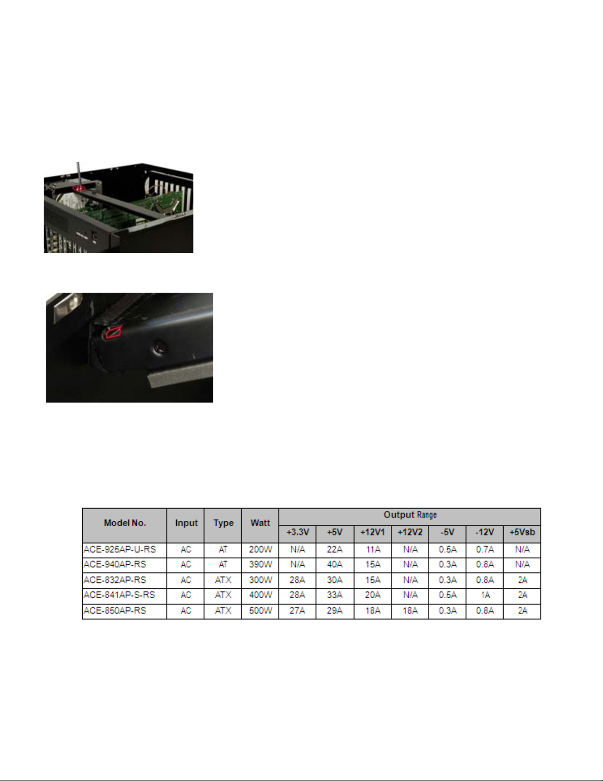
Step 3: Once the backplane is properlyaligned with the
retention screw holes, insert retention screws in all the
retention screwholes in the backplane to secure the
backplane to the chassis.
Figure10: InsertBackplaneRetentionScrews
STEP6:CPUCARDINSTALLATION
To install the CPU card please follow the instructions
below:
Step 1: Remove the slot cover at the front of the chassis.
To do this, remove the slot cover retention screwat the top
of the slot cover.
Figure 11: Remove the SlotCover Retention Screw
Step 2: Slide the CPU card into the socket on the
backplane reserved for the CPUcard. If you are installinga
full-size CPU card, make sure the back edge of the CPU
card slots into the corresponding plastic guides located
behindthe coolingfans.
Step 3: To secure the CPU card, reinsert the previously
removedslotcoverretentionscrew.
STEP 7: PCI/ISAEXPANSION CARD INSTALLATION
The RMC8416 supports upto13 PCI/ISAexpansion
cards. To install an expansion card (PCI or ISA) please
follow the steps below.
Step 1: Remove the slot cover at the back of the chas-
sis. To do this, remove the slot cover retention screw at
the top of the slot cover.
Step 2: Slide the PCI/ISAexpansion card into reserved
PCI/ISA socket on the backplane.
Step 3: To secure the PCI/ISA expansion card,
reinsert the previouslyremoved slot coverretentionscrew.
STEP 8: DISK DRIVES INSTALLATION
The RMC 8416 chassis has 2 drive brackets: a main drive
bracket and a side bracket. To installthe drives, please
follow the steps outlined in the sections below.
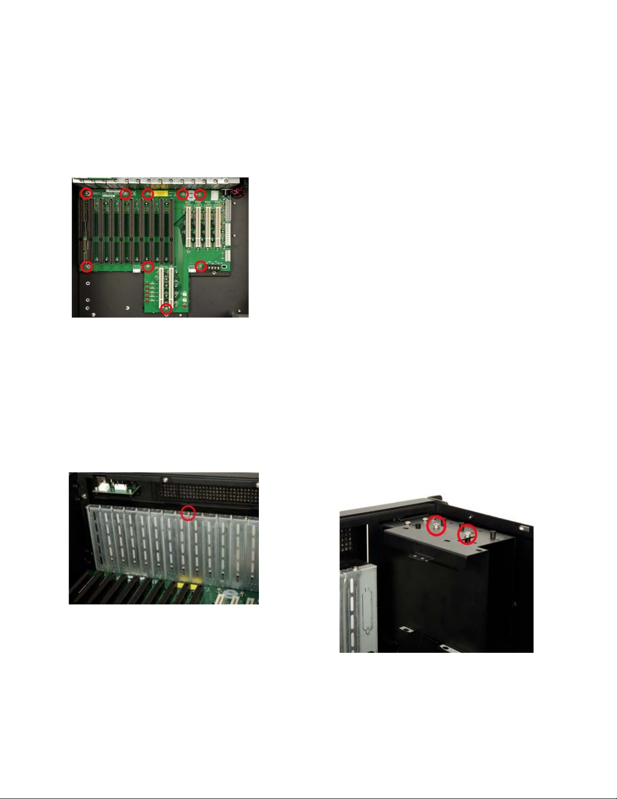
STEP8.1:REMOVETHESIDEBRACKET
Before anydrives can be installed, the side bracket
attached to the maindrive bracket must be removed.To
remove the side bracket,removethe2 retention screws
from the top of the side bracket that secure the side
bracket to the main bracket.
Figure12:RemovetheSideBracket

6
STEP 8.2: 3.5" DRIVE INSTALLATION INTO THE
SIDEBRACKET
The side bracket supports one 3.5" drive. If you want to
install a 3.5" drive into the side bracket, please follow the
steps below:
Step 1: Place a 3.5" FDD drive into the bracket. Make
sure the FDD PCB board is facing the surface of the
bracket and the 4-pin power connector and the IDE/SATA
interfaceconnectorare facingtherear of the bracket.
Step 2: To secure the 3.5" HDD to the side bracket,
insert 4 retention screws, two on each side.
Figure13: Insert4HDD Retention Screws
STEP8.3:REMOVETHEMAIN DRIVEBRACKET
If you wish to install a 5.25" opticaldrive or more than one
3.5" drive (HDDor FDD), the main drive bracket must be
removed.Toremovethemaindrivebracketfromthe
chassis, follow the steps below:
Step 1: Remove the side bracket (See STEP 8.1:
REMOVETHESIDEBRACKETabove).
Step 2: Remove the 4 retention screws that secure the
main drive bracket to the base of the chassis.
Figure 14:Remove the 4 Main Bracket Retention Screws
STEP 8.4: 3.5" DRIVE INSTALLATION IN THE MAIN
DRIVEBRACKET
Themaindrivebracketsupportsone5.25" opticaldriveand
one 3.5" drive (FDD or HDD). If you want to install a 3.5"
drive (FDD or HDD) into the maindrive bracket, please follow
the steps below:
Step 1: Remove the front metal cover from the 3.5" drive
baybyremoving the 2 front cover retention screws on both
sides, one on each side, of the 3.5" drive bay.
Figure15:RemovetheFrontMetalCoverRetentionScrews
Step 2: Slide a 3.5" drive into the 3.5" drive bay. Make sure
the driveis upright and the 4-pin power connector and the
IDE/SATAdrive interfaceconnector are attherear of thedrive
bay.
Step 3: Secure the 3.5" drive to the drive bay by
inserting 4 retention screws, two on each side, through the
sides of the main drive bracket and into the 3.5" drive.

7
Figure 16:InsertFour 3.5”Drive RetentionScrews
STEP 8.5: 5.25" DRIVE INSTALLATION IN THE MAIN
DRIVEBRACKET
If you want to install a 5.25" optical drive into the main
drivebracket,followthesteps below:
Step 1: Remove thefront metal cover from the 5.25" drive
baybyremoving the 4 front cover retention screws, on
both sides, two on each side, of the 5.25" drive bay.
Figure 17: Remove the4 Retention Screws on the Sides
of the Main Bracket
Step 2: Slide a 5.25" optical drive into the drive bay.
Makesurethe4-pinpowerconnector andtheIDE/SATA
driveinterface connector arefacingtherear of the chassis.
Step 3: Secure the 5.25" optical drive to the drive bay by
inserting 4 retention screws (two on each side) through the
sides of the drive bracket and into the 5.25" optical drive.
Figure 18: Install a 5.25" Disk Drive into the Main Drive
Bracket
STEP8.6:REINSTALLTHEDRIVEBRACKETS
Once allthe drives have beeninstalled intothedrive
brackets, reinstall the drive brackets into the chassis. To
reinstall the drive brackets into the chassis, please follow
the steps below:
Step 1: Place the main drive bracket into the chassis
making surethat the front of the 5.25" optical drives are
facing out of thechassis and the4-pin drive power connec-
tors andIDE/SATAinterfaceconnectors are all facing the
rear of the chassis.
Step 2: Reinsert the 4 previously removed main drive
bracket retention screws.
Step 3: Correctlymount the side drive bracket onto the
main drive bracket making surethe4-pin power connector
and IDE/SATAinterface connectorboth face the rearof the
chassis; and the clip at the bottom of the internal HDD
bracket slots into the space between the clip on the right
side of themain drive bracket and the main drive bracket.
Figure 19: Clips Locations

8
Step 4: Reinsert the 2 previouslyremoved side bracket
retention screws into the top of the side bracket.
STEP9: CONNECT FRONT PANELCABLES
The RMC 8416 has LEDs, buttons and ports on the front
bezel.
o 1 x Power LED
o 1 x HDD activity LED
o 1 x Power switch
o 1 x Reset button o 2 x USB ports
These components are all connected to the CPUcard with
cables. To correctlyconnect these cables, please refer to
the technicaldocumentation that came with your CPU
card. The connectors that are provided with the chassis
are listed below.
Table 4: Chassis Connectors
The pin definitions for the USB cableare shown below
STEP 10: PSUCABLEAND INTERFACE CABLECON-
NECTIONS
Beforeyoureinstall thehold-downclamp and thecover,
the following cables need to be connected.
Step 1: Connect the PSU cables from the PSU to the
backplane, full-size CPU card, HDD, FDD, cooling fans
andopticaldrivespowerconnector.
Step 2: The drive interface connectors must be con-
nected to the CPU card.
STEP11: HOLD-DOWN CLAMPAND PCI/ISACARD
SHOCKABSORBERSINSTALLATION
The RMC 8416 comes with9 shock absorbers, 2 long
shock absorbers and 7 short shock absorbers, used for
securingthe PCI/ISAcardsfrom vibration. Becausethe
shock absorbers are attached to the hold-down clamp, the
shock absorbers should be installed after hold-down
clamp is reinstalled. To install the hold-down clamp
and shock absorbers, please follow the steps below:
Step 1: Slide the end of the hold-down clamp with 2
holesfor the hold-down clamp hooks into the hold-down
clamp securing hook on the right side of the chassis.
Step 2: Align the retention screw holes in the other
end of the hold-down clamp with two retention screw holes
in the clip stretches out from the internal side HDD
bracket.

9
Figure 20: Hold-Down Clamp RetentionScrewHoles in the
Clip of the Side HDD bracket
Step 3: Reinsert the 2 hold-down clamp retention screws.
Step 4: Press the rubber of a shock absorber with proper
length against the top of the PCI/ISA card you want to
secure, according to the height of the installed PCI/ISA card.
Step 5: Align the retention screw hole in the shock
absorber with the correspondingretention screwhole in the
hold-downclamp.
Step 6: Insert one retention screw for each shock
absorber to secure itto the hold-down clamp.
Figure 21:PCI/ISACardShockAbsorber
STEP12: COVER REINSTALLATION
Afteryouhavecompletedtheaboveprocedures,thecover
can be reinstalled. To do this, slide the cover back over the
chassis and reinsert the6previouslyremoved retention
screws.
There are three 8 cm cooling fans insidethe RMC 8416
chassis. To replace a fan, please followthe instructions
below:
Step 1: Loosen 2 thumbscrews for the fan that must be
replaced.
Figure 22: Locations of the Fan Bracket Thumbscrews
Step 2: Unplug the power cable that is connected to the
fan.
Figure 23: Unplug the Fan Power Cable
Step 3: Remove the fan byremoving thefour fan retention
screws.

10
Figure 24:RemovetheFan RetentionScrews
Step 4: Replace the fan and secure a new fan to the fan
bracket with the4 previouslyremoved retention screws.
Step 5: Reinstall the fan bracket into the chassis and
secure it to the chassis with the 2 previouslyloosened
thumbscrews.
FANFILTERREPLACEMENT
To replace the fan filter, please follow the steps below:
Step 1: Loosen the 2 fan filter bracket retention screws at
the top of the fan filter bracket and open the bracket.
Figure 25:Remove the Fan Filter
Step 2: Replace the fan filter pad inside.
Step 3: Reinstall the fan filter bracket and secure it to the
chassis withthe 2previouslyremoved retention screws.
CABINETINSTALLATION
Supporting rails, rack trays, or slide rails can be imple-
mented using the mounting holes on the sides of the
chassis. The four mounting holes in the two handles on the
sides of the chassis are used to secure the chassis to the
front rack posts in your rack cabinet to prevent the chassis
fromfallingforwards.
Figure 26: Locations of the 4 Mounting Holes
Table of contents
Other Acnodes Desktop manuals

Acnodes
Acnodes RMC 3012A User manual

Acnodes
Acnodes RMC 6220B User manual

Acnodes
Acnodes FPC 8121 User manual

Acnodes
Acnodes LW 6150 User manual

Acnodes
Acnodes RMC 6151A User manual

Acnodes
Acnodes RMC 8310A User manual

Acnodes
Acnodes FES7501 User manual

Acnodes
Acnodes RMC 7150X User manual

Acnodes
Acnodes RMC 6220A User manual

Acnodes
Acnodes RMC 8414A User manual

Acnodes
Acnodes RMC 6224A User manual

Acnodes
Acnodes FES 9000 User manual

Acnodes
Acnodes LW 846 User manual

Acnodes
Acnodes LW 910 User manual

Acnodes
Acnodes RMC 7312A User manual

Acnodes
Acnodes RMC 6121B User manual

Acnodes
Acnodes LW 922 User manual

Acnodes
Acnodes LW 6104 User manual

Acnodes
Acnodes FES 8000 User manual

Acnodes
Acnodes RMC 5210A User manual