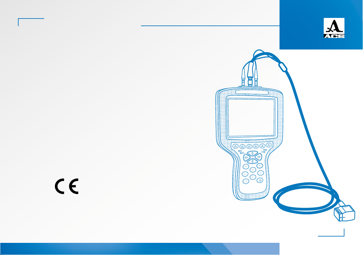
TFM Ultrasonic Flaw Detector A1525 SOLO
Operation Manual
5
ACOUSTIC
CONTROL
SYSTEMS
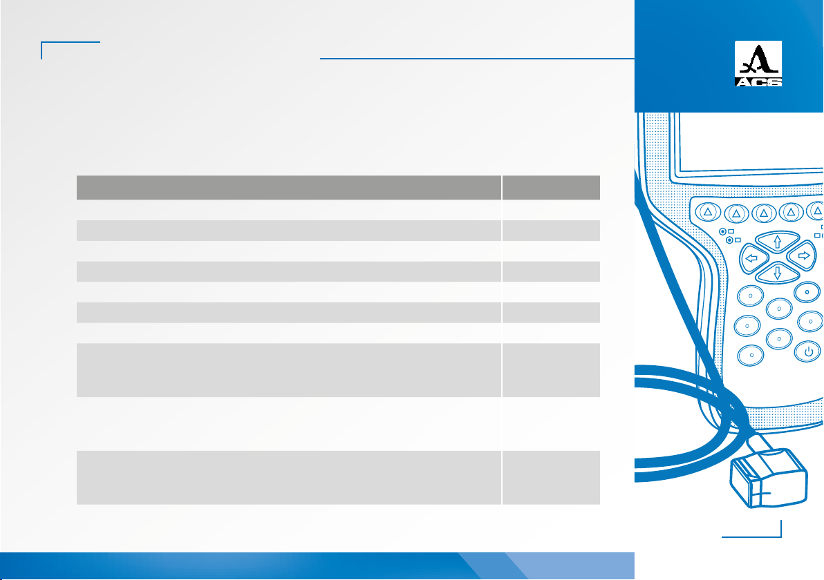
2.3 OPERATING DEVICE MODES .....................................................................................................................................................19
2.3.1 Setup for TOMOGRAPH mode........................................................................................................................................19
2.3.2 Setup for FLAW DETECTOR mode.............................................................................................................................32
2.4 TOMOGRAPH mode..........................................................................................................................................................................54
2.4.1 Device screen in TOMOGRAPH mode .....................................................................................................................56
2.4.2 Gating within a Frame.........................................................................................................................................................56
2.4.3 Tomograph Display Features – Continued..........................................................................................................58
2.4.4 Sensitivity setting using SAC (Spatial Amplitude Correction)..............................................................60
2.4.5 Tomograph Frame evaluation modes.....................................................................................................................66
2.4.6 Magnify (Zoom) control ......................................................................................................................................................67
2.4.7 TOMOGRAPH Freeze mode ............................................................................................................................................68
2.4.8 TOMOGRAPH Scanner mode........................................................................................................................................70
3 MAINTENANCE.............................................................................................................................................................. 77
3.1 Power supply and power consumption..............................................................................................................................77
3.2 Maintenance frequency .................................................................................................................................................................77
3.3 Potential problems .............................................................................................................................................................................77
3.4 Storage .........................................................................................................................................................................................................77
4. TRANSPORTATION.....................................................................................................................................................78
This operation manual contains specifications, device, and operating
principle descriptions for the correct use of the A1525 SOLO ultrasonic
flaw detector.
Before operating this device, please carefully review this manual.
Only properly trained and qualified personnel should operate this device.
Please check local codes and regulations regarding any required certifi-
cations needed before use.
The manufacturer continually upgrades this device, thereby increas-
ing reliability and operational convenience. Consequently, these new fea-
tures may result in significant changes not mentioned in this manual
version. Consult with your local agent or the factory if there are questions
regarding operational characteristics not found within this manual.
ACS-Solutions GmbH
Science Park 2
66123 Saarbrucken, Germany
Phone: +49 (0) 681-96592270
Fax: +49 (0) 681-96592280
Website: www.acs-international.com
Issue date: 04.07.2019
Manufacturer: