New Cosmos Electric KS-7O User manual

Oxygen Detector
KS-7O
Instruction Manual
Keep this manual for easy reference.
Carefully read this manual prior to use.
This manual describes the standard model. If your unit has end-user-specific
options, this manual will be superseded by your delivery specifications.
Instruction Manual No.
GAE-052-06
June 2023

Table of Contents
1. Introduction ................................................................................................................................ 1
2. General Precautions .................................................................................................................. 2
3. Package Contents ..................................................................................................................... 3
4. Unit Dimensions and Components ............................................................................................ 4
4-1. Outer Appearance .................................................................................................................. 4
4-2. Inner Components .................................................................................................................. 5
5. Installation ................................................................................................................................. 6
6. Wiring ........................................................................................................................................ 9
6-1. Pin Terminal/Insulating Sleeve Installation ...........................................................................10
6-2. Wire Connection/Disconnection to/from Terminal Block ...................................................... 11
6-2-1. Power Terminal Block ....................................................................................................... 11
6-2-2. External Output Terminal Block ......................................................................................... 11
6-3. Cable Tie Installation ............................................................................................................ 11
6-4. AC Power Cable (PC0125) Wiring Procedure .....................................................................12
7. Operation .................................................................................................................................13
7-1. Precautions before Use ........................................................................................................13
7-2. Operating Procedure ............................................................................................................13
7-3. LCD Operation .....................................................................................................................15
7-3-1. LCD ...................................................................................................................................15
7-3-2. Normal Operation Status ...................................................................................................15
7-3-3. Full Scale and Alarm Set Values Display ..........................................................................16
7-3-4. Peak Value Display and Reset ..........................................................................................16
7-3-5. Operation during Gas Alarm .............................................................................................16
7-4. User Mode ............................................................................................................................17
7-4-1. User Mode Operation ........................................................................................................17
7-4-2. Switching Maintenance Mode On/Off [Mode1] .................................................................18
7-4-3. Zero Adjustment [Mode 2] .................................................................................................19
7-4-4. Span Adjustment (21.0vol% Adjustment) [Mode 3] ...........................................................19
7-4-5. Alarm Test [Mode 4] ..........................................................................................................20
7-4-6. Alarm History [Mode 5] ......................................................................................................21
7-4-7. Clock Setting [Mode 6] ......................................................................................................22
7-5. Maker Mode .........................................................................................................................23
7-5-1. Maker Mode Activation ......................................................................................................23
7-5-2. Operating Time Refresh ....................................................................................................23
7-5-3. Alarm Set Value Change ...................................................................................................24
8. Maintenance ............................................................................................................................26
8-1. Inspection Contents and Frequency ....................................................................................26
8-2. Sensor/Backup Battery/Clock Battery Replacement............................................................28
9. Troubleshooting .......................................................................................................................31
10. Specifications.........................................................................................................................33
11. Warranty ................................................................................................................................34
12. Expected Sensor Life ............................................................................................................34
13. Detection Principle ................................................................................................................35
14. Glossary ................................................................................................................................36
15. Proper Product Disposal at End of Life .................................................................................37

- 1 -
1. Introduction
Thank you for purchasing the New Cosmos KS-7O oxygen detector.
To ensure safe and reliable operation, please read this instruction manual prior to use.
This unit detects oxygen leakage/deficiency in working environments, e.g., semiconductor
manufacturing plants and laboratories, and relays the oxygen concentration value as an analog
signal (4-20mADC) to external devices while simultaneously displaying the concentration value on
its display.
Oxygen levels are monitored, and if the concentration reaches a preset level, the unit will produce
audio/visual alarms and activate relay contacts.
This manual uses Danger, Warning, Caution and Note symbols to draw attention to
procedures, materials, methods, and processes, which require particular attention.
: Indicates an imminently hazardous situation that can result in
death or serious injury.
: Indicates a potentially hazardous situation that may result in death
or serious injury.
: Indicates a hazardous situation that may result in minor injury or
property damage.
: Provides information on product handling.
DANGER
CAUTION
WARNING
NOTE
- 2 -
2. General Precautions
Carefully read this manual prior to use.
Follow the precautions below to ensure safe operation.
Only use this product in accordance with the applicable laws and regulations.
Only a qualified electrician with knowledge of wiring and installation procedures should perform
wiring and installation.
In the event of a gas alarm, follow the safety procedures in accordance with your
company's regulations.
This product is not explosion-proof and should not be installed in a hazardous area.
Secure the cover by tightening the two fastening screws. Proper gas detection is not
possible if the cover is not tightly closed.
WARNING
Operation during power outage
In the event of a power outage during operation, the detector will cease operation if the
backup battery is not installed. The detector will automatically resume operation once
power is restored, as long as the main power switch, under the cover, is in the on (up)
position. A backup battery is included in the package (not pre-installed) when delivered.
Install it into the detector if the detector needs to continue running during a power outage.
If the backup battery level becomes very low while the detector operates on the backup
- LCD. If the detector
continues operating while "E-B" is displayed, it will cease operation automatically to
prevent over-discharge. In this case, the detector will not automatically resume operation
even if power is restored.
Remove the backup battery from the detector before a planned power outage etc., if the
detector is expected to operate on the backup battery for an extended period of time.
Refer to 8- removal/
ill not be affected
whether the backup battery installed or removed.
NOTE
Do not disassemble, modify, or alter the structure of this unit or its electrical circuits.
Doing so may compromise the performance of the product.
This product is not drip-proof and should be kept away from water.
-layer
monitoring software, perform a 21% suppression setting using the high-layer monitoring
software.
ranges from 250 to 500 (contingent on full scale
setting). Because of the difference in resolution or number of displayed gas
concentration digits between this product and high-layer monitoring software, or
connected impedance, some errors in displayed gas concentration value may be
observed.
If the fault threshold needs to be set via analog output, set it to 1.0 mA.
To comply with JIS T 8201:2010 (Japanese Industrial Standard), your unit should be
configured for manual-resetting. Specify manual-resetting type at time of order. If a
self-resetting type is chosen and manual-resetting is maintained using a high-layer
system, a self-resetting type of detector can be used to comply with this standard.
CAUTION

- 3 -
3. Package Contents
The following items are included in a standard package. If any items are missing or damaged,
please contact New Cosmos or its authorized representative for replacement.
Item Quantity
Description
Oxygen detector 1 KS-7O
Mounting screw 2 M5x12 with spring washer (wall mounting)
Cable tie 1 To be used to bundle electric cables
Pin terminal 9 To be crimped to cables and inserted into the terminal
block
Insulating sleeve 9 To be installed in a crimped pin terminal to provide
insulation
Instruction manual 1 This manual
Inspection certificate 1
Backup battery 1 CR2 lithium battery
AC power cable
(Optional) 1
100 VAC power cable with 2-pin power plug at one end
and two pin terminals at the other end
Length: 2.5 m
Note: AC power cable is not included unless specified at
the time of order, even though your unit has AC power
option.

- 4 -
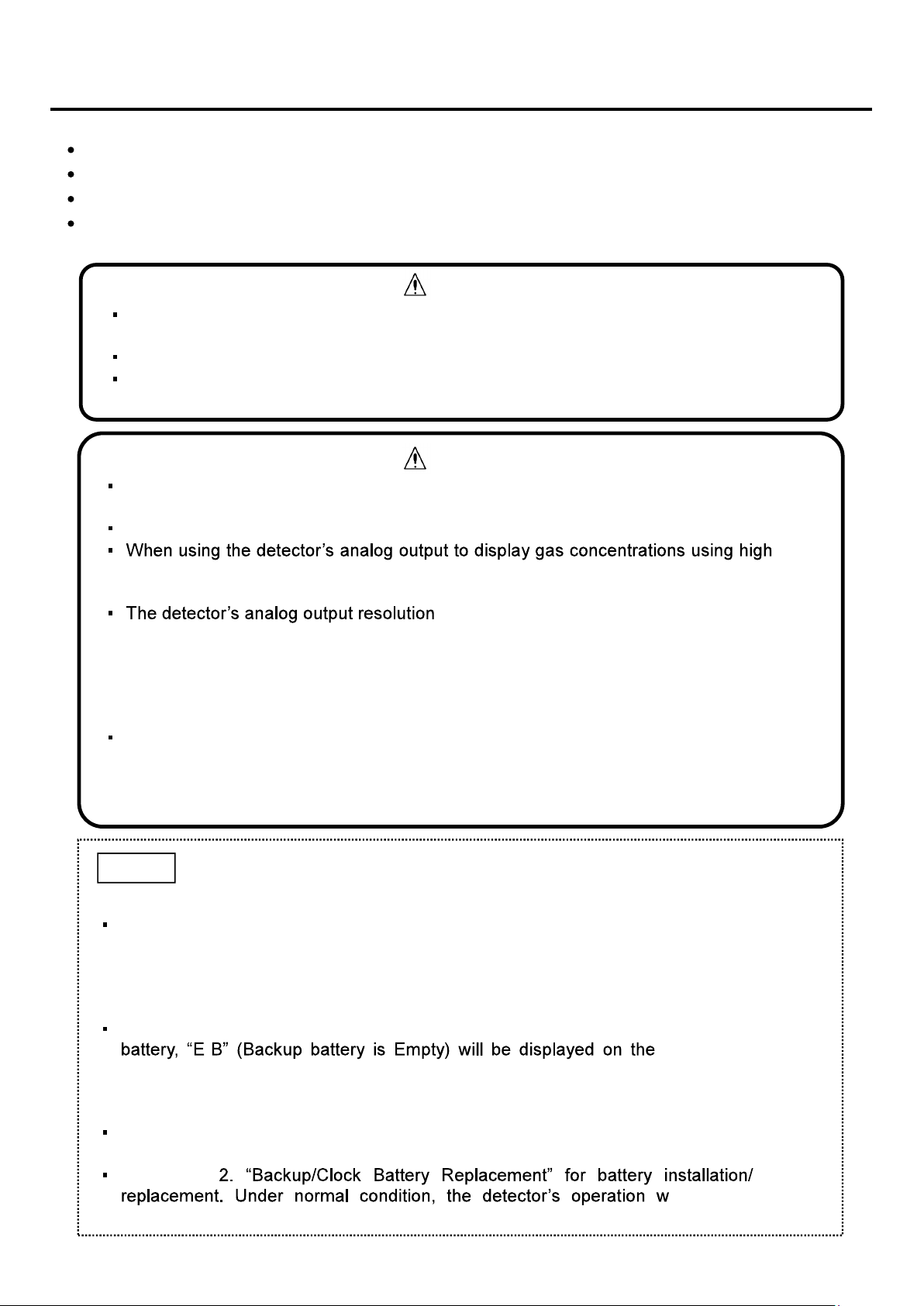
4. Unit Dimensions and Components
4-1. Outer Appearance
Item Component Description/Function
1 Cover
Slide up and lift the cover to access to the main power switch and to
wire external cables. This cover is normally closed.
2 Screw cover Houses one mounting screw, and two fastening screws
that attach the
cover to the unit. This cover is normally closed.
3 Gas detection port Gas inlet to the oxygen sensor.
4 Status indicator
(red/amber/green)
During normal operation all three green internal LEDs are lit.
In the
event of an 1st/2nd stage gas alarm, four internal amber
/red LEDs
light sequentially.
5 LCD Displays oxygen concentration, parameter values, error code,
and
status icons.
6 AL2 alarm LED (red) Flashes red in the event of a 2nd stage gas alarm. The LED
will
become solid if reset by pressing the RESET button.
7 AL1 alarm LED (amber) Flashes amber in the event of a 1st stage gas alarm. The LED
will
become solid if reset by pressing the RESET button.
8 (Up) button
During normal operation, press to display the highest
peak value of
oxygen concentration after powering-up on the LCD.
Used for making settings in combination with other button operation.
9 (Down) button
During normal operation, press to display the lowest
peak value of
oxygen concentration after powering-up on the LCD.
Used for making settings in combination with other button operation.
10 RESET button During normal operation, press to display the full scale and alarm set
values. Used for muting an on-going audio alarm.
11 POWER button Press and hold for 3 seconds to turn on/off the detector.
12 Speaker opening Opening for audio.
13 Cable entry (3 places)
Make a cutout (cable entry) with a nipper to connect external cables to
the terminals.
14 Maintenance button Recessed button used for making settings.
Dimensions are in mm.
- 5 -
4-2. Inner Components
Item Component Description/Function
1 Cover Slide up and lift the cover to access to the main power switch and
to wire external cables. This cover is normally closed.
2 Screw cover Houses one mounting screw, and two fastening screw
s that attach
the cover to the unit. This cover is normally closed.
3 Fastening screw (2 places) Located under the screw cover.
Screws that attach the screw cover to the unit.
4 Terminal block Connect to external wiring.
5 Main power switch Turns on/off the main power.
- 6 -
5. Installation
This product is not explosion-proof and should not be installed in a hazardous area.
WARNING
Leave a distance of more than 30mm from each side of the detector for
removal purpose.
Leave a distance of more than 50mm from the top of the detector to allow the
cover to slide open.
Leave enough space for cable wiring below the detector.
NOTE
Avoid strong mechanical shock, impact or vibration to the detector by dropping or bumping.
Failure to do so may impair the performance of the detector.
Do not install the detector in the following conditions.
- Outdoors
- Exposure to water spray
- Outside the following operating temperature/humidity
-10 to +40 °C (no rapid temperature change)
30 to 85% RH (no condensation)
- Presence of corrosive gas
- Exposure to impact or vibration
- Presence of high frequencies or a magnetic field
- Exposure to electrical noise
Install the detector in a location that ensures easy access for maintenance.
For detecting oxygen deficiency, the detector should be installed at head height in a place
free from obstruction to the gas detection port.
When used in a measurement environment where the atmospheric pressure is different
from the standard atmospheric pressure, e.g., at a high altitude, the measurement value
should be adjusted to compensate for the oxygen sensor s pressure dependence.
Secure the cover by tightening the two fastening screws. Proper gas detection is not
possible if the cover is not tightly closed.
CAUTION

- 7 -
Wall-mount the detector using two M5 mounting screws (pitch: 134) according to the following
procedure.
1. Open the screw cover.
2. Loosely install the mounting screw (top).
3. Loosen the two fastening screws.
4. Slightly pull the cover forward.
2. Loosely install the
mounting screw (top)
3. Loosen the two fastening screws
4. Pull the cover forward
Cover
1. Open the screw cover
Screw cover
Mounting hole
50
Sensor
Space for
cover to slide
Cable entry
Mounting hole
Dimensions are in mm.
50
Mounting hole
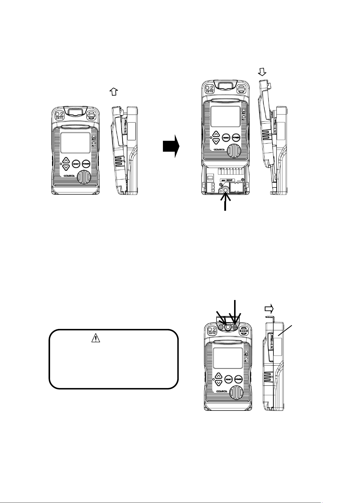
- 8 -
5. Slide the cover up (cover is open).
6. Firmly tighten the mounting screw (bottom) to secure the detector to the wall.
7. Slide the cover down (cover is closed).
8. While pressing down the cover toward the case,
9. tighten the mounting screw (top).
10. Secure the screw cover to the case with the two fastening screws.
11. Close the screw cover.
5. Slide the cover up
6. Tighten the mounting screw (bottom)
7. Slide the cover down
CAUTION
Secure the cover by tightening the
two fastening screws. Proper gas
detection is not possible if the cover
is not tightly closed.
10. Tighten the two fastening screws
Case
9. Tighten the mounting screw
8. Press down the cover

- 9 -
6. Wiring
The knockout holes for cable entry are provided
on the back and bottom of the unit, and can be
removed using a nipper.
Use a shielded cable (with 0.5 to 1.25 mm2 wires)
up to 500 m in length with an outside diameter of
10.5 mm or less.
NO: Normally Open NC: Normally Closed
Remove any power source during wiring work to prevent electric shocks.
After wiring is completed, close the detector s cover to prevent electric shocks.
WARNING
Knockout hole on the bottom
Knockout hole on the back
AC
DC
Power supply
24 VDC or 100 VAC
R P +
S N
E Earth terminal for grounding the detector
Signal + Analog output
4-20mADC
ZA1 1st stage alarm relay contact
(Dry NO or NC)
ZA2 2nd stage alarm relay contact
(Dry NO or NC)
TA Fault alarm relay contact (Dry NO or NC)
COM Common
D Not used
C
New Cosmos is not responsible for the cost or any damage resulting from controlling
external equipment (e.g., interlock) by using the oxygen concentration outputs (e.g.,
analog output, alarm relay contact output) from this product.
Connect wires to their corresponding terminals by referring to the marking on the terminal
block.
Keep the connection cable away from the electrical power line.
When using with external devices, isolate the product s 4-20mA analog output from power
lines of external devices in order to prevent inflow current and noise.
CAUTION
Ex. NO contacts
-
+
R
S
C
D
COM
Signal
E
N S
P R
+
ZA2
ZA1
TA
Refer to page 12 for the wiring procedure
for the optional AC power cable.
Refer to 7-3-2
on page 15 for the operation of the backup
battery.
NOTE
- 10 -
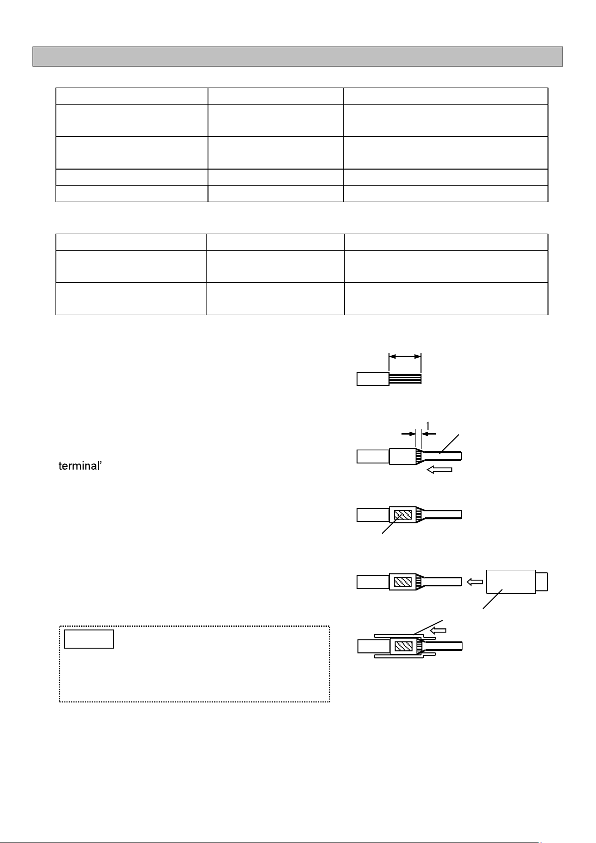
6-1. Pin Terminal/Insulating Sleeve Installation
Recommended parts/tools
Part Model (Manufacturer) Description
Electric cable
Shielded cable (with 0.5-1.25 mm2 wires)
Outer diameter: 10.5 mm or less
Pin terminal TC1.25-16 (Nichifu) (Included in package)
Used for 0.25-1.65 mm2 twisted wire
Insulating sleeve VC1.25 (Nichifu) (Included in package)
Crimping tool NH1 (Nichifu) 1.25
Terminal block (reference)
Part Model (Manufacturer) Description
Power terminal block ML-1400-S1L-3P
(Sato Parts) Dia. 0.65-1.6 mm
External output terminal block
FFKDSA1/H1-5, 08-8
(Phoenix Contact) Dia. 0.2-1.5 mm
1. Wire stripping
Strip the wire.
Recommended stripped wire length: 5.5 mm
2. Pin terminal installation
Insert the stripped wire into a pin terminal until 1 mm
of stripped wire can be seen from the end of the pin
s barrel.
3. Terminal crimping
Crimp the center of the barrel.
4. Insulating sleeve installation
Attach an Insulating sleeve to the crimped pin
terminal.
Completely insert the pin terminal into
the insulating sleeve. Not doing so may
cause an insufficient pin length when
wired to the terminal block, which may
result in a poor connection.
NOTE
Pin Terminal
Barrel
Insulating sleeve
Completely insert
5.5 mm
- 11 -
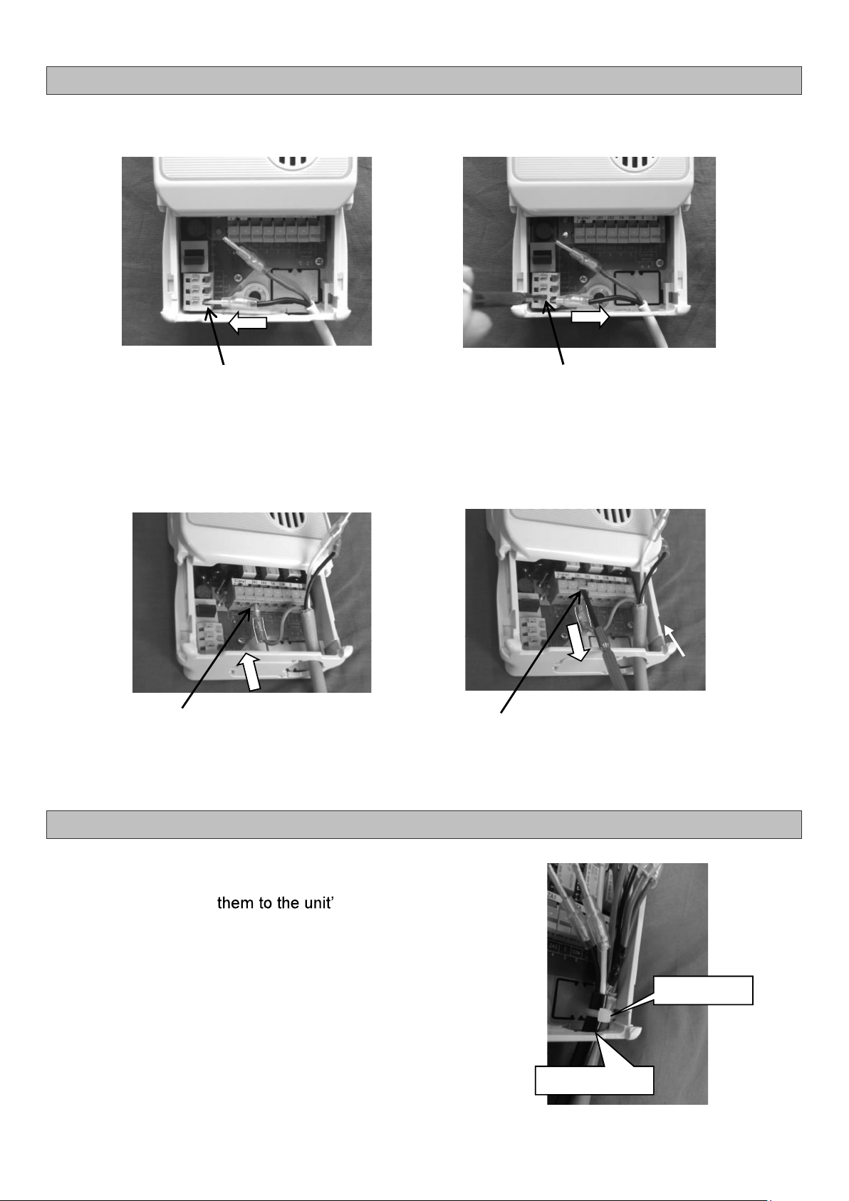
6-2. Wire Connection/Disconnection to/from Terminal Block
6-2-1. Power Terminal Block
6-2-2. External Output Terminal Block
6-3. Cable Tie Installation
Use a cable tie for bundling the in-coming cables through the
cable entry and secure s wall.
The unit has a cable tie holder inside its case near the bottom.
Pre-install a cable tie by feeding it through the tie holder and
make a loop. To easily bundle the wiring of in-coming cables to
the terminal block, feed these cables through this loop and
secure to the case wall.
Cable tie
Cable entry
Insert each pin terminal to its
corresponding slot on the terminal block.
(Connection) (Disconnection)
While pressing the release button with a
precision screwdriver (recommended tip
thickness: 2.6 mm), lift the pin terminal.
(Disconnection)
(Connection)
Insert each pin terminal to its
corresponding slot on the terminal block.
While pressing the release button with a
precision screwdriver (recommended tip
thickness: 3.0 mm), lift the pin terminal.

- 12 -
6-4. AC Power Cable (PC0125) Wiring Procedure
1. Make a cutout (cable entry) on the bottom of
the unit with a nipper.
Note: The knockout holes for cable entry are
provided on the back and bottom of the unit,
and either can be used as cable entry.
Cut here (2 places)
2. Install a cable tie by feeding it through the
tie holder and make a loop.
3. Ensure that the insulating sleeves are
completely installed to the pin terminals of
the AC power cable.
4. Feed the AC power cable through the cable
entry and the loop of the cable tie.
5. Insert the pin terminals into the slots
(Nos. R and S) on the terminal block.
Note: Either pin terminal can be connected to
either slot.
6. Pull the cable tie to secure the AC power
cable to the case wall. Cut off the excess
strap with a nipper.
- 13 -
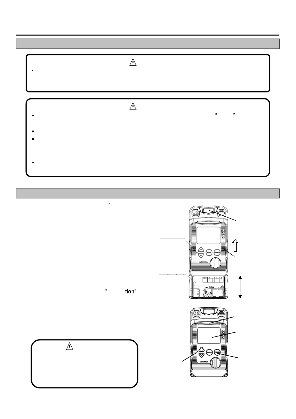
7. Operation
7-1. Precautions before Use
7-2. Operating Procedure
1) Follow Steps 1, 3, 4, and 5 of 5. Installation
to slide up and open the cover (cover is not
fully opened).
1. Open the screw cover.
3. Loosen the two fastening screws.
4. Slightly pull the cover forward.
5. Slide the cover up (cover is open).
2) Set the main power switch to the on (up)
position.
3) Follow Steps 7, 8, and 10 of 5. Installa
to close the cover and tighten the screws.
7. Slide the cover down (cover is closed).
8. While pressing down the cover toward the case,
10. secure the screw cover to the case with the
two fastening screws.
CAUTION
Secure the cover by tightening the
two fastening screws. Proper gas
detection is not possible if the cover
is not tightly closed.
Status indicator
LCD
POWER button
Maintenance
button
Screw cover
Cover
Open
Maintenance
button
Main power
switch
Before tuning on the unit, confirm that the power supply is:
24 VDC±10% when DC power is used.
100 VAC±10% and 50/60Hz±10% when AC power is used.
WARNING
Before turning on the unit, check that all wiring is correct. (Refer to 6. Wiring or delivery
specifications if provided.)
Turn on the unit in clean air.
When the sensor output is not stable, the external relay contact may possibly activate
after the warm-up. To prevent possible activation of the external relay contact after the
warm-up is completed, release the interlocks of the external devices, as needed.
During the warm-up, the analog signal is output and the external relay contacts are
disabled.
CAUTION
- 14 -
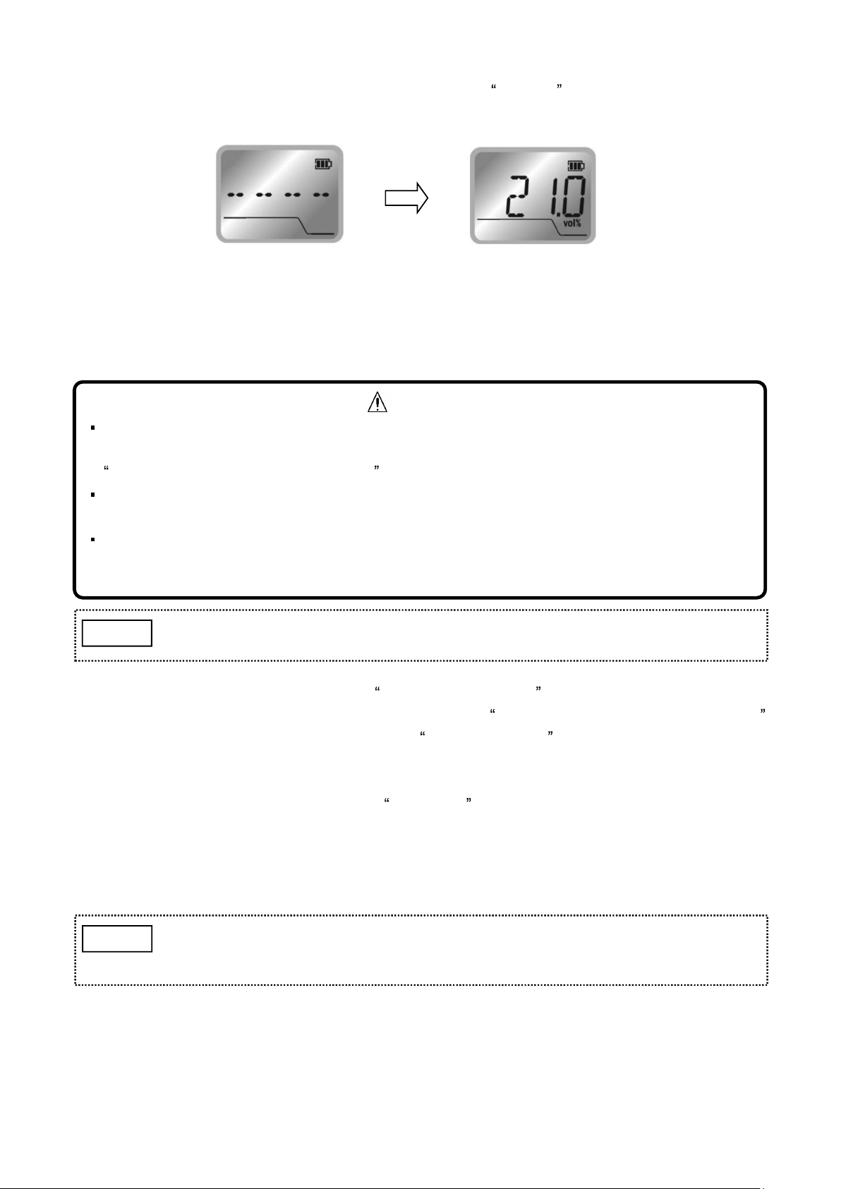
4) Press and hold the POWER button for 3 seconds to turn on the detector (two beeps). The three
green LEDs inside the status indicator start flashing and -- -- -- -- is displayed on the LCD. The
warm-up cycle lasts 30 seconds.
5) When the warm-up cycle is completed, the three green flashing LEDs inside the status indicator
become solid, the gas concentration is displayed on the LCD, and normal operation starts.
6) Perform a span adjustment (21.0 vol%).
1. Enter the User mode. (Refer to 7-4-1. User Mode Operation )
2. Switch the Maintenance mode to ON. (Refer to 7-4-2. Switching Maintenance Mode On/Off )
3. Perform a span adjustment. (Refer to 7-4-4. Span Adjustment )
4. Switch the Maintenance mode to OFF.
7) Perform an alarm test by referring to7-4-5. Alarm Test .
Confirm that an alarm activates.
8) To turn off the detector, press and hold the POWER button for 3 seconds to stop the operation,
then set the main power switch to the off (down) position.
Once the POWER button is turned off, the backup power is not available.
The backup power is activated if the main power switch is turned off, as long as
the POWER button is in the on position.
NOTE
To prevent a possible activation of alarm or external alarm relay contact, switch to the
Maintenance mode to ON before performing a span adjustment. (Refer to 7-4-2.
Switching Maintenance Mode On/Off .)
Check that there is no gas present before span adjustment. Proper gas detection is not
possible if a span adjustment is performed in a gas atmosphere.
When a span adjustment is completed, switch the Maintenance mode to OFF. External
alarm relay contacts or audio alarm are not active while the unit is in the Maintenance
mode.
CAUTION
Use a rounded pin (e.g., precision screwdriver) for pressing the maintenance
button.
NOTE
Warm-up cycle Normal operation
- 15 -
7-3. LCD Operation
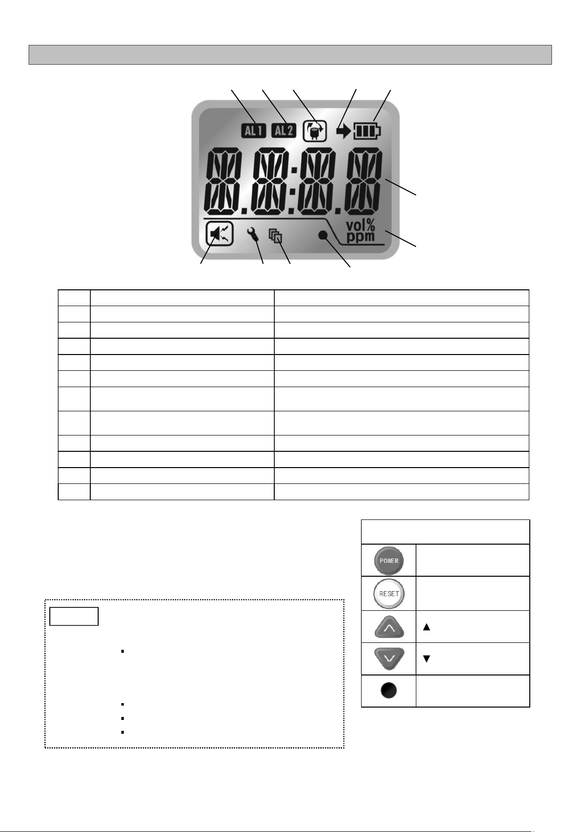
7-3-1. LCD
Item Icon/Display Description/Function
1 Audio alarm icon Always present
2 AL1 icon 1st stage gas alarm notification
3 AL2 icon 2nd stage gas alarm notification
4 Sensor replacement icon Sensor needs to be replaced
5 Backup battery icon Unit is operating on the backup battery
6 Backup battery level indicator Battery level of the backup battery used during power
outage
7 Concentration value and information Oxygen concentration value, parameter values, error
code, etc.
8 Unit of measurement A unit of gas concentration
9 Clock battery level indicator Clock battery level is low
10 Alarm history icon Alarm history is being accessed
11 Maintenance mode icon Maintenance mode is active
7-3-2. Normal Operation Status
During normal operation the green status indicator is fully lit,
the gas concentration value is displayed on the LCD, and
the AL1 and AL2 alarm LEDs are off.
Operation buttons
POWER button
RESET button
(UP )button
(DOWN) button
Maintenance button
1
2
3
4
5
6
7
8
9
10
11
When the detector operates on the backup
battery, unlike when it is driven by 24 VDC
or 100 VAC power supply,
The status indicator is not lit during
normal operation and it sequentially
flashes In the event of a 1st/2nd stage
gas alarm.
The analog output is 0 mA (no output).
The external relay contacts are disabled.
The audio volume is lower.
NOTE
- 16 -
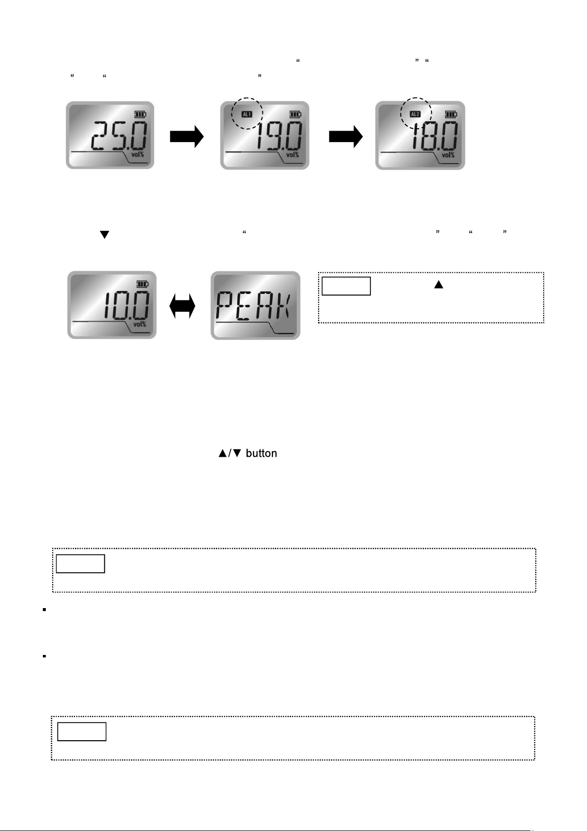
7-3-3. Full Scale and Alarm Set Values Display
Press the RESET button (one beep) to display the full scale concentration , 1st stage gas alarm set
value , and 2nd stage gas alarm set value in sequence.
7-3-4. Peak Value Display and Reset
Press the button (one beep). The lowest peak value after powering-up and PEAK will be
displayed alternately.
(Ex. lowest peak value is 10vol%)
To return to the normal gas concentration display, press the RESET button (one beep).
The display will show the full scale value and alarm set value, then return to the normal gas
concentration display.
To reset the peak value, press the at the same time (two beeps).
The peak value is reset then the display returns to the normal gas concentration display.
7-3-5. Operation during Gas Alarm
When the oxygen concentration reaches the alarm set value, the alarm LED flashes, the status
indicator sequentially-flashes and an audio alarm sounds.
There are two options to clear a gas alarm, manual-resetting and self-resetting. By default, the
detector is set to manual-resetting mode. Please specify the alarm clearance option at the time of
order, if necessary.
The alarm hysteresis range is 0.2vol%. The alarm will not be cleared until the oxygen
concentration exceeds the alarm set value by more than the hysteresis value. E.g., when the alarm
set value is 18.0vol% and an alarm is activated, the alarm will not be cleared until the
concentration reaches 18.3vol% or higher.
Full scale: 25.0 vol% 1st stage gas alarm set value: 19.0 vol%
2nd stage gas alarm set value: 18.0 vol%
Press the button to display
the highest peak value after
powering-up.
NOTE
Alarm relay contact reset: If the RESET button is pressed while the
concentration is outside the alarm set value, the alarm relay contact will return to
its normal position and the alarm LED will turn off.
NOTE
Audio alarm mute: If the RESET button is pressed during a gas alarm, the audio
alarm will be muted and the flashing alarm LED(s) will become solid. If the
RESET button is pressed and held, the alarm will not be muted.
NOTE

- 17 -
7-4. User Mode
7-4-1. User Mode Operation
To enter the User mode, press the maintenance button
while the unit is on. After one beep, 1 and its abbreviated
mode name MT will be alternately displayed.
To select the mode options, use the and buttons.
To confirm your selection, press the maintenance button. To return to the previous step, press the
RESET button.
To execute the selected mode, press and hold the maintenance button for 3 seconds.
To return to the normal operation mode, press and hold the RESET button for 5 seconds.
Mode Mode name Abbreviated mode name
1 Switching maintenance mode on/off MT
2 Zero adjustment 0.0 vol%
3 Span adjustment 21.0 vol%
4 Alarm test AL T
5 Alarm history AL H
6 Clock setting DATE
During the User mode, gas detection, alarm operation, analog output, and
contact output activation are active as during normal operation mode.
However, audio alarm mute and alarm clearance are not active and cannot be
used.
Return to normal operation mode after using the User mode.
NOTE
Use a rounded pin (e.g., precision screwdriver) for pressing the maintenance
button.
NOTE
< 1st stage alarm >
Amber AL1 alarm LED flashes and the status indicator sequentially-flashes amber.
Audio alarm beep: Fast, high and low beep tones.
ZA1 alarm relay contact is closed. (When normally open contacts are used)
< 2nd stage alarm >
Red AL2 and A1 alarm LEDs flash and the status indicator sequentially-flashes red.
Audio alarm beep pattern: Very fast high and low beep tones.
ZA2 alarm relay contact closes and ZA1 alarm remains closed. (When normally open
contacts are used)

- 18 -
7-4-2. Switching Maintenance Mode On/Off [Mode1]
1) Enter the User mode. Press the / button to
select 1 . MT and 1 will be alternately
displayed.
2) Press the maintenance button (one beep).
OFF will flash.
3) Press the button (one beep).
ON will flash.
4) Press and hold the maintenance button for 3
seconds (beep pattern: short long short short) to
confirm the selection.
The maintenance icon is displayed, and 1 and
MT will be alternately displayed, indicating that
the unit is in the Maintenance mode.
5) To exit the Maintenance mode, take Steps 1) to 4)
above to switch the mode from N to "OFF".
Confirm the maintenance icon has turned off.
During the Maintenance mode, the external relay contacts and audio alarm are disabled.
Turn off the Maintenance mode during normal operation.
WARNING
Maintenance icon
If the unit is returned to normal operation mode
while in the Maintenance mode, the
_ _ _ _ will be
alternately displayed and the maintenance icon
will remain displayed.
NOTE
Table of contents
Other New Cosmos Electric Security Sensor manuals


Popular Security Sensor manuals by other brands


Hytronik
Hytronik HIR24 Installation and instruction manual

HME
HME VDB102C installation guide

SMART
SMART TL-2100CP Change Pad Indicator Installation and use instructions

brennenstuhl
brennenstuhl PIR 240 Directions for use

ESYLUX
ESYLUX RC 130i Installation and operating instructions

Master
Master Vega BT quick start guide