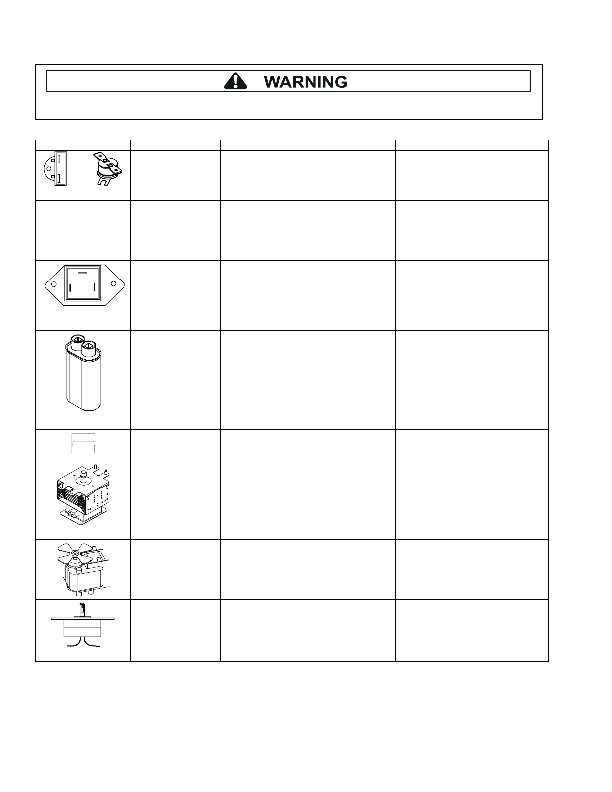
Component Testing Procedures
To avoid risk of electrical shock, personal injury, or death, disconnect power to oven and discharge capacitor
before servicing, unless testing requires it.
July 2012 16500038
©2012 ACP, Inc.
All Amana and Menumaster microwave oven power outputs are rated using the IEC705 standards. Using the IEC705
test method requires precision measurements and equipment that is not practical to be performed in the field. Using
the test shown below will indicate if the oven performance is satisfactory.
Test equipment required:
1000 ml test container and thermometer.
Digital watch / watch with a second hand for use on ovens with electromechanical timers.
Important Notes:
Low line voltage will cause low temperature rise / power output.
Ovens must be on a dedicated circuit, properly grounded, and polarized. Other equipment on the same
circuit may cause a low temperature rise / power output.
This test and results are not a true IEC705 test procedure and are only intended to provide servicers with an
easy means of determining if the microwave oven cooking output is correct.
Procedure
1. Fill the test container to the 1000 ml line with cool tap water.
NOTE: Water temperature should be approximately 60° F / 16° C.
2. Using the thermometer, stir water for five to ten seconds; measure, and record the temperature (T1).
3. Place test container of water in the center of oven cavity and close door.
4. Heat the water for a 33-second full power cycle.
NOTE: Use a digital watch or a watch with a second hand for ovens with electromechanical timers.
5. At end of the cycle, remove test container. Using the thermometer, stir water for five to ten seconds and record
temperature (T2).
6. Subtract the starting water temperature (T1), from the ending water temperature (T2) to obtain the temperature
rise (∆T).
7. If the temperature rise (∆T) meets or exceeds the minimum, the test is complete. If the temperature rise (∆T)
fails to meet the minimum temperature rise, test the line voltage to verify it is correct. Then repeat steps 1 - 6
making sure to change the water. If the temperature rise (∆T) fails to meet the minimum temperature rise again
the oven will require service.
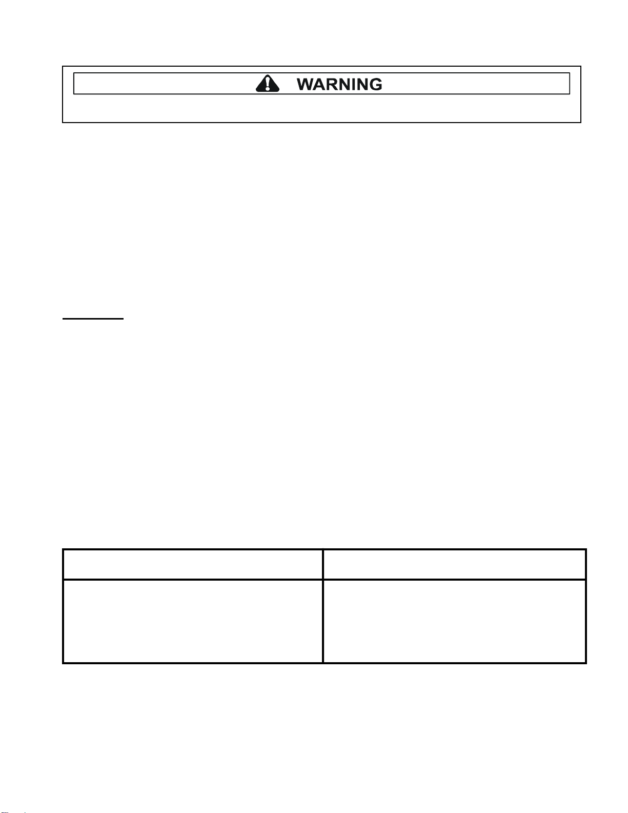
Minimum Temperature Rise at Thirty -Three (33) Seconds Run Time
∆T Cooking ∆T Cooking ∆T Cooking ∆T Cooking
(°F) Power Output (°F) Power Output (°C) Power Output (°C) Power Output
10..................1000 20 .................2000 5 ...............1000 11 ............2000
11..................1100 21 .................2100 5.5.............1100 11.5.........2100
12..................1200 22 .................2200 6.5.............1200 12............2200
14..................1400 24 .................2400 7.5.............1400 13............2400
17..................1700 25 .................2500 9.5.............1700 13.5.........2500
18..................1800 27 .................2700 10..............1800 15............2700
19..................1900 30 .................3000 10.5...........1900 16.5.........3000