Humless CampPower SIM-700 User manual

ATTENTION:
Please follow the instructions in this user manual and pay close
attention to all warnings. Please DO NOT operate before reading this
USER MANUAL.
USER MANUAL
SIM-700 PORTABLE INVERTER

NOTICES
•Humless Rolling Power™reserves the right to modify or change parts of,
or all the specications and pricing policies at company’s sole discretion.
•Humless Rolling Power shall not be liable for losses caused by either
incidental or consequential use in connection with the furnishing, use or
performance of this manual as well as any information contained herein.
•This document may not be copied or edited without Humless Rolling
Power’s prior written approval.
CONTACT US
If you have any problems or need help when using our products,
please contact Humless Rolling Power, your local distributor, or visit
www.HumlessRollingPower.com • +1.866.476.2586
©2018 Humless Rolling Power, LLC. All Rights Reserved.
Publication Number: SIM700-001
The information provided in this documentation contains general descriptions and/
or technical characteristics of the performance of the products contained herein. This
documentation is not intended as a substitute for and is not to be used for determining
suitability or reliability of the products for specic user applications. It is the duty of any such
user or integrator to perform the appropriate and complete risk analysis, evaluation and
testing of the products with respect to the relevant specic application or use thereof. Neither
Humless Rolling Power nor any of its afliates or subsidiaries shall be responsible or liable for
misuse of the information contained herein.
i

11
ii
TABLE OF CONTENTS
1. INTRODUCTION ........................................1
1.1 Foreword ............................................1
1.2 Product Description. . . . . . . . . . . . . . . . . . . . . . . . . . . . . . . . . . . . 1
1.3 Product Diagram ......................................1
1.4 Safety Precautions ....................................2
2. OPERATING INSTRUCTIONS ..............................2
2.1 Product Installation & Connection Steps ...................2
2.2 Precautions ..........................................3
2.3 AC Priority Mode ......................................4
2.4 AC/Shore Power/Generator Power Cut Off..................4
2.5 No AC or Solar Input ...................................4
2.6 PV Solar Priority Mode .................................4
3. PRODUCT PANEL & DISPLAY DETAILS .....................5
4. ON/OFF INSTRUCTIONS .................................5
4.1 AC Priority ...........................................5
4.2 PV Priority Switch .....................................5
4.3 Turning On Steps......................................6
4.4 Turning Off steps ......................................6
5. LCD DISPLAY...........................................7
6. SPECIFICATIONS........................................8

11
1. INTRODUCTION
1.1 Foreword
This manual provides a detailed introduction regarding the use of the
Camp Power SIM-700. Please read the user instructions thoroughly
in order to get the maximum benet from your SIM-700. Should any
questions arise during installation, please contact your installer or customer
support (see page i).
1.2 Product Description
This manual provides detailed instructions for the Camp Power SIM-
700. The SIM-700 is a smart, portable, home and camping, inverter. This
inverter has pure sine wave output, with exceptional compatibility, which
can be connected to refrigerators, electric fans, televisions, uorescent
lamps etc, without damage to devices or batteries. The SIM-700 is safe,
reliable, and easy to use.
1.3 Product Diagram
ii
LCD Display 4 ON/OFF 7 Battery 12VDC Cable 10 Circuit Breaker
Indicators 5 PV Solar Input 8 PV/AC Priority Switch 11 AC Outputs
1
2
AC Power Switch 6 PV Solar Switch 9 Cooling Fan 12 AC Power In Cable3
15
6
7
9
11
12
10
8
2
34

3
2
1.4 Safety Precautions
1. Please read the “Safety Precautions” before use to ensure safe
and proper operation of this unit. Keep this manual in a safe and
secure place. Warranty will be null and void if the user fails to follow all
warnings and cautions in this manual.
2. Please follow all warnings when operating this unit.
3. Keep this unit away from direct sun, rain, and humid conditions.
4. Keep this unit away from heat sources like, re, electric heaters,
ovens, furnaces, etc.
5. ATTENTION: Keep approximately 6 inches along top, sides,
front and back of unit for ventilation. Ventilation is crucial for proper
operation. Under heavy loads and in higher temperatures more
ventilation may be required for the unit to function.
6. When cleaning, always turn the power off. Use a clean dry cloth and
do not use liquids to clean this product.
7. In the event of electrical re, use only dry powder re extinguisher.
There is a danger of electric shock if a liquid re extinguisher is used.
8. DO NOT open the case or touch any internal parts or wiring. Only
connect cables to the provided external ports. Warranty is voided if
case is opened.
9. Please contact Humless Rolling Power for any repairs or
maintenance needs. (See page i for contact information)
2. OPERATING INSTRUCTIONS
2.1 Product Installation & Connection Steps
Step 1: Please open the packaging carton to verify that the product is
undamaged due to shipping.
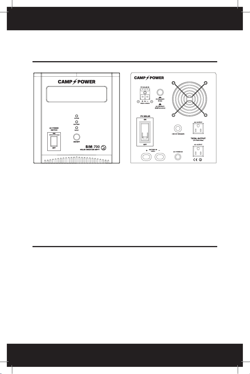
ATTENTION: To avoid serious DAMAGE to the unit, always connect the
battery properly. Positive to Positive (+) and Negative to Negative (-).

3
2
Always connect the solar panels properly, check the voltage, polarity of
positive and negative carefully before use.
Step 2: Choose the units working mode: For solar energy systems,
select the PV priority, otherwise AC priority or grid/shore power/
generator should be used.
Step 3: To start unit, press and hold the ON/OFF button for 3 seconds.
2.2 Precautions
1. ATTENTION: Connect properly to the battery and solar panel,
reversed polarity or high voltage will cause serious damage to unit.
2. ATTENTION: Don’t install this product outdoors. Placing in
or near water may cause electric shock. Always place in a
dry location.
3. ATTENTION: Device may become warm to the touch when
in use. Ensure there is adequate ventilation around unit, and keep away
from ammable materials. Keep unit dry at all times.
4. If the unit malfunctions, disconnect the main AC power switch and
then shut unit down. Disconnect the battery and solar panel and any
AC/shore power/generator. In the event of failure please contact your
Humless Rolling Power dealer.
5. The unit has a high temperature shutdown feature, if this happens it
will give a beeping sound. Disconnect output loads, turn off solar (PV),
and let the unit cool down. After unit has cooled down you can restart
the unit.
6. If the power load is to high the unit will make a beeping sound
before shutting down, in that event restart the unit.

5
4
2.3 AC Priority Mode
When AC power supply is normal: AC input will provide power to AC
outputs through inverter. At this time, PV (Solar) gives power to batteries
only through MPPT control system.
2.4 AC/Shore Power/Generator Power Cut Off
The system automatically acts as a UPS (Universal Power Supply), this
will allow constant AC output. If the PV solar input does not provide
enough power, then the batteries will continue to supply power until they
are drained.
2.5 No AC or Solar Input
The system will use battery storage to supply loads and AC power supply.
2.6 PV Solar Priority Mode
1. During the day, with ample sunlight, and with the AC switch on, the
solar MPPT controller will supply current from solar to power loads
through the inverter (AC input as a standby), and charge the battery at
the same time.
2. During the evening (or rainy days, with no sun), and AC power
switch is on, the system will provide power through battery rst,
discharge until low voltage protection, and then automatically switch
to the AC Input and provide the power to load through the inverter.
Note: Prior to a low voltage shutdown a warning beeping sound will occur.

5
4
3. PRODUCT PANEL & DISPLAY DETAILS
TOP Green LED: Solar panel connect state. Long light means normal.
Light off or ash means connection is unusual.
Middle Yellow LED: Battery connect state. Long light means normal, light
off or ash means connection is unusual.
Bottom Red LED: Means abnormal state, light means solar part abnormal.
4. ON/OFF INSTRUCTIONS
4.1 AC Priority
1. Turn On: Hold on/off for 3 second to power unit on. When the AC
Power Switch is on, inverter will work in AC mode. During this mode the
battery will charge.
2. Turn Off: Hold on/off for 3 seconds to put unit in standby/off mode.
4.2 PV Priority Switch
1. On: PV Solar supplies power to the battery. AC output uses inverter to
power loads. PV Solar is main input supply.

66
7
2. AC charging is main charging for unit. If AC switch is on and battery
voltage is low unit will charge when AC Power is available.
4.3 Turning On Steps
ATTENTION: Do not use unit unless connected to the proper battery!
Step 1: Please ensure the battery is connected properly (positive/
negative and voltage is consistent with the product the). Only use 12V
batteries for the SIM-700.
Step 2: Please ensure the PV solar panel is properly connected
(positive/negative and voltage parameters consistent with the product
identication), and then turn on the solar input switch.
Step 3: Press the button “On/Off” for 3 seconds, and start the unit.
Step 4: Turn on the PV Solar panel input switch, and it will charge
automatically.
4.4 Turning off steps
1. Turn off the loads or unplug connected devices.
2. Press the shut-down (“Off”) manually for 3 seconds, and cut
the output.
3. Unplug the power AC input cord.
4. Turn off the PV Solar switch on the back panel (If no need Solar
panel charging).

66
7
5. LCD DISPLAY
AC/Grid power input normal, device though AVR
supplies output.
AC/Grid power input normal, battery through inverter
supplies AC output.
Temperature is to high, device cuts off output.
Battery over voltage, short circuit, high temperature.
AC/Grid power input is over voltage.
AC/Grid power input is low voltage.
Loading exceeds device’s rated power.
Loading bar showing the loading situation.
Input voltage indication.
Output voltage indication and frequency indication.
Battery bar showing the battery capacity, when in charging,
the bar will be ashing.

6. SPECIFICATIONS
88
9
ledoM
Power Capacity: AC out
Battery voltage
Working mode PV(Photovoltaic priority) / AC (AC priority) Optional
Input voltage
range 15Vdc-50Vdc
Max. charge
current 40A
PV
Max. conversion
efficiency 98%
Display Panel indicator
light LED Graphic Screen LED lights
Input voltage
range 100Vdc~120Vdc
Input frequency
range
45-65 Hz (Automatically transfer to inverter
power when over frequency
Output voltage
range 100Vac~120Vac
Input PF.
(AC/DC) 98%
Efficiency Mains mode ≥ 96%
Linear load ≤ 3%
≤ 50dB
10% ~ 90% (Non Condensed)
32°F ~ 104°F
3-Prong-15Amp
1 time / 1S, silence auto after 5S /
Low voltage alarm will beep
1 time / 1S and flash battery last grid
1 time / 1S and display “overload” grid /
High load alarm will beep before shutdown
Inverter mode ≥ 80%
tnerrucegrahC
daolrevosniaM
Mains
status
(Optional)
tiucrictrohS
Inverter output
voltage
ycneuqerftuptuO
Wave form
distortion
4Ms typical value Max.6 Ms
Efficiency
Inverter overload 110%-130% shutdown at 30s,
130%-150% shutdown at 3s
Inverter
output
tiucrictrohS Systems automatically shut down
lamronbasniaM
yrettabwoL
Alarm
daolrevO
stekcostuptuO
Others Ambient
temperature
Ambient humidity
Noise
SIM-700
700W
12Vdc
20A
Warning until decrease load
Yes
120Vac
50 Hz / 60 Hz ± 0.3Hz frequency adaptive
PV-AC transfer
time

88
9
ledoM
Power Capacity: AC out
Battery voltage
Working mode PV(Photovoltaic priority) / AC (AC priority) Optional
Input voltage
range 15Vdc-50Vdc
Max. charge
current 40APV
Max. conversion
efficiency 98%
Display Panel indicator
light LED Graphic Screen LED lights
Input voltage
range 100Vdc~120Vdc
Input frequency
range
45-65 Hz (Automatically transfer to inverter
power when over frequency
Output voltage
range 100Vac~120Vac
Input PF.
(AC/DC) 98%
Efficiency Mains mode ≥ 96%
Linear load ≤ 3%
≤ 50dB
10% ~ 90% (Non Condensed)
32°F ~ 104°F
3-Prong-15Amp
1 time / 1S, silence auto after 5S /
Low voltage alarm will beep
1 time / 1S and flash battery last grid
1 time / 1S and display “overload” grid /
High load alarm will beep before shutdown
Inverter mode ≥ 80%
tnerrucegrahC
daolrevosniaM
Mains
status
(Optional)
tiucrictrohS
Inverter output
voltage
ycneuqerftuptuO
Wave form
distortion
4Ms typical value Max.6 Ms
Efficiency
Inverter overload 110%-130% shutdown at 30s,
130%-150% shutdown at 3s
Inverter
output
tiucrictrohS Systems automatically shut down
lamronbasniaM
yrettabwoL
Alarm
daolrevO
stekcostuptuO
Others Ambient
temperature
Ambient humidity
Noise
SIM-700
700W
12Vdc
20A
Warning until decrease load
Yes
120Vac
50 Hz / 60 Hz ± 0.3Hz frequency adaptive
PV-AC transfer
time

1010
11
NOTES:

1010
11

1212

©2018 Humless Rolling Power, LLC. All Rights Reserved.
1374 West 200 South, Lindon UT, 84042
www.HumlessRollingPower.com
•083118
1212
Table of contents
Other Humless Inverter manuals