Acromag SP33 0700 Series User manual

USB Programmable, DIN Rail Mount, DC-Powered
Signal Splitters w/ DC Current/Voltage Input and
Dual Isolated Current or Voltage Outputs
Model SP336-0700, DC Current & Low DC Voltage Input
Model SP337-0700, DC ±1V/±10V Medium Voltage Input
Model SP338-0700, DC ±15V/±150V High Voltage Input
USER’S MANUAL
ACROMAG INCORPORATED Tel: (248) 295-0880
30765 South Wixom Road Fax: (248) 624-9234
Copyright 2018, Acromag, Inc., Printed in the USA.
Data and specifications are subject to change without notice. 8501107B

Model SP33X-0700
4-Wire DC I/V Signal Splitter w/USB
Acromag, Inc. Tel: 248-295-0880
- 2 -
https://www.acromag.com
Table of Contents
GETTING STARTED
DESCRIPTION.......................................................................................................4
Key Features........................................................................................................................4
Application ..........................................................................................................................4
Mechanical Dimensions .......................................................................................................5
DIN Rail Mounting & Removal..............................................................................................5
ELECTRICAL CONNECTIONS ............................................................................ 6
SENSOR INPUT CONNECTIONS .......................................................................7
Output Connections.............................................................................................................9
Power Connections ............................................................................................................10
Optional Bus Power Connections .......................................................................................11
Earth Ground Connections .................................................................................................12
USB Connections................................................................................................................13
CONFIGURATION SOFTWARE...................................................................... 14
Quick Overview –Android .................................................................................................14
Quick Overview –Windows ...............................................................................................15
OPERATION STEP-BY-STEP.......................................................................... 18
Connections.......................................................................................................................18
Configuration.....................................................................................................................19
Calibration (Optional) ........................................................................................................22
BLOCK DIAGRAM ............................................................................................. 24
How It Works.....................................................................................................................24
TROUBLESHOOTING....................................................................................... 25
Diagnostics Table ...............................................................................................................25
Service & Repair Assistance................................................................................................26
ACCESSORIES .................................................................................................... 27
Software Interface Package................................................................................................27
USB Isolator.......................................................................................................................27
USB A-B Cable....................................................................................................................27
USB A-mini B Cable ............................................................................................................27
USB OTG Cable...................................................................................................................28
DIN Rail Bus Connector Kit .................................................................................................28
End Stops...........................................................................................................................28
SPECIFICATIONS .............................................................................................. 29
Model Number ..................................................................................................................29

Model SP33X-0700
4-Wire DC I/V Signal Splitter w/USB
Acromag, Inc. Tel: 248-295-0880
- 3 -
https://www.acromag.com
Input .................................................................................................................................29
Output...............................................................................................................................33
USB Interface.....................................................................................................................34
Power................................................................................................................................35
Enclosure & Physical ..........................................................................................................35
Environmental ...................................................................................................................35
Agency Approvals ..............................................................................................................36
Reliability Prediction..........................................................................................................36
Configuration Controls.......................................................................................................37
REVISION HISTORY ......................................................................................... 37
All trademarks are the property of their respective owners.
IMPORTANT SAFETY CONSIDERATIONS
You must consider the possible negative effects of power, wiring, component, sensor, or software failure in the design of
any type of control or monitoring system. This is very important where property loss or human life is involved. It is
important that you perform satisfactory overall system design and it is agreed between you and Acromag, that this is your
responsibility.
The information of this manual may change without notice. Acromag makes no warranty of any kind regarding this
material, including, but not limited to, the implied warranties of merchantability and fitness for its intended purpose.
Further, Acromag assumes no responsibility for any errors that may appear in this manual and makes no commitment
to update, or keep current, the information contained in this manual. No part of this manual may be copied or
reproduced in any form without the prior written consent of Acromag, Inc.
This manual is for 4-wire (separate isolated power) SP300 transmitters that convert DC voltage and current
signals to dual isolated voltage or current output signals. To split microBlox (uB) module inputs similarly,
please refer to our uBSP-P-1 model. If your application requires dual 2-wire (loop-powered) outputs instead,
please refer to similar SP200 series models. For thermocouple input signals, please refer to our SP333 (4-wire)
and SP233 (2-wire loop-powered) models.

Model SP33X-0700
4-Wire DC I/V Signal Splitter w/USB
Acromag, Inc. Tel: 248-295-0880
- 4 -
https://www.acromag.com
GETTING STARTED
DESCRIPTION
Symbols on equipment:
!
Means “Refer to User’s Manual
(this manual) for additional
information”.
The SP33X-0700 models are modeled after ANSI/ISA Type IV transmitters, but with
dual isolated outputs, and are commonly referred to as signal splitters or repeaters.
These units are designed to interface with DC current or voltage sensors depending
on the model, isolate the input signal, and modulate two isolated DC outputs that
may output current or voltage. Units are set up, calibrated, and rescaled using
configuration software and a USB connection to Windows-based PC’s (Windows 7
and later versions only), or using a USB-OTG cable to Android smartphones or
tablets using the Agility mobile app. Units provide adjustable input and output
ranges, dual output signals for voltage or current, three-way isolation, and variable
input filtering.
Key Features
•Digitally configured and calibrated w/ Windows software via USB, or a wired
USB-OTG connection to Android smartphones or tablets.
•Thin 17.5mm wide enclosure for high-density DIN-rail mounting.
•Two models each have separate inputs for DC voltage in two ranges. The
SP336 model has separate inputs for DC voltage and DC current.
•High measurement accuracy and linearity with 16-bit conversion.
•Adjustable/scalable input/output ranges.
•SP336 has DC Current Input for 0-20mA/4-20mA/0-11.17mA/±1mA and DC
Voltage Input for ±0.5V/0-500mV. SP337 has separate DC Voltage inputs for
up to ±1V, and ±10V. SP338 has separate DC Voltage input for high-level
ranges to ±15V, and ±150V. I/O ranges are scalable.
•Dual tandem voltage and current output terminals support your choice of
±10V, ±5V, 0-10V, 0-5V, or 0-20mA, 4-20mA outputs at each output channel.
•Normal or Reverse Acting output.
•Variable digital input filter adjustment.
•Wide-range DC power input from 6-32V.
•Bussed power and/or redundant power ready.
•Wide ambient temperature operation from -40°C to +75°C.
•Thoroughly tested and hardened for harsh environments.
•CE Approved & includes UL/cUL Class 1, Division 2 approvals.
•FCC Conformity Class B.
•ATEX / IECEx Certified for Explosive Atmospheres.
II 3 G Ex nA IIC T4 Gc - 40oC ≤ Ta ≤ +75oC
DEMKO 18 ATEX 2086XIECEx UL 18.0092X
Application
For additional information on
these devices and related topics,
please visit our web site at
www.acromag.com.
These splitters are designed for high-density mounting on T-type DIN rails. Units
may be mounted side-by-side on 0.7-inch (17.5mm) centers and support 6-32V DC
power via terminals on the unit, or optionally via power wired to a DIN-rail bus
connector. Models isolate current or voltage input signals and can mate with
grounded or non-grounded sensors. They drive separately isolated outputs that
drive current or voltage at each output channel with support for 0-20mA, 4-20mA,
or ±10V, ±5V, 0-10V, and 0-5V output ranges.

Model SP33X-0700
4-Wire DC I/V Signal Splitter w/USB
Acromag, Inc. Tel: 248-295-0880
- 5 -
https://www.acromag.com
Mechanical Dimensions
Units may be mounted to 35mm
“T” type DIN rail (35mm, type
EN50022), and side-by-side on 0.7-
inch centers.
WARNING: IEC Safety Standards
may require that this device be
mounted within an approved
metal enclosure or sub-system,
particularly for applications with
exposure to voltages greater than
or equal to 75VDC or 50VAC.
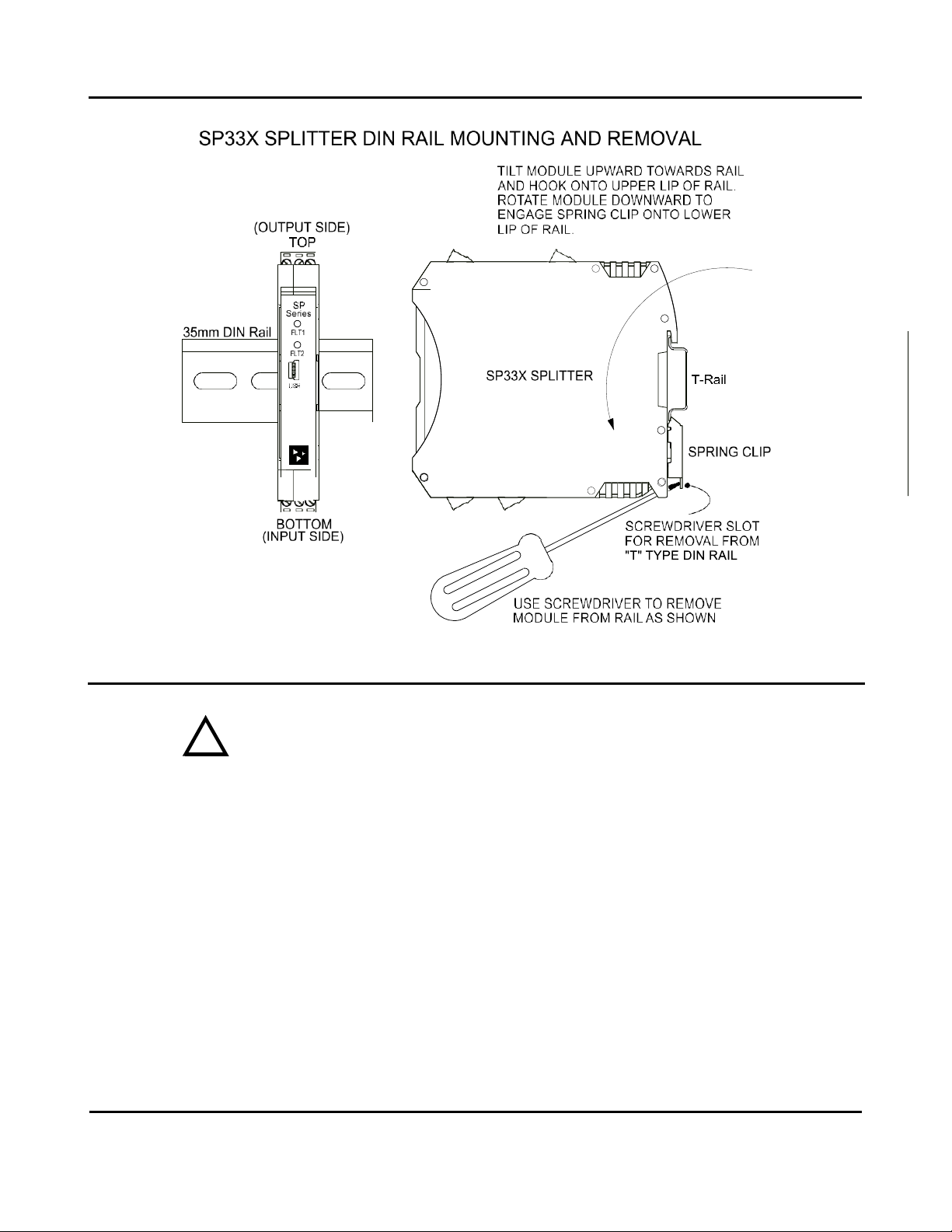
DIN Rail Mounting & Removal
Refer to the following figure for attaching and removing a unit from the DIN rail. A
spring-loaded DIN clip is located on the input side bottom. The opposite rounded
edge at the bottom of the output side allows you to tilt the unit upward to lift it
from the rail while prying the spring clip back with a screwdriver. To attach the
module to T-type DIN rail, angle the top of the unit towards the rail and place the
top groove of the module over the upper lip of the DIN rail. Firmly push the unit
downward towards the rail until it snaps into place. To remove it from the DIN rail,
first separate the input terminal blocks from the bottom side of the module to
create a clearance to the DIN mounting area. You can use a screwdriver to pry the
pluggable terminals out of their sockets. Next, while holding the module in place
from above, insert a screwdriver into the lower path of the bottom of the module to
the DIN rail clip and use it as a lever to force the DIN rail spring clip down while
pulling the bottom of the module outward until it disengages from the rail. Then
simply lift it from the rail.
Model SP33X-0700
4-Wire DC I/V Signal Splitter w/USB
Acromag, Inc. Tel: 248-295-0880
- 6 -
https://www.acromag.com
ELECTRICAL CONNECTIONS
WARNING –EXPLOSION HAZARD –Do not disconnect equipment unless power has
been removed or the area is known to be non-hazardous.
WARNING –EXPLOSION HAZARD –Substitution of any components may impair
suitability for Class I, Division 2.
WARNING –EXPLOSION HAZARD –The area must be known to be non-hazardous
before servicing/replacing the unit and before installing.
Wire terminals can accommodate 14–26 AWG (2.08–0.13mm2) solid or stranded
wire with a minimum temperature rating of 85oC. Input wiring may be shielded or
unshielded type. Ideally, output wires should be twisted pair, or shielded twisted
pair. Terminals are pluggable and can be removed from their sockets by prying
outward from the top with a flat-head screwdriver blade. This model allows current
input to be wired to TB1, and voltage input wired to TB2, but only one input may
drive the output. Strip back wire insulation 0.25-inch on each lead and insert the
wire ends into the cage clamp connector of the terminal block. Use a screwdriver to
tighten the screw by turning it in a clockwise direction to secure the wire (0.5-
0.6Nm torque). Since common mode voltages can exist on signal wiring, adequate
wire insulation should be used and proper wiring practices followed. As a rule,
output wires are normally separated from input wiring for safety, as well as for low
noise pickup. Important –End Stops: For hazardous location installations (Class I,
Division 2 or ATEX / IECEx Zone 2), it should utilize two end stops (like Acromag
1027‐222) to help secure modules to the DIN rail (not shown).
!
Model SP33X-0700
4-Wire DC I/V Signal Splitter w/USB
Acromag, Inc. Tel: 248-295-0880
- 7 -
https://www.acromag.com
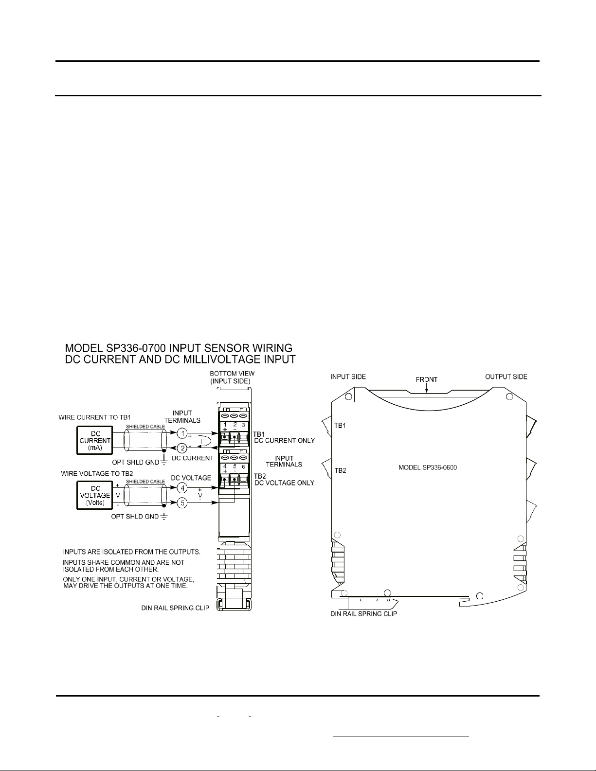
Sensor Input Connections
Sensor wires are wired directly to transmitter input terminals TB1 & TB2 at the
bottom of the module (the spring-loaded DIN clip side), as shown in the connection
drawing below. Observe proper polarity when making input connections.
•Transmitter input signal is isolated from each output channel and one input,
current or voltage, drives both outputs at one time. An output may drive
current or voltage (on separate terminals that share RTN). The input may be
scaled differently for each output.
•Input is polarized ±, observe proper polarity. The positive input is on the left
and labeled “+”, and the negative input is to its right. See connection figure
below per input model.
•SP336 ±20mA DC Current is wired to the upper terminal block TB1 and
±0.5VDC is wired to the lower terminal block TB2.
•SP337 ±1V DC maximum is wired to the upper terminal TB1 and ±10V DC
maximum is wired to the lower terminal block TB2.
•SP338 ±15V DC maximum is wired to the upper terminal TB1 and ±150V DC
maximum is wired to the lower terminal block TB2.


Model SP33X-0700
4-Wire DC I/V Signal Splitter w/USB
Acromag, Inc. Tel: 248-295-0880
- 9 -
https://www.acromag.com
Output Connections
(To DC Current or
Voltage Terminals)
This transmitter is modeled after ANSI/ISA Type 4 transmitters, except with two
outputs, and with unit power separate from the input and each output circuit.
•Output connections are polarized. Tandem current and voltage output
terminals at each isolated output channel share an output return (RTN).
Current output is sourced from I Out+ and returned to RTN. Voltage
output is sourced positive at V Out+ with respect to RTN. Only one channel
output terminal (voltage or current) may be loaded at a time.
•Variations in load resistance have negligible effect on output accuracy
when load limits are respected with respect to output type (see below).
Observe proper polarity. Note that twisted-pair wiring is often used to connect the
longest distance between each field transmitter output and the remote load as
shown above. Additionally, shielded twisted pair wiring is recommended for best
results. An output connection to earth ground at each output return will help
protect the circuit from damage in noisy environments.
WARNING: For compliance to applicable safety and performance standards,
the use of twisted pair output wiring is recommended. Failure to adhere to
sound wiring and grounding practices as instructed may compromise safety,
performance, and possibly damage the unit.
TIP - Ripple & Noise: Place additional capacitance at the load to help reduce the
60Hz/120Hz ripple sometimes present in industrial applications. For large 60Hz
ripple, connect an external 1uF or larger capacitor directly across the load to reduce
excess ripple. For sensitive applications with high-speed acquisition at the load,
high frequency noise may be reduced significantly by placing a 0.1uF capacitor
directly across the load, and as close to the load as possible.

Model SP33X-0700
4-Wire DC I/V Signal Splitter w/USB
Acromag, Inc. Tel: 248-295-0880
- 10 -
https://www.acromag.com
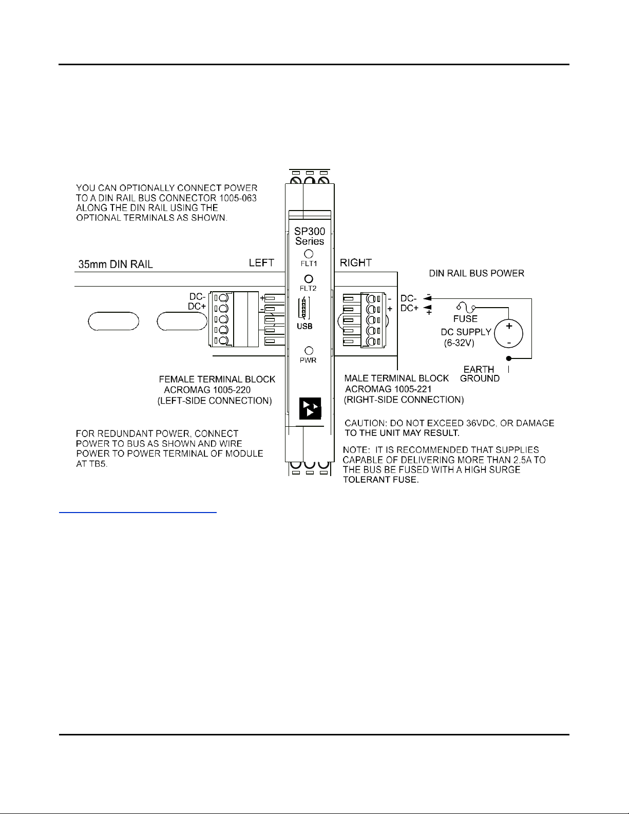
Power Connections
The unit is powered from 6-32V DC (36V DC peak) by connecting power as shown
below. This transmitter can be optionally powered (or redundantly powered) via
the DIN rail bus when coupled to an optional DIN rail bus connector (Acromag
Model 1005-063) with a bus terminal block (Acromag 1005-220 or 1005-221). This
optional power connection method can allow several modules to share a single
power supply without wiring power to each power terminal block individually.
•Power connections are isolated from the input and each output. The
supply voltage should be from 6-32V DC. This voltage must never exceed
36V DC peak, or damage to the unit may result.
•Variations in power supply voltage between the minimum required and
32V maximum, has negligible effect on transmitter accuracy.
•Note the placement of earth ground at power. The power cable shield and
DC- should ideally be grounded closest to the module. The input and
output circuit commons are capacitively coupled to earth ground at DC-
through high-voltage isolation capacitors, offering some protection if their
circuits happen to float relative to power (not recommended).

Acromag, Inc. Tel: 248-295-0880
- 11 -
https://www.acromag.com
Model SP33X-0700
4-Wire DC I/V Signal Splitter w/USB
Power Connections…
CAUTION: Risk of Electric Shock –More than one disconnect switch may be
required to de-energize this equipment before servicing.
IMPORTANT –External Fuse: If unit is powered from a supply capable of delivering
more than 2.5A to the unit, it is recommended that this current be limited via a high
surge tolerant fuse rated for a maximum current of 2.5A or less (for example, see
Bel Fuse MJS or RJS fuse types).
Optional Bus Power Connections
Power is normally wired to the TB5 terminals of the unit as shown on the previous
page. However, this device is equipped to be optionally or redundantly powered via
a DIN rail bus connector (Acromag 1005-063) mated to an optional plug-in terminal
block (Acromag 1005-220 or 1005-221, depending on left side or right-side wire
entry). Any power input via the bus connector is diode-coupled to the same point in
the circuit as unit power connected at power terminal TB5. You could power
multiple units by snapping them together along the DIN rail bus using connector
1005-063, then connecting a mating terminal block (select a left side or right-side
connector, see figure below). While the intent of the bus power connector is to
allow several units to conveniently share a single supply, you could also use the bus
power connector to redundantly power units (with local power also applied at TB5),
allowing a backup supply to maintain power to the units should the main supply at
TB5 fail.
Acromag TTBUS-KIT connector kit contains bus connector 1005-063, plus left-side
terminal 1005-220, and right-side terminal 1005-221, allowing units to snap
together, side-by-side, along the DIN rail and share the power connection.
Important –End Stops: If this module uses the optionally powered (or redundantly
powered) via the DIN rail bus for hazardous location installations (Class I, Division 2
or ATEX Zone 2) it should use two end stops (like Acromag 1027-222) to secure the
terminal block and module (not shown).
!
Acromag, Inc. Tel: 248-295-0880
- 12 -
https://www.acromag.com
Model SP33X-0700
4-Wire DC I/V Signal Splitter w/USB
Optional Bus Power
Connections…
The figure below shows how to wire power to the optional bus terminal block when
mated to the bus connector. Note that power is wired to the rightmost bus
terminals on the right, or the left-most terminals on the left. Observe proper
polarity.
Earth Ground Connections
The unit housing is plastic and does not require an earth ground connection. The internal input, each output, and power
circuits are electrically isolated from each other, allowing these circuits to be individually earth grounded as indicated. If
the transmitter is mounted in a metal housing, a ground wire connection is typically required for the enclosure and you
should connect that metal enclosure’s ground terminal (green screw) to earth ground using suitable wire per applicable
codes. See the Electrical Connections Drawings for Input, Outputs, and Power, and note the position of earth ground for
each isolated entity. The input and each output circuit return are internally shunted to earth ground applied at the power
minus terminal via internal isolation capacitors.
•Avoid inadvertent connections to earth ground at other points than those indicated, as this could drive ground
loops and negatively affect operation.
•A USB isolator is recommended when configuring or calibrating a unit to avoid the ground loop that occurs if
your input is also earth grounded (A PC commonly earth grounds its USB port contacting both the USB signal and
shield ground which are held in common to the input circuit ground of this transmitter).

Acromag, Inc. Tel: 248-295-0880
- 13 -
https://www.acromag.com
Model SP33X-0700
4-Wire DC I/V Signal Splitter w/USB
USB Connections
This transmitter is configured and calibrated via configuration software that runs on
a Windows-based PC connected to the unit via USB (Windows 7 or later required),
or via a USB-OTG connection to an Android smartphone or tablet using the Acromag
Agility mobile app. Refer to the drawing below to connect your PC or laptop to the
transmitter to reconfigure or calibrate it using this software.
!
WARNING: The intent of mating
USB with this transmitter is so that
it can be conveniently set up and
calibrated in a safe area, then
installed in the field which may be
in a hazardous area. Do not
attempt to connect a PC or laptop
to this unit while installed in a
hazardous area, as USB energy
levels could ignite explosive gases
or particles in the air.
•USB Signal Isolation is recommended and required when connected to a
grounded input –Input and USB connections are isolated from each output and
power of this model. USB Isolation is recommended for safety and noise
suppression, but required when the input signal happens to be grounded. You
may use Acromag model USB-ISOLATOR to isolate your USB port, or you can
optionally use another USB signal isolator that supports USB Full Speed
operation (12Mbps).
IMPORTANT: USB logic signals to the transmitter are referenced to the potential of
the transmitter’s input circuit ground. This ground is held in common with USB
ground and USB cable shield ground. Thus, an isolator is required when the input
signal is grounded and the unit is connected to the USB port of an earth-grounded
PC. You could avoid the use of an isolator if a battery powered laptop was instead
used to connect to the transmitter, and the laptop had no other earth ground
connection, either directly or indirectly via a connected peripheral.
Note: Output/Power to Transmitter must
be applied before USB connection
(See Output/Power Connections).
Acromag, Inc. Tel: 248-295-0880
- 14 -
https://www.acromag.com
Model SP33X-0700
4-Wire DC I/V Signal Splitter w/USB
CONFIGURATION SOFTWARE
Quick Overview –Android
This transmitter/splitter can be setup & calibrated via the Acromag
Agility™ Config Tool. This software APP can be downloaded free of
charge from play.google.com. To connect to this transmitter, a
USB OTG (On-The-Go) cable (5028-565) and USB A to Mini-B cable
(4001-113) are required. This app is compatible with Android
devices using Ice Cream Sandwich (4.0) or later.
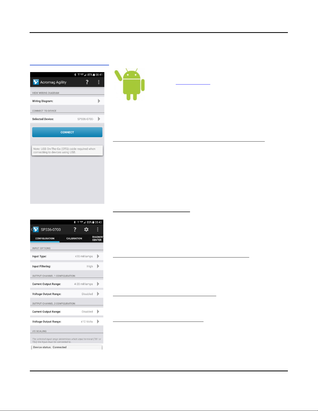
The initial connection screen of the app is shown at left. Once a device is
connected, the main portion of the app will launch. The screen is divided into three
tabs for this model. A short description of each tab follows.
Connection Screen Set up –DEVICE SELECT (First Connect to Unit Here)
•Select from connected transmitters by tapping the [Select Device] button. This
will bring up a list of attached devices. Select the desired device and tap the
Connect button to open the device.
•To view wiring diagrams of a transmitter, tap the [Wiring Diagram] button and
select the desired model. Swipe left or right to view more diagrams. No
connection is required to view the diagrams.
•Android requires user permission to access external hardware. If the Device
List displays “No Device Permission”, select this device and when prompted to
give permission to access the USB device, tap [OK].
Configuration Tab –CONFIGURE I/O
•Once connected, the app will automatically read your transmitter and display
its current configuration.
•Changing any option on this page will send the changes to the transmitter
instantly. The device status at the bottom of the page will report if the changes
were sent successfully.
Calibration Tab –(Calibrate the Input and/or Output if Needed)
•On screen instruction guides the set up to properly calibrate the transmitter.
After completing instructions, tap the [Calibrate] button.
•The device status at the bottom of the page will report if the calibration was
sent successfully.
Diagnostic Center Tab –(Verify Input operation)
•Select the polling indicator by tapping the [Indicator] button.
•Start polling by tapping the [Start Polling] button.
Utility Page –(Reboot or Restore Settings)
•Tap the [Gear] in the Action bar to access the Utility Page.
•You can tap the [Restore/Reset Factory] utility buttons to get out of trouble if
you ever misconfigure or improperly calibrate a transmitter.
Acromag, Inc. Tel: 248-295-0880
- 15 -
https://www.acromag.com
Model SP33X-0700
4-Wire DC I/V Signal Splitter w/USB
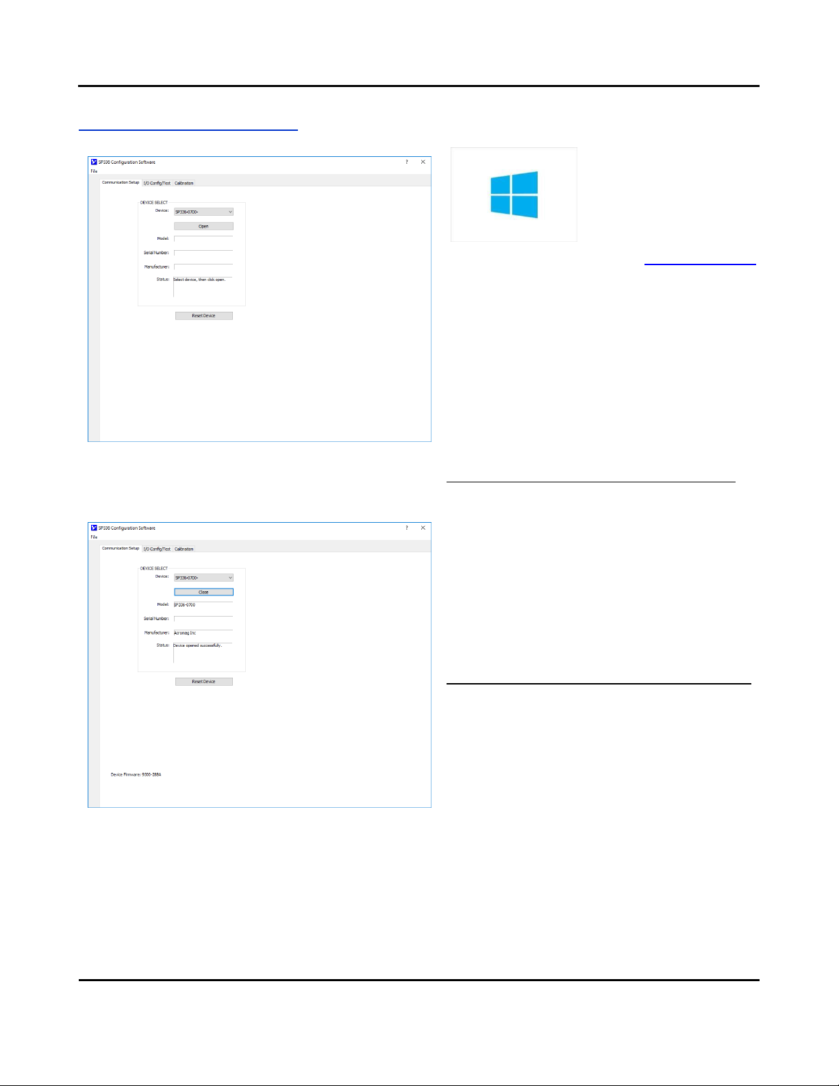
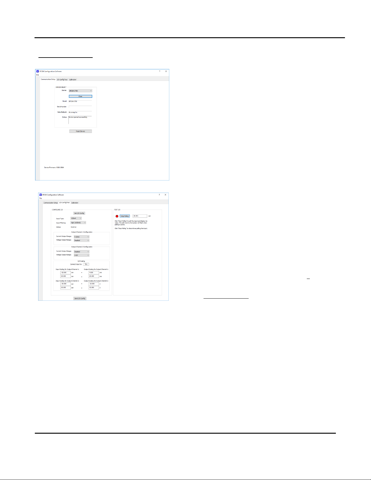
Quick Overview –Windows
Click “Open” to connect to the SP336-0700 and your
screen will like:
HELP –You can press F1 for Help on a selected or highlighted
field or control. You can also click the [?] button in the upper-
right hand corner of the screen and then click again to point
to a field or control to get a Help message pertaining to the
item you pointed to.
This transmitter can be
configured and calibrated via its
USB Configuration Software and
a USB connection to your
Windows PC or laptop. The USB
software can be downloaded
free of charge from our web site at www.acromag.com,
and included on a CDROM bundled with the
Configuration Kit TT-SIP (see Accessories section). For
this model, look for the program SP33XConfig.exe. This
software is compatible with v7 or later versions of the
Windows operating system.
The initial USB configuration software screen for this
model is shown at left. Configuration information is
divided across three separately tabbed pages as follows:
Communication Set up, I/O Config/Test, and Calibration.
A short description of each of these configuration pages
follows:
Communication Set up (First Connect to Unit Here)
•Select from connected transmitters and Open/Close
communication with them.
•Display the Model, Serial Number, and Manufacturer
of the connected transmitter and report the status
of communication with it.
This section is used to select a connected transmitter,
and open/close communication with it. Device
connection Status is also indicated here, along with the
connected transmitter’s ID info (Product Name/serial,
Manufacturer, & Serial Number).
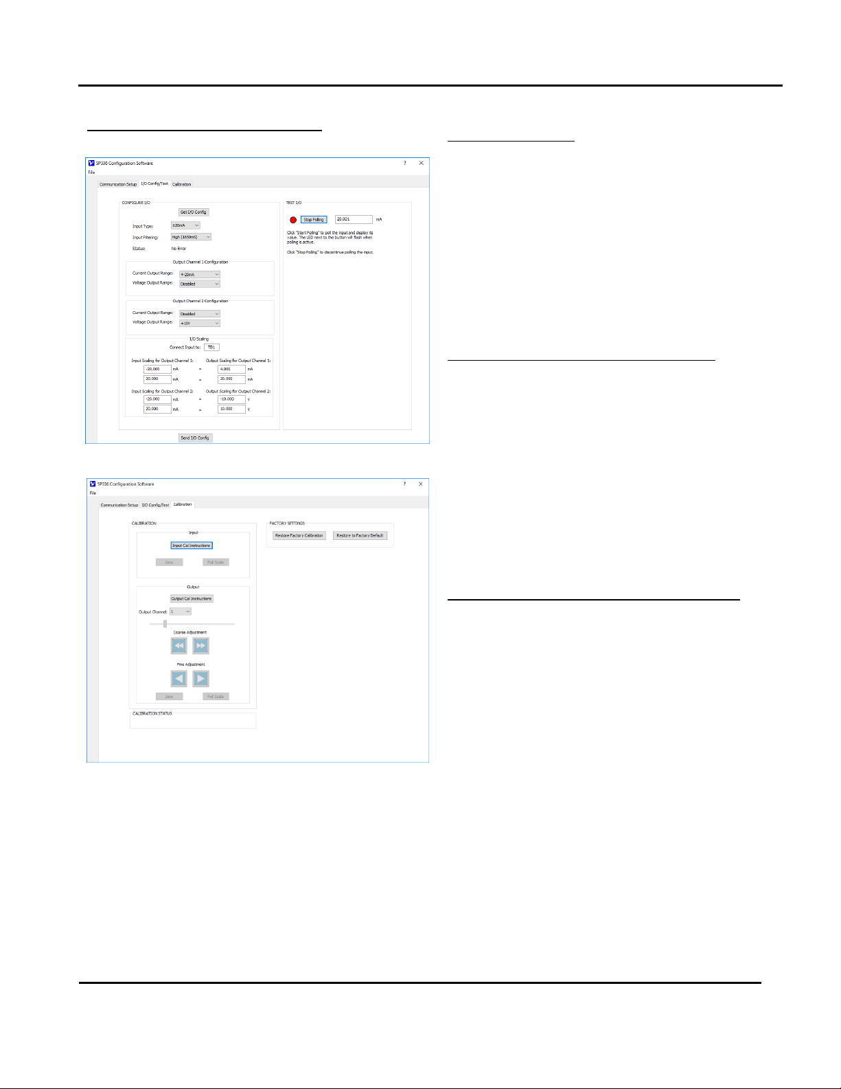
I/O Config/Test (Configure and/or Test the Unit Here)
•You can click the [Get I/O Config] button to retrieve
the I/O configuration of the currently connected
transmitter.
•Select the Input Range. You can select current
ranges ±20mA, 0-20mA, 4-20mA, 0-11.17mA, or
±1mA for current wired to TB1, or voltage ranges
±0.5V and 0-500mV for voltage wired to TB2.
•Set the level of digital filtering to High, Medium,
Low, or None (No digital filter). The corresponding
I/O response time varies with filter selection and is
indicated in parenthesis next to your selection.
•Set the Output Range to ±10V, ±5V, 0-5V, 0-10V,
±20mA, 0-20mA, or 4-20mA.
•View the unit’s configuration message status in the
Status field.
Acromag, Inc. Tel: 248-295-0880
- 16 -
https://www.acromag.com
Model SP33X-0700
4-Wire DC I/V Signal Splitter w/USB
Quick Overview –Windows...
HELP –You can press F1 for Help on a selected or highlighted
field or control. You can also click the [?] button in the upper-
right hand corner of the screen and then click again to point
to a field or control to get a Help message pertaining to the
item you pointed to.
I/O Config...continued
•Use the I/O Scaling fields to specify the specific input
range endpoints that are to correspond to the
output range zero and full-scale endpoints (some
over/under-range is included).
•Last, after making I/O changes, send your settings to
the unit by clicking the [Send I/O Config] button and
follow the on-screen prompts.
For detailed configuration and calibration procedures,
see the Operation Step-By-Step section of the Technical
Reference on page 18 of this manual.
Test I/O (Optional, Verify Unit Operation Here)
After making I/O configuration changes, you can use the
TEST I/O controls to start/stop polling the input channel
to check your input readings.
•Click the [Start Polling] button to periodically read
your input channel and validate its operation. Click
[Stop Polling] to stop polling the input channel.
Note the simulated red lamp to the left of the button
flashes slowly when the software is polling the input
channel. Stop polling before sending a configuration
or selecting another page.
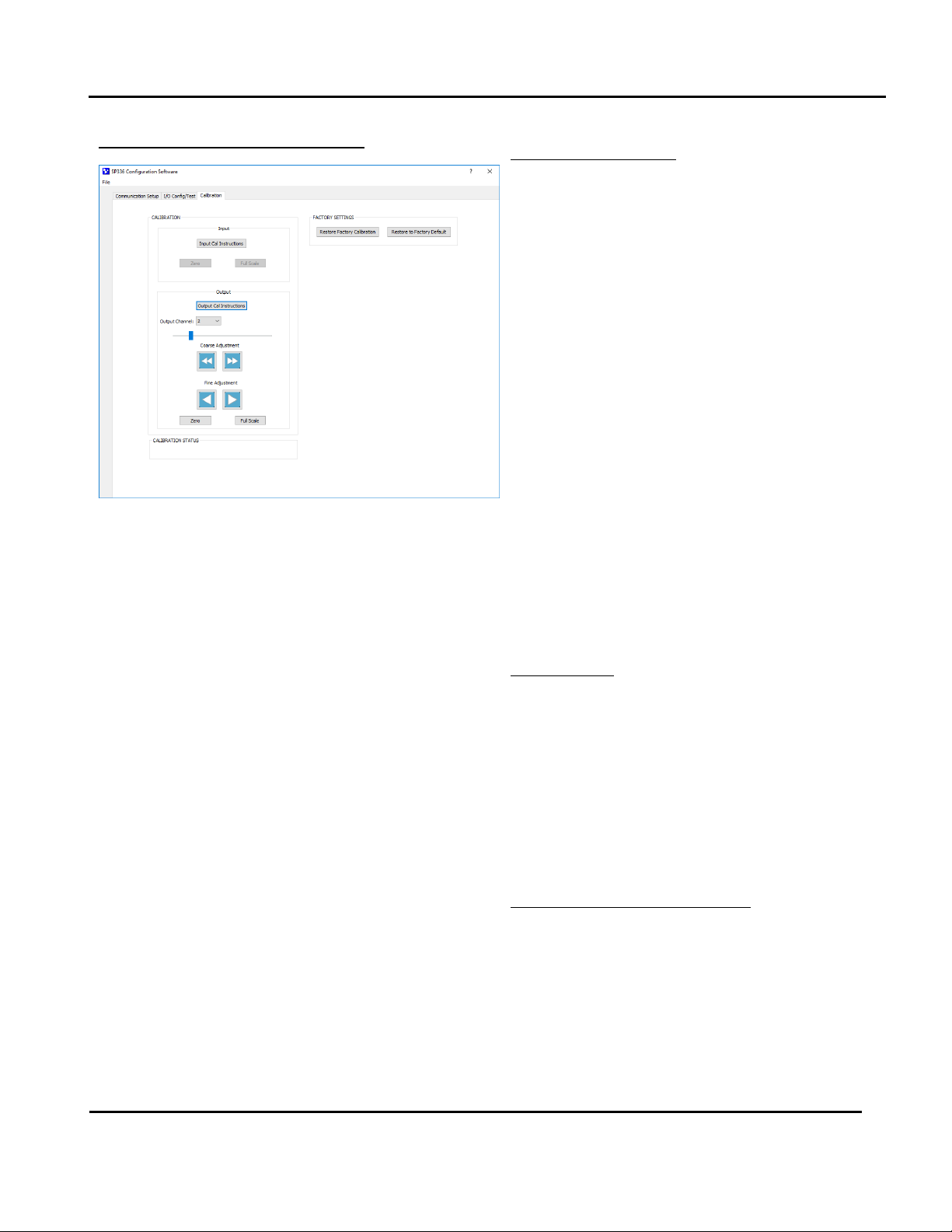
CALIBRATION (Calibrate Input or Output if Needed)
This unit has already been factory calibrated. If you
encounter excessive error, you can choose to click the
Calibration tab to display the Calibration control page
shown in the second screen at left.
To calibrate the Input or Output stage of this model,
simply click the respective “Cal Instructions” button and
follow the on-screen prompts.
Note that only nominal I/O ranges are used for
calibration, not your scaled I/O ranges. Always set the
input filter as desired before calibrating the input.
Acromag, Inc. Tel: 248-295-0880
- 17 -
https://www.acromag.com
Model SP33X-0700
4-Wire DC I/V Signal Splitter w/USB
Quick Overview –Windows...
CALIBRATION...continued
Input…
Before attempting calibration, first set the Input Range
to calibrate from the I/O Config/Test page and be sure to
click the [Send I/O Config] button. On the Calibration
page, click the [Input Cal Instructions] button to begin
input calibration.
When you click the [Zero] or [Full Scale] buttons of the
Input Calibration section, you will be prompted to apply
a specific current level at TB1, or voltage level at TB2,
depending on your selected input range. Once you have
applied this signal to the correct input terminals, click
the [OK] button of the prompt and follow the on-screen
instructions to complete input calibration.
Output…
Click the [Output Cal Instructions] button to begin
output calibration. You will be prompted to adjust the
input signal as required to drive the output to its precise
output range zero or full-scale level. Then once the
output is set to zero or full-scale, you simply click the
corresponding [Zero] or [Full-Scale] button of the
CALIBRATION - Output section to set the output range
zero or full-scale endpoint.
Factory Settings
(Use in Case of Trouble or for Sanitation Purposes)
•Restore a transmitter to its original factory
calibration.
•Restore a transmitter to its initial factory
configuration.
You can click the “Restore Factory” buttons if you ever
misconfigure or improperly calibrate a transmitter such
that its operation appears erratic, or for sanitation
purposes when decommissioning a module.
Calibration Status (Bottom of Screen)
•Displays communication status messages for the
calibration process.
The CALIBRATION STATUS message bar at the bottom of
the screen will display status messages relative to
calibration.

Acromag, Inc. Tel: 248-295-0880
- 18 -
https://www.acromag.com
Model SP33X-0700
4-Wire DC I/V Signal Splitter w/USB
TECHNICAL REFERENCE
OPERATION STEP-BY-STEP
Connections
This section will walk you through
the Connection-Configuration-
Calibration process step-by-step.
But before you attempt to
reconfigure or recalibrate this
transmitter, please make the
following electrical connections
Connect Input
Connect Output
Connect Power
Connect
PC/USB
Configure I/O
Note: Your input source, output meters, and load resistors (current outputs) must
be accurate beyond the unit specifications, or better than ±0.1%. A good rule of
thumb is that your equipment accuracy should be four times better than the rated
accuracy you are trying to achieve with this transmitter.
Calibration Connections:
1. Connect Input: Connect a precision current source to the TB1 input terminals
(SP336 only), or a precision voltage source to the TB1 or TB2 input terminals as
required for your input model/range. Your signal source must be adjustable to
the nominal input range zero and full-scale levels. Observe proper polarity.
For voltage input, use a voltage source with an output impedance of 100or
less. For best results, set the input filter as desired before calibrating an input.
2. Connect to One Output, Voltage or Current of Each Output Channel: Wire
output loads to the unit appropriate for either current or voltage, as required
by your application. You will need to measure output current or voltage
accurately to calibrate the output. You could connect a current meter in series
with the load to read the output current directly, or a digital volt meter in
parallel with the load to measure output voltage. Alternatively, you could
simply connect a voltmeter across a precision load resistor to accurately read
output current as a function of the IR voltage drop produced in the load
resistor (recommended for current outputs).
3. Connect Power: Wire 6-32VDC power to the unit at TB5 as shown in the
Electrical Connections section. Optionally, you may wire power to the bus
terminal as shown in the optional power connections drawing. But in either
case, never exceed 36VDC peak, or damage to the unit may result.
Apply power to the transmitter before connecting to USB. You will not be able
to configure or calibrate the unit without power also applied, as this device
does not draw power from its USB connection.
4. Connect to PC via USB: Connect the transmitter to the PC using the USB
isolator and cables provided in Configuration Kit TT-SIP (refer to Accessories).
You may omit the isolator only if you are using a battery powered laptop to
connect to the unit, or if your input source is not already grounded.
Now that you have made your connections and applied power, you can
execute the SP33XConfig.exe software for your model to begin configuration of
the unit (software is compatible with v7 or later versions of the Windows
operating system).
Acromag, Inc. Tel: 248-295-0880
- 19 -
https://www.acromag.com
Model SP33X-0700
4-Wire DC I/V Signal Splitter w/USB
Configuration
Note that you should already have power connected to the
transmitter at this point. This model does not utilize USB power and
you will not be able to configure, calibrate, or test the unit without
power applied.
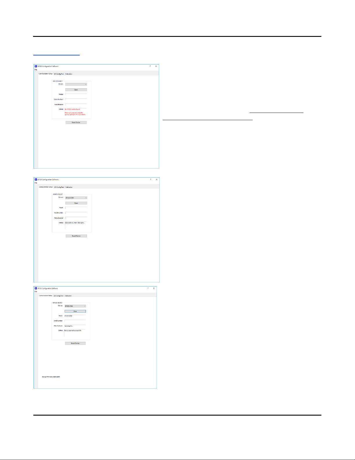
After executing the Acromag Configuration software for this model,
the screen shown at left will appear, if you have not already
connected to your transmitter via USB (note fields are blank under
these conditions).
Connect your PC to the unit via USB, and the unit’s model-serial
information will appear in the Device field as shown in the second
screen at left.
If you happen to be connected to more than one unit via a USB hub,
you can use the Device scroll field to select another unit, using the
serial information suffix of the Device Model number to discern one
unit from another.
Once you have selected a device, click the [Open] button to open
communication with the unit.
After clicking [Open], the selected unit’s Model, Serial Number,
Manufacturer, and connection status message will be displayed as
shown in the first screen on the next page.
TIP: Always Close a connection with one device before selecting
another device. Make sure you have the correct model software for
the model you are configuring.
Acromag, Inc. Tel: 248-295-0880
- 20 -
https://www.acromag.com
Model SP33X-0700
4-Wire DC I/V Signal Splitter w/USB
Configuration…
After you connect USB and “Open” communications with a unit,
the Status field indicates “Device opened successfully” as shown
in the screen at left.
At this point, you can click the “I/O Config/Test” tab to begin
configuring the unit, or optionally test its operation. The I/O
Config/Test screen is the second screen shown at left.
When you click the “I/O Config/Test” tab, the software retrieves
the unit’s current configuration and displays it like the second
screen shown at left.
IMPORTANT: Note that these models have two input points. For
the SP336, the first input is TB1 (upper terminal block of input
side) for DC current only, and its second input is TB2 (the lower
terminal block of the input side) for DC voltage only. For the
SP337 & SP338, both TB1 & TB2 are intended for different ranges
of DC voltage input. Your selected input range will determine
which terminal block you wire your input to. Only one input may
drive the output at one time.
If you are connected to a module, the initial I/O Config screen
represents the current configuration of the connected module
before making changes. Otherwise, if you have loaded the
configuration from a saved file, or have made changes to any
fields, you can click the [Get I/O Config] button at the top of the
screen to retrieve the connected module’s current configuration.
Note that if you make any changes to the selections indicated,
the only way to preserve your changes is to write them to the
device by clicking the [Send I/O Config] button after completing
your selections, or to save them to a file by clicking “File” in the
upper left-hand corner of the screen.
Select the Input Type/Range…
Input Range refers to the nominal input range. On the SP336, DC
current inputs are wired to TB1 and support ranges ±20mA, 0-
20mA, 4-20mA, 0-11.17mA, and ±1mA. DC voltage ranges are
wired to TB2 and support nominal ranges ±0.5V or 0-500mV. The
SP337 & SP338 support DC voltage ranges at TB1 and TB2.
Note that any input range you pick here can be rescaled to the
output, allowing you to use only a portion of the selected input
range to drive a current or voltage output, as desired. However,
resolution will decrease proportionally as you rescale the input
signal smaller than the nominal range. Each halving of the
nominal range will reduce resolution by 1 bit. This can also
magnify error, especially noticeable for very small input ranges
which degrade the signal-to-noise ratio of the input and
resolution of the analog-to-digital conversion.
This manual suits for next models
3
Table of contents
Other Acromag Media Converter manuals


