Acromag EIS-408FX-M User manual

EIS-408FX-M & EIS-408FX-S
8-Port Managed Industrial Ethernet Switch
(6x 10Base-T/100Base-TX and 2x 100Base-FX)
User’s Manual
ACROMAG INCORPORATED
Tel: (248)624-1541
30765 South Wixom Road
Fax: (248)624-9234
P.O. BOX 437
Wixom, MI 48393-7037 U.S.A.
Copyright 2005, Acromag, Inc., Printed in the USA.
Data and specifications are subject to change without notice.
8500-786-A05K000

Table of Contents
Chapter 1 Introduction........................................................................................................ 1-1
Overview.....................................................................................................1-1
Ethernet Switching Technology..................................................................1-1
Key Product Features.................................................................................1-3
Package Contents ......................................................................................1-3
Chapter 2 Hardware Installation......................................................................................... 2-1
Introduction.................................................................................................2-1
Panel Layout.............................................................................................2-1
Reset Button .............................................................................................2-2
LED Indicators ..........................................................................................2-2
DIP Switches.............................................................................................2-3
Connecting Input Power .............................................................................2-3
Connecting to the Output Relay..................................................................2-3
Connecting to the Ethernet Ports................................................................2-3
Connecting to the Fiber Ports.....................................................................2-5
DIN-Rail Mounting Installation....................................................................2-6
Wall-Mounting Installation...........................................................................2-7
Chapter 3 Web-based Management................................................................................... 3-1
Introduction.................................................................................................3-1
Preparation for Web Management..............................................................3-1
System Login..............................................................................................3-1
Configuration via the Web-based Management Interface ..........................3-2
Menu Bar Introduction ..............................................................................3-2
Configuring Your Switch............................................................................3-2
Chapter 4 Troubleshooting................................................................................................. 4-1
Power Connections.....................................................................................4-1
Incorrect Connections.................................................................................4-1
Faulty or Loose Cables.............................................................................4-2
Non-Standard Cables ...............................................................................4-2
Improper Network Design.........................................................................4-2
LED Indicators............................................................................................4-2
Appendix A Specifications.....................................................................................................A-1
Data and Specifications are subject to change without notice.
Windows® is a registered trademark of Microsoft Corporation.

1-1
1
1
Chapter 1 Introduction
Overview
Ethernet Switching Technology
Key Product Features
Package Contents
Installation Guide
Overview
The EIS-408FX-M and EIS-408FX-S are web-managed, industrial Ethernet rail switches that
have six 10/100MBaseTX ports, plus two 100BaseFX ports (multi-mode “-M” or single-mode “-S”
models), and are designed to operate under harsh environmental conditions. These switch
models also include advanced support for media redundancy and offer communication fail-over
times less than 300 milliseconds. These switch models also have a wide operating ambient
range and include redundant power inputs with reverse polarity protection. The unit includes a
DC-IN jack and may be optionally powered from an AC-DC wall transformer for Small
Office/Home Office (SOHO) applications. It is packaged in a rugged, IP-30 aluminum enclosure
for increased protection from extreme temperature, vibration, dust, and debris. This switch has
also passed several safety certifications to help ensure safe and reliable data transmission for
industrial applications.
In addition to supporting the Spanning Tree Protocol (STP) and Rapid Spanning Tree Protocol
(RSTP), this switch includes a proprietary redundant ring technology that allows it to manage a
media loop with other switches of the same type. A media loop is created when a message sent
out on one port is received by the same switch at another port (two message paths exist). This
switch is smart enough to temporarily disable the second path, holding it as a backup in case the
primary path fails. It also includes a normally closed alarm relay to signal a port failure (if
enabled). The switch will automatically fail-over to a secondary path within 300ms if the primary
path is lost.
These switches also support SC-type fiber connections in both single-mode and multi-mode
versions, useful for extending transmission distance. A web-based management interface
ensures easy operation and reconfiguration via a standard internet web browser.
Ethernet Switching Technology
To better understand the operation of an Ethernet switch, we need to first differentiate it from a
hub. An Ethernet hub (or repeater) is a device that is used to simply connect Ethernet nodes.
Any message at one hub port is repeated on all ports. That is, hubs forward data packets they
receive from a single station to all hub ports. As a result, all port devices connected to a single
hub will share the same bandwidth. Then as nodes are added to the network hub, they compete
for this finite amount of bandwidth and this can cause data collisions to occur, making network
determinism impossible to attain, especially on busy networks. Now determinism is a term that is
used to describe the ability to guaranty that a packet is sent or received in a finite and predictable
amount of time. The inherent lack of determinism is the main reason that traditional Ethernet had
problems being accepted for use in critical control applications, as most control systems have a
defined time requirement for packet transmission, typically less than 100ms.

1-2
Switches on the other hand, are intelligent devices used to more efficiently connect distributed
Ethernet nodes than a hub. Unlike a simple hub, a switch provides targeted data transfer, as it
will forward a data packet to a specific port or network segment, rather than to all ports, thus
freeing up bandwidth. The ability to target a packet to a specific port increases network
throughput and helps to eliminate the collisions that have historically made Ethernet
non-deterministic.
So we see that by targeting the data transfer between ports, switches act as intelligent repeaters
to increase network distances. In doing this, they actually split networks into separate collision
domains at each port. Thus, switches increase determinism by reducing collisions. Switches also
increase network bandwidth and throughput, as well as provide supplemental error checking on
data packets to help ensure the integrity of forwarded data. Each port of this switch functions just
like any other Ethernet device. It is able to receive and decode Ethernet frames, test for frame
integrity, plus assemble and transmit Ethernet frames.
With Ethernet, any device can try to send a data frame out at any time. If two devices happen to
send a data frame at the same time, then a collision may occur. The arbitration protocol for
carrier transmission access of the Ethernet network is called Carrier Sense Multiple Access with
Collision Detect (CSMA/CD). With CSMA/CD, each device will first sense whether the line is idle
and available for use. If it is, the device will begin to transmit its first frame. If another device also
tries to send a frame at the same time, then a collision occurs and both frames are discarded.
Each device then waits a random amount of time and retries its transmission until it is
successfully sent.
Unlike other Ethernet devices, such as an Ethernet host adapter or Network Interface Card (NIC),
the port of a switch does not require its own MAC address. During retransmission of a received
packet, the switch port will instead look like the originating device by having assumed its source
address. This is why the Ethernet collision domain is said to terminate at the switch port. That is,
a two-port switch will effectively break a network into two distinct data links or segments. An
eight port switch like the Acromag EIS-408FX can break a network into 8 distinct data links or
segments (also called collision domains). Since all Ethernet nodes are able to recognize the
occurrence of a collision, and since the detection of a collision is principal to the way Ethernet
arbitrates media access, large domains containing many nodes can become quite cumbersome.
Thus, using an Ethernet switch to subdivide a large network into separate collision domains will
certainly help to increase throughput.
The current tendency in critical industrial control applications is to connect one Ethernet device
per switch port. This will produce the most deterministic mode of operation as the switch can
then operate full-duplex, with no chance of collisions. This ensures determinism, helping critical
control applications to remain predictable and on-time.
Each port of a switch forwards data to another port based on the MAC address contained in the
received data packet/frame. In order to know which port to forward a data packet to, the switch
will learn and store the MAC addresses of every device it is connected to, along with the
associated port number. However, until the switch actually learns the port a particular address
resides at (the first packet), it forwards this traffic to all ports just like a hub. The switch will its
internal look-up table to quickly determine the location (port) of a node, establish a temporary
connection between itself and the node, then terminate the connection once a packet is
transferred. In this way, it increases network bandwidth and provides the network determinism
required for critical control applications.
This switch uses a store and forward algorithm to process Ethernet frames. That is, it first stores
the Ethernet frame and examines it for errors before forwarding it to its destination.Although this
method may seem to increase the forwarding time (latency) and possibly cause fragmentation, it
effectively reduces the occurrence of error frames and improves overall throughput. This is
particularly useful when there is heavy network traffic and or greater potential for noise and
interference.

1-3
The industry-wide shift from Ethernet hubs to Ethernet switches has dramatically boosted the
bandwidth of networks and helped to eliminate congestion problems inherent with the CSMA/CD
protocol (Carrier Sense Multiple Access with Collision Detection). Since a switch operates by
learning the location of addresses and forwarding messages directly, unnecessary traffic is
greatly reduced. It will use auto-negotiation to regulate the speed and duplex of each port based
on the capabilities of connected devices. These features combine with flow control allow a 100M
node to effectively communicate with a 10M node without losing data. Connecting one device
per switch port also allows two-way, simultaneous transmission to occur (full duplex), essentially
doubling the bandwidth. Further, by segmenting a collision domain in this way, the need for
non-deterministic carrier sensing (CSMA/CD) is eliminated. The utilization of a store-and-forward
switching algorithm allows each packet to be inspected, and corrupt or redundant data to be
filtered, further eliminating unnecessary traffic that often slows a network down.
Key Product Features
8-port, 10Base-T/100Base-TX/FX managed industrial switch
Supports IEEE 802.3 10Base-T, 802.3u 100Base-TX/100Base-FX
Non-blocking, store-and-forward switching architecture
1Mbits embedded buffer memory with 2K entry MAC address table
Web-based reconfiguration with easy-to-use GUI
Redundant Media Ring support with 300ms fail-over
Supports Spanning Tree Protocol (STP) and Rapid Spanning Tree Protocol (RSTP)
Provides redundant dual DC power inputs with reverse polarity protection and alarm
Provides an optional AC-DC wall transformer power input for SOHO applications
Includes an alarm relay to signal port break and/or power failure
RJ45 ports have automatic MDI/MDI-X crossover
Supports IEEE 802.3x flow control for full-duplex operation
Includes back pressure control for half-duplex operation
Supports broadcast packet filtering
Rugged aluminum case with IP30 rated protection
Versatile DIN-rail, surface, and wall-mountable design
Supports VLAN/QoS/IGMP Snooping
Supports Class of Service (COS)
Supports IGMP with query mode for multi media application
Supports SNTP
Supports port-based VLAN / 802.1Q Tag VLAN
Package Contents
One industrial web-managed Ethernet rail switch
One DIN-Rail clip (attached to the switch)
One wall mounting plate and six screws (separate accessory)
Documentation and Software CD
Quick Installation Guide
If any of the above items are missing or damaged, please contact your local sales representative
for replacement or repair.

2-1
2
2
Chapter 2 Hardware Installation
This chapter includes the following installation and configuration information:
Introduction
¾Panel Layout
¾Reset Button
¾LED Indicators
¾DIP Switches
Connecting to Input Power
Connecting to the Alarm Output Relay
Connecting to the Ethernet Ports
Connecting to the Fiber Ports
DIN-Rail Mounting Installation
Wall Mounting Installation
Introduction
Panel Layout
Front View
1 LED indicators (PWR, RM, PWR1, PWR2, FAULT).
2 DIP switches (to enable port alarms and designate redundant
Ring Master).
3 RJ-45 ports w/ integrated FDX/COL & LNK/ACT LED
indication.
4 Fiber ports (SC type connector).
5. Reset Button
Bottom View
At the bottom of this switch is a
ground screw and a 6-position plug-in
terminal block connector with two DC
power inputs and a relay connection.
There is also a DC-IN power jack for
connecting an optional AC-DC power
adapter (wall transformer type).

2-2
Reset Button
The reset button is located on the front panel just below the DIP switches and provides a quick
and easy way to restart and restore switch settings to their default values. To simply restart the
unit, press the reset button for 2 seconds and release. To restart and restore the switch to its
factory default settings, press the button and hold for 5 seconds and release.
Note that you must always restart a switch after setting its Ring Master DIP switch in order to
activate the new DIP switch setting or the redundant ring will not operate.
LED Indicators
These switch models have 5 diagnostic LED’s and 16 Port LED’s located on the front panel. The
following table describes the function of each LED indicator.
Status LED Status Description
Green Any Power is ON (PWR1, PWR2, or DC-IN).
PWR OFF No power is being supplied.
Green Power 1 is ON.
PWR 1 OFF No power 1 is being supplied.
Green Power 2 is ON.
PWR 2 OFF No power 2 is being supplied.
Green Indicates this switch is designated as the
redundant Ring Master.
R.M
OFF Indicates switch is NOT the Ring Master.
Yellow Power, RJ45, or fiber port failure has occurred.
FAULT OFF Normal operation (no power or port failure).
Port LED Status Description
Green A network device is detected.
Blinks This port is transmitting to, or receiving packets
from another transmitting device.
LNK/ACT
Fiber Ports 7 and 8 OFF No device is attached.
Yellow The port is operating in full-duplex mode.
Blinks A collision of packets has occurred.
FDX/COL
Fiber Ports 7 and 8 OFF The port is in half-duplex mode or no device is
attached.
Yellow The port is operating in full-duplex mode.
Blinking
Yellow A collision of packets has occurred.
OFF Port is in half-duplex mode or no device is
attached.
Green A network device is detected.
Blinking
Green Port is transmitting to, or receiving packets from
another transmitting device.
FDX/COL
Port Status
RJ45 Ports 1-6
LNK/ACT
OFF No device is attached.

2-3
DIP Switches
The DIP switches are used to set which switch in a redundant media ring is to be the Ring Master,
and to separately enable the port alarms.
DIP SWITCH Status Description
ON Set this switch to be the Ring Master.
R.M. OFF Set this switch to NOT be the Ring Master.
ON To enable the port break alarm at this port.
P1 to P8 OFF To disable the port break alarm at this port.
Notes (DIP Switches):
1. If the corresponding port alarm DIP switch is set ON, when that port connection fails, the
Fault LED will light up and the alarm relay contacts will close.
2. After you set a switch to be the Ring Master in a redundant media ring, you must restart this
switch to activate the settings (see Reset Button) or ring redundancy will not operate.
3. Only one switch in a media ring should have its Ring Master switch set to ON.
4. In order for a redundant ring to operate, all switches in the ring must be of the same type
(employ the same redundant ring method).
Connecting Input Power
IMPORTANT: It is good practice to turn off input and load power, and unplug the power terminal
block before making wire connections. Otherwise, your screwdriver blade can inadvertently short
your terminal connections to the grounded enclosure.
1. Insert the positive and negative wires of your DC supply into the V+ and V- contacts of the
terminal block connector. The acceptable wire range is 12 to 24 AWG.
2. Tighten the terminal screws to prevent the wires from coming loose.
3. OPTIONAL – DC IN: This switch has an additional power jack for the connection of AC-DC
power converters (wall-transformer type) designed for office use. Be sure that the output
voltage is within the required 12-48V DC range and of sufficient capacity to power the unit.
Refer to switch PWR LED to verify power via the DC-IN jack.
Note: If all three power inputs are connected (DC IN, PWR 1, PWR 2), the switch will be
powered from the highest connected voltage. The unit will not alarm for loss of DC IN power, the
alarm function only applies to loss of power at PWR1 or PWR2.
Connecting to the Output Relay
The alarm output relay contacts are in located at the two middle terminals of the power terminal
block, between PWR2 and PWR1 as shown in the figure below. These contacts are single-pole
single-throw (SPST) and are energized (open-circuited) for normal operation. These contacts
will close if the unit is not powered, or if either DC power 1 or power 2 fails, or if a port connection
fails (if that port alarm DIP switch is ON). The figure below gives an example of how the output
alarm relay operates.
Note: The relay contacts are energized (open) for normal operation and will close for fault
conditions. This contact does not supply any power and is rated up to 24V DC at 1A.

2-4
1. Connect to the SPST alarm relay terminals per your application. Insert your load wires and
tighten the alarm terminal screws to prevent the wires from coming loose. These contacts
are open for normal operation and close in alarm. Do not exceed 24V and 1A.
2. Verify that your load is wired to the center two terminals of this terminal block. After the
power relay is wired, replace this terminal block into its socket.
Connecting to the Ethernet Ports
This switch includes six RJ-45 ports with automatic MDI/MDI-X crossover, and automatic
10/100Mbps data rate sensing for 10Base-T or 100Base-TX connections. Automatic MDI/MDI-X
crossover allows you to connect to other switches, hubs, or workstations, without regard to using
straight-through or crossover cabling. The following figures depict the schematic diagram of
straight-through and crossover cabling. Note that crossover cables simply cross-connect the
transmit lines at each end to the receive lines at the opposite end.
Straight-through Cabling Schematic Crossover Cabling Schematic
Note that Ethernet cables use pins 1, 2, 3, and 6 of an 8-pin RJ45 connector. The signals of
these pins are converted by the automatic MDI-X function, as shown in the table below:

2-5
Pin MDI-X Signals MDI Signals
1 RD+ TD+
2 RD- TD-
3 TD+ RD+
6 TD- RD-
Connect one side of an Ethernet cable into any switch port and connect the other side to your
attached device. The green LNK LED will light up when the cable is correctly connected. Refer to
the LED Indicators section for descriptions of each LED indicator. Always make sure that the
cables between the switches and attached devices (e.g. switch, hub, or workstation) are less
than 100 meters (328 feet).
Two switches are now up-linked together. If we change the up-link port manually at this time, the
MAC address table will change as well. After the MAC address table changes, then the data can
be transmitted between these two switches. This period of time is called the MAC address table
aging time. The switch’s default aging time is 5 minutes, which means that if you manually
change the up-link port, you will need to wait up to 5 minutes before the data can be sent. If the
aging time is too short, the MAC address table will constantly refresh, resulting in excess
consumption of switch computing resources. For this reason, a longer aging time is
recommended.
Connecting to the Fiber Ports
The automatic MDI/MDI-X crossover function does not apply to fiber connections, as these must
be crossed over manually. To connect the fiber port on one switch to the fiber port of another
switch, simply cross-connect the transmit channel at each end to the receive channel at the
opposite end as illustrated in the figure below.
These models have two 100Base-FX ports with SC type connectors (in multi-mode and single
mode versions). Single-mode types have greater distance capability than multi-mode types, but
single mode cable is generally more expensive.
A fiber segment using single-mode cable must use 9/125 or 10/125 micrometer single-mode
fiber cables. For single-mode, the connection distance can be up to 30 km.
A fiber segment using multi-mode must use 50 or 62.5/125 micrometer multi-mode fiber cables.
For multi-mode, the connection distance can be up to 2 km.

2-6
DIN-Rail Mounting Installation
The DIN-Rail clip is attached to the rear of the switch via two screws. This clip may be removed
for surface or wall mounting. If the DIN-Rail clip is not already attached, follow these instructions
to attach the DIN-Rail clip.
1. Use the two screws provided to attach the DIN-Rail clip to the rear panel of the switch where
shown below (note that the spring side of the DIN clip is positioned at the top).
2. For flat surface or wall mounting, you can remove the DIN-Rail clip in similar fashion.
Follow these steps to mount the switch to the DIN-rail track.
1. Insert the upper end (spring side) of the DIN-rail clip onto the upper lip of the DIN-rail track as
shown below.
2. Push the bottom of the switch inward by tilting it downward until it snaps onto the track.
Check that the unit is firmly secured to the track.
3. To remove the Switch from the track, push downward on the unit to compress the spring,
and pull the bottom outward from the track to disengage the unit and lift it off the track.

2-7
Wall-Mounting Installation
Follow these steps to mount the unit to a wall or other flat surface.
1. Use a screwdriver to remove the two screws that secure the DIN-Rail clip to the back of the
switch.
2. Use a screwdriver to attach the wall-mounting plate to the rear panel of the switch using the
six screws provided. Tighten these screws to secure the switch to the wall-mounting plate.
3. Use the slotted holes at each corner of the wall-mounting plate to attach the unit to the wall
or other flat surface.
4. To remove the unit from the wall and from the wall-mounting plate, reverse steps 1-3.

3-1
3
3
Chapter 3 Web-based Management
This chapter includes the following information on how to configure and manage your switch via
a web-based interface:
Introduction
Preparation for Web Management
System Login
Configuration via the Web-based Management Interface
¾Menu Bar Introduction
¾Configuring Your Switch
Introduction
Embedded HTML web pages are stored in non-volatile memory within the switch. These pages
allow you to use a standard web-browser such as Microsoft Internet Explorer, or Mozila, to
configure and interrogate the switch from anywhere on the network.
The internal web-based management interface supports Internet Explorer 5.0 and Mozila 1.7.5
(including the FireFox version). These easy-to-use management screens are based on Java
applets to minimize the consumption of network bandwidth and increase your access speed.
Note: IE 5.0 or later versions do not allow Java applets to open sockets by default. Users have to
directly modify the browser settings to selectively enable Java applets to use network ports.
Preparation for Web Management
Before you attempt to use the embedded web interface to manage switch operation, verify that
the switch is properly installed on your network and that every PC on this network can access the
switch via the web browser.
1. Verify that your network interface card (NIC) is operational, and that your operating system
supports the TCP/IP protocol.
2. Wire DC power to the switch and connect your switch to your computer.
3. Make sure that the switch default IP address is 192.168.10.1.
4. Change your computer IP address to 192.168.10.2.
5. Switch to DOS command mode and ping 192.168.10.1 to verify a normal response time.
System Login
1. Launch the Internet Explorer web browser on the PC.
2. Type http:// followed by the IP address of your switch. Then press Enter.
3. The switch login screen will appear next.
4. Key in the user name and password. The default user name and password is admin.
5. Click Enter or OK, and the home page of the management interface will appear.
6. Once you actually enter the management interface, you should change the switch IP
address setting according to your network environment (consult your network administrator).
3-2
Configuration via the Web-based Management Interface
Menu Bar Introduction
Home Port Status Port
Statistics Port Control Switch
Settings Port
Mirroring VLAN
Configuration
IP
Configuration SNTP IP Security RSTP Redundant
Ring QoS IGMP
Security
Manager Configuration
Backup TFTP Update
Firmware Factory
Default Save
Configuration System
Reboot Rate Control
Home - The home page of this embedded web-based management interface.
Port Status - This section is to display the port status and applicable settings.
Port Statistics - This section is to display the switch port data flow statistics.
Port Control - This section is to configure the switch port settings.
Switch Settings - This section is to display the information of the switch system.
Port Mirroring - This section is to enable and configure port mirroring settings.
VLAN Configuration - This section is to enable and configure VLAN settings.
IP Configuration - This section is to set up the switch IP address.
SNTP - This section is to enable the network time server (Simple Network Time Protocol).
IP Security - This section configures the IP address for user access to the switch via the web.
RSTP - This section is to enable and configure Rapid Spanning Tree Protocol (RSTP).
Redundant Ring - This section is to enable and configure redundant ring settings.
QoS - This section is to enable and configure QoS (Quality of Service) settings.
IGMP - This section is to enable and configure the switch’s IGMP Snooping function.
Security Manager - This section is used to change the username & password for access to this
interface.
Configuration Backup - This section is to backup the switch settings to a file on your PC.
TFTP Update Firmware - This section is to use the TFTP utility to update the firmware of the
switch (this is only done when instructed to do so by the factory).
Factory Default - This section is to restore the factory default settings.
Save Configuration - This section is used to save the switch settings to non-volatile memory.
System Reboot - This section is used to reboot the switch.
Rate Control – This section is used to setup each port’s bandwidth rate & packet limitation type.
Configuring Your Switch
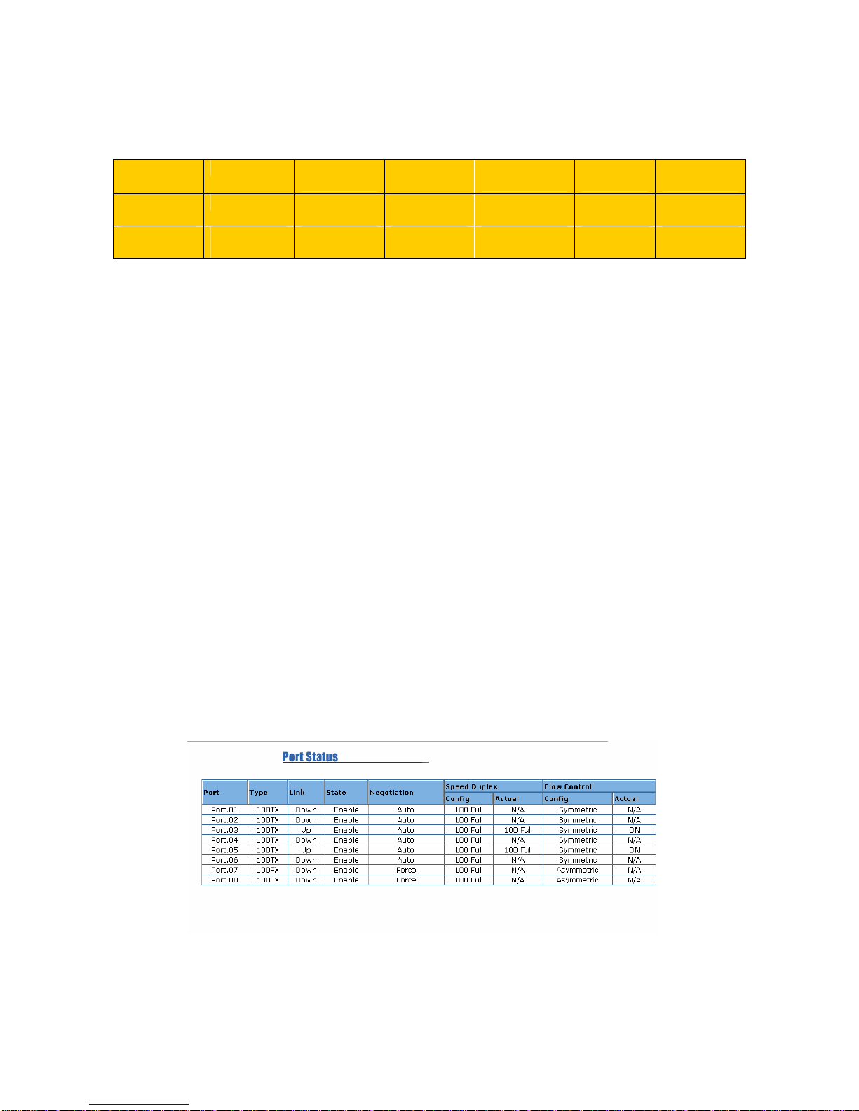
Port Status
This window allows you to view the status of each port as follows:
Port: Indicates the port number.
Type: Indicates the speed mode of the port (for example, 100TX means 100 Mbps).
Link: “Down” indicates that a connection is not established; “Up” indicates a connection has
been successfully established.
State: Indicates whether the port is Enabled or Disabled. A disconnection is also denoted as
“Disabled”.

3-3
Negotiation: “Auto” means that the switch will auto-negotiate the speed (automatically select
10M or 100M bps), and the transmission mode (full or half duplex), with the remote device. Force
means that the switch will run according to your own forced settings for speed and duplex.
Speed/Duplex: Configured and Actual - Refers to the port speed and duplex setting. The Config
column shows the configuration set up by you, while the Actual column shows the actual speed
of the port.
Flow Control: Configured and Actual – “Symmetric” specifies that you need to activate the flow
control function of the remote network device in order to let the flow control of that corresponding
port of the switch to work. “Asymmetric” indicates that you don’t need to activate the flow control
function of the remote network device. The flow control of that corresponding port on the switch
will work anyway.
Single Port Status
To get the single port status screen, you can click directly on any port number displayed at left to
see port-specific information for that port and similar to that listed below:
Port Statistics
In this section, you can view operation statistics for each port. Click Clear to reinitialize and clear
any counts.
Port Control
Simply select the port you want to configure and you will be able to view the current status and
settings of the selected port, and make changes to port settings as required.

3-4
In the State column, you can enable or disable control over this port.
In Negotiation column, you can configure the auto-negotiation mode to Auto to enable
automatic negotiation, or Force (to directly specify the speed/duplex on this port).
In the Speed column, you can configure the speed of this port.
In the Duplex column, you can configure the full-duplex or half-duplex mode of this port.
In Flow Control column, “Symmetric” means that you need to activate the flow control function
of the remote network device in order to allow the flow control mechanism of the corresponding
port of the switch to work. “Asymmetric” means that you don’t need to activate the flow control
function of the remote network device, as the flow control of the corresponding port of the switch
will work anyway.
Once you finish your configuration, click Apply to apply your settings.
Note: Remember to click on the Save Configuration button to save your settings. Otherwise the
settings you made will be lost when the switch is powered off.
Switch Settings
With the Switch Settings screen, you can assign a system name, location, and brief description.
You can also view stored information.
System Name: You can use this field to assign a name to the switch.
System Location: You can use this field to specify the switch’s physical location.
System Description: You can attach a brief description to the switch here.
Firmware Version: Displays the firmware version installed in this switch.
Kernel Version: Displays the kernel version in this switch.
Hardware Version: Displays the hardware version of this switch.
MAC Address: Displays the unique hardware address (MAC address) assigned by the
manufacturer (the default setting).
Once you finish your configuration, click Apply to apply your settings.
Note: Always remember to select Save Configuration to save your settings. Otherwise, the
settings you made will be lost when the switch is powered OFF.

3-5
Port Mirroring
Port mirroring (also called port spanning) is a tool that allows you to mirror the traffic from one or
more ports onto another port, without disrupting the flow of traffic on the original port. Any traffic
that goes into or out of the monitored port(s) will be duplicated at the mirror port. This traffic can
then be analyzed at the mirror port using a monitoring device. A network administrator will
typically utilize this tool for diagnostics or debugging, or to fend off attacks.
Port Mirroring State: Select the mirroring mode - Disable, Rx, Tx, or Both Rx & Tx.
Analysis Port: This is the mirror port. You can analyze the traffic of all the monitored ports at this
port without affecting the flow of traffic on the port(s) being monitored. A network administrator
would typically connect a LAN analyzer or Netxray device to this port.
Monitor Port(s): These are the ports you want to monitor. The traffic of all monitored ports will
be copied to the mirror ports. You can choose a single port, or any combination of ports, but you
can only monitor them in one mirror mode. To disable this function, set the monitor port to None.
Once you finish your configuration, click on Apply to apply your settings.
Note: Always remember to select Save Configuration to save your settings. Otherwise, the
settings you made will be lost when the switch is powered off.
VLAN Configuration
A Virtual LAN (VLAN) is a “logical” grouping of nodes for the purpose of limiting a broadcast
domain to specific members of a group, but without physically grouping the members together.
That is, a VLAN allows you to isolate network traffic so that only members of the VLAN would
receive traffic from the same VLAN members. Basically, creating a VLAN from a switch is the
logical equivalent of physically reconnecting a group of network devices to another Layer 2
switch, without actually disconnecting these devices from their original switch.
This switch supports both port-based and 802.1Q (tagged-based) VLAN’s. The VLAN Operation
Mode is set to “disable” by default.

3-6
Port-based VLAN
The packets that a switch receives and identifies as belonging to a port-based VLAN are
forwarded only over the ports assigned to that VLAN. Ports not selected as belonging to a VLAN
are treated as if they belong to another single VLAN. Port based VLAN’s are limited to the ports
of a single switch and do not allow membership to cross boundaries into other switches, as with
tag-based VLAN’s. Further, if a port-based VLAN is enabled, any VLAN-tagging will be ignored.
1. Click Add to add a new VLAN group.
2. Enter a VLAN group name, group IP, and then select the members for this VLAN group.
3. Click on Apply to adopt the settings.
4. Next, you will see your VLAN group displayed.
5. If the group list is longer than one page, you can click Next Page to view other VLAN groups.
6. Use the Delete button to delete any unwanted VLAN’s.
7. Use the Edit button to modify the existing VLAN’s.
Note: Always remember to select Save Configuration to save your settings. Otherwise, the
settings you made will be lost when the switch is powered off.
Because the port-based VLAN is defined on the switch itself and does not use information
contained in the packet frame to define its membership, it is restricted to ports of the same switch.
Effectively, only the switch itself knows the architecture of a port-based VLAN, while the
segments connected to the switch ports have no way of knowing the VLAN definition even exists.
This is the key difference between port and tag based Virtual LAN’s.
802.1Q VLAN
This tag-based VLAN is an IEEE 802.1Q standard, which allows VLAN’s to be created across
different switches (see Figure 1). IEEE 802.1Q tag-based VLAN’s make use of VLAN control
information stored in a VLAN header attached to IEEE 802.3 packet frames. This tag contains a
VLAN Identifier (VID) that indicates which VLAN a frame belongs to. Since a switch only has to
check a frame’s tag, without the need to dissect the contents of the frame, this also saves a lot of
computing resources within the switch.
Figure.1 Tagged VLAN

3-7
Basic
1. Click on Add button to add a new tag-based VLAN.

3-8
2. Group Name: You can name your new VLAN grouping here. The Group Name is simply a
reference for the network administrator to help differentiate VLAN’s.
3. VLAN ID: Enter a VLAN ID here (12 bits). Enter any value from 2 to 4094 (default value is 1).
The VLAN ID is used by the switches to identify the different VLAN’s and this is encoded into
the IEEE 802.1q frame.
4. Select specific ports of this switch to be included in the VLAN from the available ports box.
Click Add to add ports to the VLAN, or Remove to remove ports from the VLAN. Then click
Next to continue. Please note that each VLAN will require a “tagged port”. Different VLAN’s
use these tagged ports to communicate with one another.
5. Here you can specify the egress (outgoing) VLAN frames to be Tagged frames or Untagged
frames. Click on Apply to apply your settings.
Tag: Indicates that egress/outgoing frames are to be VLAN tagged.
Untag: Indicates that egress/outgoing frames are not VLAN tagged.
Port VID
Port VLAN ID (PVID): Enter the port VLAN ID here. The Port VID (PVID) allows the switches
to identify which port belongs to which VLAN. To keep things simple, it is recommended that
you set the Port VID equivalent to the VLAN ID’s. You can skip tagged ports, as tagged ports
do not need Port VLAN ID’s.
To reset to default values, click Default.
Once you finish your configuration, click Apply to apply your settings.
Note: Always remember to select Save Configuration to save your settings. Otherwise, the
settings you made will be lost when the switch is powered off.
This manual suits for next models
1
Table of contents
Other Acromag Network Router manuals


