bintec elmeg bintec 4Ge-LE User manual

bintec 4Ge-LE
Installation Manual
Copyright© bintec Dm571-I Version 7.2 11/2018 bintec elmeg
bintec elmeg Manual
bintec 4Ge-LE 1

Legal Notice
Warranty
This publication is subject to change.
bintec elmeg offers no warranty whatsoever for information contained in this manual.
bintec elmeg is not liable for any direct, indirect, collateral, consequential or any other damage connected to the de-
livery, supply or use of this manual.
Manual bintec elmeg
2bintec 4Ge-LE

Table of Contents
I RelatedDocuments................................. 1
Chapter1 AboutThisGuide.................................. 2
1.1 SupportedDevices................................... 2
1.2 Who should read this manual? . . . . . . . . . . . . . . . . . . . . . . . . . . . . . . 2
1.3 When should this manual be read? . . . . . . . . . . . . . . . . . . . . . . . . . . . . 2
1.4 Whatisinthismanual?................................. 2
1.5 Whatisnotinthismanual? ............................... 2
1.6 How is the information organized? . . . . . . . . . . . . . . . . . . . . . . . . . . . . 2
1.7 TechnicalSupport ................................... 2
Chapter2 bintec4Ge-LE ................................... 4
2.1 Characteristics..................................... 4
2.1.1 PowerSupply..................................... 4
2.1.2 HardwareMonitoring.................................. 4
Chapter 3 Components and Power Supply . . . . . . . . . . . . . . . . . . . . . . . . . . 5
3.1 Components...................................... 5
3.1.1 FrontPanel...................................... 5
3.1.2 RearPanel ...................................... 5
3.1.3 SidePanels...................................... 6
3.1.4 UndersidePanel.................................... 6
3.1.5 TopPanel(LEDs).................................... 7
3.2 Assembly....................................... 8
3.2.1 Mountinginrack.................................... 8
3.2.2 Standalone ...................................... 8
3.2.3 Wallmounting..................................... 8
3.2.4 Ceilingmounting................................... 10
3.2.5 Installing a DIN rail mount accessory (Optional). . . . . . . . . . . . . . . . . . . . . . 10
3.3 PowerSource.................................... 11
3.3.1 ExternalPowerSource................................ 11
3.3.2 PoE......................................... 12
3.3.3 Connecting to the power source . . . . . . . . . . . . . . . . . . . . . . . . . . . . 12
3.3.4 Connect....................................... 12
3.3.5 Disconnect...................................... 13
3.4 RESETButton.................................... 13
3.4.1 Rebootingthedevice................................. 13
bintec elmeg Table of Contents
bintec 4Ge-LE i

3.4.2 DefaultConfiguration................................. 13
3.5 Connectingdata................................... 14
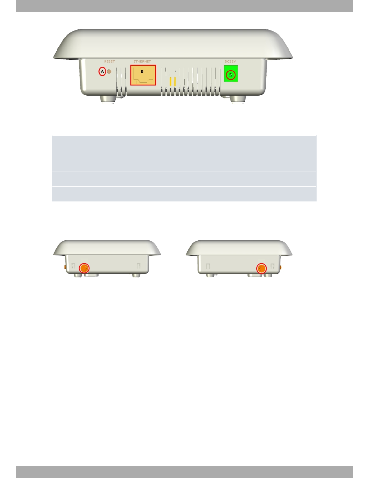
3.5.1 ETHERNETConnection................................ 14
3.5.2 Connecting the WWAN Antenna . . . . . . . . . . . . . . . . . . . . . . . . . . . . 14
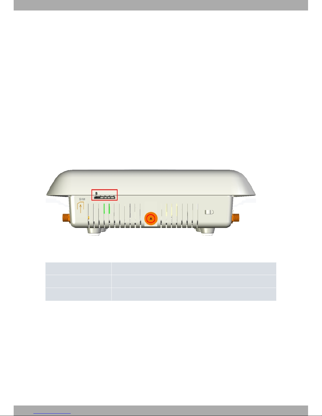
3.6 InstallingtheSIMcard................................. 15
Chapter4 Compliance.................................... 17
4.1 ManufacturerInformation............................... 17
4.2 SafetyWarnings................................... 20
4.3 WEEEInformation.................................. 21
4.4 REACH....................................... 21
4.5 EC Declaration of Conformity. . . . . . . . . . . . . . . . . . . . . . . . . . . . . . 21
4.6 CEMarking..................................... 21
4.7 NationalRestrictions................................. 22
4.8 OperatingFrequency................................. 22
4.9 FCCStatement.................................... 22
4.9.1 Federal Communications Commission Interference . . . . . . . . . . . . . . . . . . . . 22
4.10 ICStatement..................................... 22
4.10.1 CAN ICES-3 (B)/NMB-3(B). . . . . . . . . . . . . . . . . . . . . . . . . . . . . . . 22
Appendix A Technical Information . . . . . . . . . . . . . . . . . . . . . . . . . . . . . . 24
A.1 Troubleshooting................................... 24
A.2 Updatingthesoftware................................. 24
A.3 Connectors ..................................... 24
A.3.1 LANConnector.................................... 25
A.3.2 WWAN Connector (female) . . . . . . . . . . . . . . . . . . . . . . . . . . . . . . 25
A.3.3 PowerSupplyConnector ............................... 25
A.4 TechnicalSpecifications................................ 25
A.4.1 HardwareArchitecture................................. 25
A.4.2 LANInterface .................................... 26
A.4.3 WirelessWANInterface................................ 26
A.4.4 PowerSupply.................................... 26
A.4.5 ExternalPowerSupply ................................ 26
A.4.6 Dimensionsandweight................................ 26
A.4.7 Environmental Specifications . . . . . . . . . . . . . . . . . . . . . . . . . . . . . . 27
AppendixB RadioInformation................................. 28
B.1 WWANSpecifications................................. 28
Table of Contents bintec elmeg
ii bintec 4Ge-LE

I Related Documents
bintec Dm748-I Software Updating
bintec elmeg Related Documents
bintec 4Ge-LE 1

Chapter 1 About This Guide
This is the installation guide for the bintec 4Ge-LE router. It contains information on how to correctly install this
device in a working environment.
1.1 Supported Devices
The information included in this installation guide only applies to the bintec 4Ge-LE router.
1.2 Who should read this manual?
This manual should be read by the support personnel who need to configure, maintain and monitor the device.
1.3 When should this manual be read?
Read this guide as soon as you are ready to familiarize yourself with the device and its components.
This manual will help you understand your new device in greater depth.
1.4 What is in this manual?
This installation guide contains the following information:
• Description of the available features in the bintec 4Ge-LE.
• Technical specifications.
• Power supply requirements.
• Elements you can connect to the device while it is running.
• Installation and removal procedures for modules and power supplies.
• Description of the device LEDs and the connectors.
• Troubleshooting.
1.5 What is not in this manual?
This manual does not contain information regarding the device software or its configuration. For information on how
to configure this device, please see the relevant protocol manuals, to be found on the bintec website: ht-
tp://www.bintec-elmeg.com.
1.6 How is the information organized?
Each chapter focuses on a specific part of the hardware and its components. All descriptive, technical specifications
and information on a component can be found in the relevant chapter.
1.7 Technical Support
bintec elmeg offers a technical support service. Device software can be upgraded on a regular basis for maintenance
purposes and for new features.
Contact information:
Web: http://www.bintec-elmeg.com
Tel. Nº: +49 - 911 - 9673 0
1 About This Guide bintec elmeg
2bintec 4Ge-LE

Fax: +49 - 911 - 688 0725
Email: support@bintec-elmeg.com
bintec elmeg 1 About This Guide
bintec 4Ge-LE 3

Chapter 2 bintec 4Ge-LE
2.1 Characteristics
2.1.1 Power Supply
For further information on the power supply for the bintec 4Ge-LE, please see Components and Power Supply on
page 5 under section Power Source on page 11.
2.1.2 Hardware Monitoring
The bintec 4Ge-LE router hardware is monitored through the LEDs panel, which provides visual information on what
is happening in the device. The LEDs indicate the state of the hardware components, if there is connectivity, data
flow, etc.
For further information on the LEDs panel, please see Components on page 5 in the following chapter.
2 bintec 4Ge-LE bintec elmeg
4bintec 4Ge-LE

Chapter 3 Components and Power Supply
The following chapter provides detailed information on the chassis of the bintec 4Ge-LE router and its components.
This information includes:
• Components.
• Information on assembly.
• Power supply.
• RESET button.
• Data connection.
• SIM card installation.
3.1 Components
3.1.1 Front Panel
The following figure shows the front panel. Here you can see the slot to insert the SIM card and one of the WWAN
antenna connectors.
Fig. 1: Front Panel
The front panel elements are as follows:
Front panel elements table
Item Description
A WWAN antenna for the bintec 4Ge-LE.
B Slot for the SIM card.
3.1.2 Rear Panel
The following figure shows the rear panel. Here you can see all the connectors for the bintec 4Ge-LE.
bintec elmeg 3 Components and Power Supply
bintec 4Ge-LE 5

Fig. 2: Rear panel
The following table provides information on each connector as well as a description:
Rear panel elements table
Item Description
A RESET. Reset button. For further information on how the reset button operates,
please see RESET Button on page 13 in this chapter.
B ETHERNET. Gigabit Ethernet.
C Power source connection (PSU).
3.1.3 Side Panels
Two WWAN antennas are located on the side panels, one on either side.
Fig. 3: Right hand side panel and Fig. 4: Left hand side panel
3.1.4 Underside Panel
The following elements can be found on the underside panel:
3 Components and Power Supply bintec elmeg
6bintec 4Ge-LE

Fig. 4: Underside panel
The following table contains details on the underside panel's significant elements.
Underside panel elements table
Item Description
A Slots for wall mount.
B Rubber feet.
C Perforations to install a DIN rail mount. (Optional.)
3.1.5 Top Panel (LEDs)
The LEDs panel provides information on the state of the components (whether they are active or not) and on the net-
work activity.
Fig. 5: LEDs Panel
bintec elmeg 3 Components and Power Supply
bintec 4Ge-LE 7

The LEDs for the bintec 4Ge-LE are shown in Figure 6. The table below contains a description of them:
LEDs table
LED Status Description
LAN Tricolor Green -> connected. Blinking: con-
nection data activity.
Amber -> blinking: auto-test.
Red -> disconnected.
PWR Monochrome green Device ON/OFF. This lights up when
connected to the power source.
W Tricolor Off -> system stopped.
Red -> interface is unavailable be-
cause it is installing, it is not enabled
(shutdown) or due to auto-test failure.
Yellow -> idle.
• Rapid blinking. It has not registered
in the network or the quality is in-
sufficient.
• Slow blinking. GSM connection
(GPRS).
• Steady. WCDMA (UMTS/HSDPA)
connection.
Green -> connected. Blinking: con-
nection data activity.
3.2 Assembly
3.2.1 Mounting in rack
The bintec 4Ge-LE cannot be mounted in a rack. However, there are other types of mounting.
3.2.2 Standalone
The bintec 4Ge-LE can be placed as a standalone device on a flat, stable surface.
Make sure that there is enough space around the router for ventilation purposes and that the electricity cables can
reach it.
3.2.3 Wall mounting
The bintec 4Ge-LE can be mounted on the wall.
There are two slots on the underside of the device, which are used to fix it to the wall. You can see this in Underside
Panel on page 6.
We recommend the following accessories for wall mounting, valid for solid wall and Gypsum board (plaster) wall:
• 2 screws: [Coach Screw Head 90 Degrees. 3.5x30].
3 Components and Power Supply bintec elmeg
8bintec 4Ge-LE

Fig. 6: Screw
• 2 wall anchors: [White Striated Wall Anchor. 8mm Diameter].
Fig. 7: Wall anchor
Warning
The screws must go into a wall stud (wood) or a wall anchor of the appropriate type for the wall. Screws
into drywall are not strong enough to mount the router.
Fig. 8: Wall-mounting features
The above figure shows the wall-mounting features on the bintec 4Ge-LE.
1 Wall screws 2 8.8 cm (3.46 inches)
3 Chassis mounting holes (on
the underside)
4 Router chassis
5 Mounting surface
To mount the router on a wall or another surface, follow these steps:
Procedure
bintec elmeg 3 Components and Power Supply
bintec 4Ge-LE 9

Step 1 Install the two screws (3.5x30) horizontally apart on a wall or any other vertical surface.
The screws should protrude 0.6 cm (0.25 inch) from the surface of the wall.
Warning
If you install the screws in drywall, use hollow-wall anchors (8 mm – 5/16 inch) to secure the screws. If
the screws are not properly anchored, the strain of the cables connected to the router back panel could
pull the router from the wall.
Step 2 Hang the router on the screws. This is the appropriate position for safe use. (See Fig. 8 on page 9)
Note
- The accessories to mount the device on a wall are not provided in the package and have to be ac-
quired separately.
- The accessories must be properly adapted to the kind of wall in place and must be chosen to ensure
that they can support the weight of the device.
3.2.4 Ceiling mounting
To attach the bintec 4Ge-LE device to the ceiling, use the appropriate support (not included and must be ordered
separately).
Fig. 9: Ceiling mounting support
3.2.5 Installing a DIN rail mount accessory (Optional)
Router packaging may contain a DIN rail mount kit, which can be attached to the router to place it in various posi-
tions.
3 Components and Power Supply bintec elmeg
10 bintec 4Ge-LE

The kit contains 2 screws to adjust the rail accessory on the underside of the device, as shown in the following figure:
Fig. 10: DIN rail mount adapter
3.3 Power Source
The bintec 4Ge-LE is powered though an external AC/DC source or through an Ethernet cable (if it complies with
the POE 802.3af standard).
Warning
The equipment must be used with the power supply provided by the manufacturer.
Workplace Conditions. Main Characteristics
• Avoid humid and/or dusty locations.
• Direct exposure to sunlight, as well as to other heat sources, should be avoided. The device should not be placed
amongst papers, magazines or other elements that could hinder natural air circulation.
• The device should not be placed very close to strong electromagnetic fields such as speakers, engines, etc.
• Knocks and/or strong vibrations should be avoided during transport, operation and storage.
Warning
The electric current in power cables, telephone lines and communication cables is dangerous. To pre-
vent electric shocks, before installing, handling or opening the equipment covers, connect and discon-
nect the cables following the steps set forth in Connect on page 12 andDisconnect on page 13.
3.3.1 External Power Source
To connect the power supply to the device, please follow the steps outlined in If the Ethernet cable isn’t PoE on page 12
.
To avoid electric shocks, residual current circulation and other unwanted effects, also affecting communications, the
following is recommended:
bintec elmeg 3 Components and Power Supply
bintec 4Ge-LE 11

Warning
All interconnected communication devices should be plugged to THE SAME GROUNDED POWER
OUTLET, which should at the same time be of good quality (lower than 10 ohms).
Whether the workplace is provided with an uninterrupted power supply system (UPS), regulated supply
or it is independent from the rest (such as lighting, etc.); it is highly recommended that all data devices
should be connected to the same power source. This will avoid operating and premature aging prob-
lems of drivers and other components.
3.3.2 PoE
Fig. 11: Diagram to connect the PoE adapter to the router
The bintec 4Ge-LE device can be powered through an Ethernet cable if the latter complies with the POE 802.3aF
standard. The ETHERNET port is enabled for this.
To connect the Ethernet cable with PoE power to the router, please carry out the steps outlined in If the Ethernet
cable is PoE on page 13.
Figure 11 provides detail on how to connect the PoE injector to the device.
3.3.3 Connecting to the power source
3.3.4 Connect
3.3.4.1 If the Ethernet cable isn’t PoE
• Make sure the router’s power supply switch is in the OFF position (0).
• Ensure that the power supply is NOT connected to either the electricity or the router.
• Connect all data cables.
• Connect the power supply cable to the device.
• Connect the power supply cable to the electricity supply.
• Set the router’s power supply switch to the ON position (1).
3 Components and Power Supply bintec elmeg
12 bintec 4Ge-LE

3.3.4.2 If the Ethernet cable is PoE
• Check that the Ethernet cable that is going to be used for power is NOT connected to the router.
• Make sure that the router’s power supply switch is in the OFF position (0).
• Ensure that the power supply is NOT connected to the electricity supply.
• Connect all data cables.
• If you need redundant power, connect the power supply to the device.
• If you need redundant power, connect the power supply to the electricity supply.
• Connect the Ethernet cable.
• Put the router’s power supply switch in the ON position (1).
3.3.5 Disconnect
3.3.5.1 If the Ethernet cable isn’t PoE
• Make sure the router’s power supply switch is in the OFF position (0).
• Disconnect the power supply from the electricity supply.
• Disconnect the power supply from the router.
• Disconnect the data cables.
3.3.5.2 If the Ethernet cable is PoE
• Disconnect the Ethernet cable.
• Make sure the router’s power supply switch is in the OFF position (0).
• Disconnect the power supply from the electricity supply.
• Disconnect the data cables.
3.4 RESET Button
The different features of the RST button are described below.
3.4.1 Rebooting the device
Once the device is operating normally, if you press the RST button, it will restart.
3.4.2 Default Configuration
The RST button allows you to boot the device with its default configuration through the following steps:
• With the device switched off, maintain the RESET button pressed and it will switch on.
• The POWER LED (green) will light up and the W LED will begin to blink. This blinking will continue for 10 seconds.
• For the device to boot with the default configuration, release the RESET button while the W LED is blinking (i.e. be-
fore the 10 second period expires).
Once the default configuration is running, you need to know what type of license the device has. Depending on the li-
cense, the device will operate as:
• Router: If you have a router license, the device will behave as a router. In this case, the default configuration estab-
lishes the following access IP address and the mask:
IP address: 192.168.1.1
IP mask: 255.255.255.0
• 4Ge: If you have a 4Ge license, the device will have a special configuration. Please see manual bintec Dm592-I -
bintec elmeg 3 Components and Power Supply
bintec 4Ge-LE 13

bintec 4Ge-LE User Manual for further information on its configuration and how to access the device.
To find out what type of license you have, execute a ping to IP address 192.168.1.1. The device, previously con-
figured with the default configuration and correctly connected through an Ethernet cable, will respond to the ping in-
dicating whether you are dealing with a router or a 4Ge.
Note
Some devices leave the factory with customized settings for a client. This personalization means that
the device may have a different default configuration from the one shown above.
3.5 Connecting data
The bintec 4Ge-LE has the following data connections.
3.5.1 ETHERNET Connection
The bintec 4Ge-LE incorporates an Ethernet 10/100/1000 BaseT Switch port with automatic MDI/MDIX.
Fig. 12: Ethernet Port
3.5.2 Connecting the WWAN Antenna
The bintec 4Ge-LE has three connectors to connect WWAN antennas. To assemble and dismantle the antennas,
simply screw them into the connectors labeled Cell (located on the front panel of the router).
The installation of these antennas in the bintec 4Ge-LE is essential to improve the quality of the signal received and
transmitted by the cellular model.
Note
To obtain a good quality performance, the bintec 4Ge-LE device should always have the WWAN an-
tennas installed.
Some cellular telephony technologies use the antenna diversity technique to improve the quality of the signal re-
ceived (HSUPA, CDMA EV-DO, etc.). Consequently, the bintec 4Ge-LE incorporates various WWAN connectors.
Fig. 13: WWAN connectors seen from the front panel
When the antennas are not directly connected to the router but installed through extension cords, the minimum dis-
tance between the two of them must be 7 cm. The maximum recommended distance between the two is 25 cm.
To achieve an optimum performance, the radio frequency accessories installed (antennas and cables) should be
those recommended by bintec.
3 Components and Power Supply bintec elmeg
14 bintec 4Ge-LE

bintec has a series of accessories (90º mount antennas, antennas for exterior installation, antennas for ceiling install-
ation, extension cables, etc.) that allow you to install the devices in different locations.
3.5.2.1 Placing the Antenna
The orientation of the bintec 4Ge-LE device and its location with respect to other wireless and radiation devices
(such as communication devices, personal computers, etc.) can significantly influence device performance.
The bintec 4Ge-LE device transmits and receives. Performance is also affected by environmental factors (such as
distance between the device and the base station), physical obstacles and other interferences caused by radiofre-
quencies (RF).
For optimum coverage, follow these steps:
• Whenever possible, place the antenna where there are no physical obstacles. Obstacles between the antenna and
the base station degrade the wireless signal. Place the antenna above ground level facing the nearest base sta-
tion.
• The density of materials also affects antennas. Place them away from walls, metal screens, mirrors, etc.
• Do not place the antenna near columns, which may throw shadows and reduce the coverage area.
• Keep the antenna away from metal ducts such as canalization, air-conditioning.
• Please bear in mind that other wireless devices such as telephones, microwaves, etc., can temporarily interfere
with the quality of the radio signal.
• We do not recommend installing antennas near, or between, racks containing communication devices, computers,
etc. Use an extension cable and place the device outside.
The following recommendations are applicable to all wireless devices:
• Do not touch or move the antenna while the device is transmitting or receiving.
• When the antenna is transmitting, do not touch any equipment that contains devices that radiate very close to, or
touching, any exposed part of the body (particularly face and eyes).
• Do not install the device in areas where the atmosphere is potentially explosive.
• Wireless devices can cause interferences with other devices. Do not use the device in environments where medic-
al equipment is installed.
• •To ensure compliance with the R&TTE 1999/5/EC norm, the device must be at least 1.5 cm away from a human
body when operating.
3.6 Installing the SIM card
A SIM card needs to be inserted in the bintec 4Ge-LE so the WWAN interface operates correctly. The router is
equipped with an external tray for SIM cards.
When inserting the SIM card, make sure you are protected against electrostatic discharges (ESD).
Warning
Do not touch the SIM card connector.
Fig. 14: Slot to insert the SIM card
Procedure:
bintec elmeg 3 Components and Power Supply
bintec 4Ge-LE 15

• Place the router as shown in the figure above.
• To insert the SIM card, follow the instructions shown on the bintec 4Ge-LE.
• Press it until it is fully inserted.
• To extract it, press it again and remove it.
3 Components and Power Supply bintec elmeg
16 bintec 4Ge-LE
Table of contents
Other bintec elmeg Network Router manuals

bintec elmeg
bintec elmeg RM3000 User manual

bintec elmeg
bintec elmeg W2022ax User manual

bintec elmeg
bintec elmeg RS123 User manual

bintec elmeg
bintec elmeg RM7000 User manual

bintec elmeg
bintec elmeg RXM7000 User manual

bintec elmeg
bintec elmeg H2 Automotive+ User manual

bintec elmeg
bintec elmeg RM3000 User manual

bintec elmeg
bintec elmeg RS300 Series User manual

bintec elmeg
bintec elmeg be.IP swift User manual

bintec elmeg
bintec elmeg be.IP swift User manual