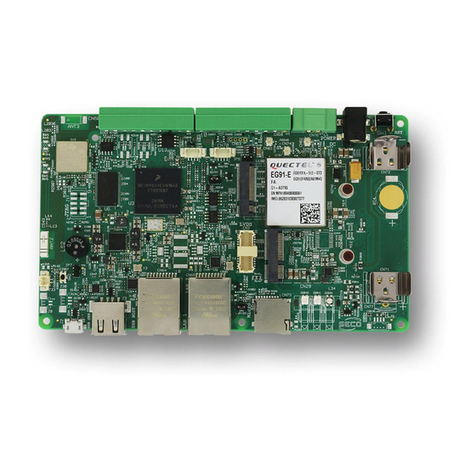
Acrosser Technology AR-B1684VSL2 User manual

~ Page i ~
AR-B1684VSL2/ VSL/ VL2/ VL
SOCKET 370 PENTIUM III GRADE CPU CARD
WITH VGA/LAN/SCSI
Operation Manual
Version 1.3

~ Page ii ~
COPYRIGHT NOTICE
This operation manual is expected to assist both Embedded Computer manufacturers and users in installing
and setting up the system. The information contained in this document is subject to change without any
notice.
This document is copyrighted, 2000, by Acrosser Technology Co., Ltd. All rights are reserved. No part of
this manual may be reproduced, transmitted, transcribed, stored in a retrieval system, or translated into any
language or computer language, in any form or any means, electronic, mechanical, magnetic, optical,
chemical, manual or other means without the prior written permission of original manufacturer.
Acrosser Technology assumes no responsibility or warranty with respect to the content in this manual and
specifically disclaims any implied warranty of merchantability or fitness for any particular purpose.
Furthermore, Acrosser Technology reserves the rights to make improvements to the products described in
this manual at any times without notice. Such revisions will be posted on the Internet
(WWW.ACROSSER.COM) as soon as possible.
Possession, use, or copy of the software described in this publication is authorized only pursuant to a valid
written license from Acrosser or an authorized sub licensor.
ACKNOWLEDGEMENTS
All other trademarks and registered trademarks mentioned herein are the property of their respective
owners.

~ Page iii ~
1. INTRODUCTION ......................................................................................................................................... 1
1-1. ABOUT THIS MANUAL ........................................................................................................................... 2
1-2. SYSTEM SPECIFICATION...................................................................................................................... 3
1-3. SAFETY PRECAUTIONS........................................................................................................................ 4
2. HARDWARE CONFIGURATION................................................................................................................ 5
2-1. JUMPER & CONNECTOR QUICK REFERENCE TABLE ...................................................................... 6
2-2. COMPONENT LOCATIONS.................................................................................................................... 7
2-3. HOW TO SET JUMPERS........................................................................................................................ 7
2-4. SYSTEM CLOCK SELECT AND CPU SETTING (J3)............................................................................. 8
2-5. DOC MEMORY MAPPING (J7)............................................................................................................... 8
2-6. COM1 CONNECTOR (COMA)................................................................................................................ 8
2-7. COM2 CONNECTOR (COMB)................................................................................................................ 9
2-8. PS2 KB (KM1).......................................................................................................................................... 9
2-9. EXTERNAL KEYBOARD & MOUSE CONNECTOR (KM2).................................................................... 9
2-10. RESET SWITCH (RST)....................................................................................................................... 10
2-11. HDD LED Header (HDL)...................................................................................................................... 10
2-12. POWER LED & KEYLOCK CONNECTOR (PLKL) ............................................................................. 10
2-13. IR CONNECTOR (IR).......................................................................................................................... 10
2-14. FLOPPY DISK DRIVE CONNECTOR (FDD) ...................................................................................... 11
2-15. HARD DISK DRIVE CONNECTOR (IDE1, IDE2)................................................................................ 12
2-16. SPEAKER/BUZZER (SPK).................................................................................................................. 12
2-17. ETHERNET RJ-45 CONNECTOR (LAN1).......................................................................................... 13
2-18. VGA CRT CONNECTOR (CRT).......................................................................................................... 13
2-19. WATCHDOG CONNECTOR (J1)........................................................................................................ 13
2-20. SCSI LED Header (J2)......................................................................................................................... 13
2-21. PRINTER CONNECTOR (LPT)........................................................................................................... 14
2-22. CPU & SYSTEM FAN POWER CONNECTOR (FAN1, J8) ................................................................ 14
2-23. POWER ON CONNECTOR FOR ATX POWER SUPPLY (PSW)...................................................... 14
2-24. POWER CONTROL CONNECTOR (ATX).......................................................................................... 14
2-25. UNIVERSAL SERIAL BUS CONNECTOR (USB1, USB2).................................................................. 16
2-26. CLEAR CMOS FUNCTION (J5).......................................................................................................... 16
2-27. DOC SOCKET (J6).............................................................................................................................. 16
2-28. TOUCH SCREEN CONNECTOR (T.S.).............................................................................................. 16
2-29. SCSI CONNECTOR ENABLED/DISABLED (JP1, JP2)...................................................................... 17
2-30. CPLD CONTROL CONNECTOR (J9)................................................................................................. 17
2-31. MEMORY INSTALLING....................................................................................................................... 18
3. SOFTWARE UTILITIES ............................................................................................................................ 19
3-1. UTILITY DISK FILE................................................................................................................................ 20
3-2. SETUP................................................................................................................................................... 20
3-3. WATCHDOG TIMER CONFIGURATION.............................................................................................. 21
4. AMI BIOS SETUP...................................................................................................................................... 22
4-1. BIOS SETUP OVERVIEW..................................................................................................................... 23
4-2. STANDARD CMOS SETUP.................................................................................................................. 24
4-3. ADVANCED CMOS SETUP.................................................................................................................. 25
4-4. ADVANCED CHIPSET SETUP ............................................................................................................. 28
4-5. POWER MANAGEMENT ...................................................................................................................... 30
4-6. PCI/PLUG AND PLAY ........................................................................................................................... 32
4-7. PERIPHERAL SETUP........................................................................................................................... 34
4-8. AUTO-DETECT HARD DISKS.............................................................................................................. 35
4-9. PASSWORD SETTING......................................................................................................................... 35
4-10. SETTING THE PASSWORD............................................................................................................... 35
4-11. PASSWORD CHECKING.................................................................................................................... 35
4-12. LOAD DEFAULT SETTING................................................................................................................. 35
4-13. BIOS EXIT ........................................................................................................................................... 36
4-14. BIOS UPDATE..................................................................................................................................... 37
APPENDIX A................................................................................................................................................. 38
A-1. ISA BUS PIN ASSIGNMENT................................................................................................................. 39
A-2. PICMG BUS PIN ASSIGNMENT........................................................................................................... 40
APPENDIX B................................................................................................................................................. 41
B-1. INTERRUPT MAP................................................................................................................................. 42

~ Page iv ~
B-2. RTC & CMOS RAM MAP...................................................................................................................... 43
B-3. TIMER & DMA CHANNELS MAP.......................................................................................................... 44
B-4. I/O & MEMORY MAP ............................................................................................................................ 45
APPENDIX C................................................................................................................................................. 46
TROUBLE SHOOTING................................................................................................................................. 46

~ Page 1 ~
1. INTRODUCTION
This chapter describes:
! About This Manual
! System Specifications
! Safety precautions
! Experienced users can skip to chapter 2 on page 5 for Quick Start.

~ Page 2 ~
1-1. ABOUT THIS MANUAL
Thanks for purchasing our AR-B1684 serial ---Socket 370 Pentium III Grade CPU Card with VGA / LAN /
SCSI, fully PC / AT compatible. This manual contains five chapters. By following the instructions herein, you
can easily use AR-B1684 CPU board.
AR-B1684 serial CPU card include AR-B1684VSL2, AR-B1684VSL, AR-B1684VL2 and AR-B1684VL. The
list below indicates the different.
AR-B1684 serial doesn’t keyboard control function. That’s because VT82C686B sourth bridge doesn’t
provide this function.
AR-B1684VSL2: On-board VGA, on-board dual 10/100 base Ethernet and on-board one two-channels
Ultra160 SCSI.
AR-B1684VSL: On-board VGA, on-board single 10/100 base Ethernet and on-board one two-channels
Ultra160 SCSI.
AR-B1684VL2: On-board VGA, on-board dual 10/100 base Ethernet.
AR-B1684VL: On-board VGA, on-board single 10/100 base Ethernet.
The contents of this manual are base on AR-B1684VSL2.
Chapter 1 Introduction
This chapter notifies you how to avoid the damages against this CPU Card as well as describes the
background of this manual and the specification of AR-B1684..
Chapter 2 Hardware Configuration
This chapter outlines the components' locations and their functions. From this part, you can find how to set
jumper and configure this card, as you need.
Chapter 3 Software Utilities
Helpful information about the proper installations of the VGA, LAN, SCSI and the Watchdog-timer function
are provided in this chapter.
Chapter 4 AMI BIOS Setup
This chapter indicates you how to set up the BIOS configurations.
Appendix A Expansion Bus
This section introduces you the expansion bus for ISA BUS and PICMG.
Appendix B Technical Summary
This section gives you the information about the Technical maps.
Appendix C Trouble Shooting
This section outlines the errors might occur and some solutions are suggested.

~ Page 3 ~
1-2. SYSTEM SPECIFICATION
CPU:
Supports 333~1GHz Socket 370 Celeron / Coppermine Pentium III grade CPU
CHIPSET:
VIA VT8604 (ProSavage PL133)
RAM MEMORY:
Supports 3 168-pin DIMM (PC-133 SDRAM) sockets, 768Mb max.
CACHE SIZE:
Internal 128KB L2 cache inside the CPU.
ETHERNET:
Use dual RT8139Cs chipset, support 10/100M Base T with RJ-45 connectors built-in LEDs.
SCSI:
Use SYMBIOS53C1010-33 or equivalent, supports two-channel Ultra-Wide SCSI III with 160MB transfer
rate and two 68-pin SCSI connectors.
SUPER I/O:
2 PCI IDE---with two 2.54 mm 40-pin connectors. (Support up to ATA-100)
1 FDC---with 2.54mm 34 -pin connector.
1 Parallel--- with 2.54 mm 26-pin connector. Supports SPP/EPP/ECP mode.
1 RS-232C-COM port 1 with DB9 connector located at bracket.
1 RS-232C/IrDA/Touch Screen –COM port 2.
IrDA use 2.54mm 5-pin header.
Touch Screen uses 2.0mm 3-pin JST connector.
BIOS:
AMI flash BIOS (256KB, including VGA/SCSI BIOS) Supports utility program for easy to update new version
of BIOS.
KEYBOARD/MOUSE:
PS/2 compatible with 2.0mm 6-pin JST connector and 6-pin mini-DIN connector located at bracket.
BUS INTERFACE:
PICMG -ISA
VGA DISPLAY:
S3 ProSavage AGP 4X VGA with display memory shared with system memory (2MB~32MB).
CRT-with HDB 15-pin connector located at bracket.
WATCHDOG:
System independent watchdog timer
SYSTEM POWER REQUIREMENT:
+5V-5.0A max. & +12V-1.0A max. (Based on 500 MHz CPU).
USB:
Built-in 4 ports USB interface with USB socket at bracket
RTC:
Chipset supports ACPI Function.

~ Page 4 ~
SPEAKER:
Supports on-board buzzer and external speaker. (With 2.5mm 4-pin header).
FLASH DISK:
Supports 1 DiskOnChip Socket 144MB.
H/W MONITORING:
Built-in (Wilnbond WB83782) hardware monitoring chipset.
HEADERS:
2-pin Reset, hard disk LED, and power/watchdog LEDs.
3-pin CPU cooling fan and Chassis cooling fan.
BUS DRIVER CAP:
High driver for 32 TTL level loads (max.)
CPU SP:
Separated Vcore and Vio.
CE DESIGN-IN:
Add EMI components to COM ports, Parallel port, CRT, USB, Keyboard, and PS/2 mouse.
PC BOARD:
6 layers, EMI considered, especially in switching power layout.
BOARD DIMENSION:
Compact size 338.6mm x 121.9mm(13.33" x 4.80")
1-3. SAFETY PRECAUTIONS
Follow the messages hereinafter to protect your systems from damage on all occasions.
Touch a grounded metal object to discharge the static electricity in your body (or ideally, wear a grounded
wrist strap)
Stay safe from the electric shock. Don‘t touch any components of this card when the card is on. Always
switch off power when the system is not in use.
Disconnect power when changing any hardware devices. For instance, when you connect a jumper or install
any cards, a surge of power may damage the electronic components or the whole system.

~ Page 5 ~
2. HARDWARE CONFIGURATION
Four parts are included:
! Jumper & Connector Quick Reference Table
! Components’ Locations
! Configuration and Jumper settings
! Connector Pin Assignments

~ Page 6 ~
2-1. JUMPER & CONNECTOR QUICK REFERENCE TABLE
SWITCH & JUMPER:
System Clock Select.....................................................................J3
DOC Memory Mapping.................................................................J7
Clear CMOS Function ..................................................................J4
CONNECTOR:
ON AR-B1684:
COM1 Connector ........................................................................COMA
COM2 Connector ........................................................................COMB
PS/2 Connector ..........................................................................KM1
Reset Switch ...............................................................................RST
Floppy Disk Drive Connector ......................................................FDD
Hard Disk Drive Connector .........................................................IDE1, IDE2
Hard Disk Drive LED Connector .................................................HDL
Power LED & KeyLock Connector ..............................................PLKL
Ethernet RJ-45 Connector ..........................................................LAN1
External Speaker Connector .......................................................SPK
Printer Connector ........................................................................LPT
System Fan Power Connector ....................................................J8
SCSI Connector ..........................................................................SCSIA, SCSIB
CPU Fan Power Connector ........................................................FAN1
VGA Connector ...........................................................................CRT
IR Connector ...............................................................................IR
Touch Screen Connector ............................................................T.S.
Power on connector for ATX Supply ...........................................ATX
Power Control Connector ...........................................................PSW
External Keyboard & Mouse Connector ......................................KM2
Watchdog LED Connector ..........................................................J1
Universal Serial Bus Connector ..................................................USB1
Memory Installing ........................................................................DIMM1, DIMM2, DIMM3
Disk-On-Chip Socket ..................................................................J6
ON AR-B9460:
Universal Serial Bus Connector ..................................................USB1, USB2
PS/2 Mouse Connector ...............................................................KM1
Ethernet RJ-45 Connector ..........................................................LAN1

~ Page 7 ~
2-2. COMPONENT LOCATIONS
AR-B1684 Connector, Jumper and Component Locations
DIMM3 SCSIA
SCSIB
U24
KM1
CRT
LAN1
COMA
DIMM1
DIMM2
J6
CN1
IDE1
IDE2
FDD
LPT
COMB
CN2
RST SPK HDL
J1
PLKL
FAN1
IR
J7
J5
J3
J8
PSW
ATX
KM2
JP1
JP2
T.C.
1
2
7
8
J2
AR-B9460 Connector, Jumper and Component Locations
CN2
USB1 USB2
LAN2
KM1
CN1
2-3. HOW TO SET JUMPERS
A jumper consists of two or three metal pins with a plastic base mounted on the card, and a small plastic
cap (with a metal contact inside) to connect the pins, so you can set up your hardware configuration by
"open"or close the pins. The jumper can be combined into sets, which called jumper blocks. When the
jumpers are all in the block, you have to put them together to set up the hardware configuration. The figure
below shows how it looks.
2 PIN 3 PIN
CAP
JUMPERS AND CAP
If a jumper has three pins, for example, labeled PIN1, PIN2, and PIN3, you can either connect PIN1 & PIN2
to create one setting and shorting or connect PIN2 & PIN3 to create another setting. The jumper setting
rules are applied throughout this manual.

~ Page 8 ~
2-4. SYSTEM CLOCK SELECT AND CPU SETTING (J3)
System clock is automatically detected by BIOS.
1
28
7
PIN 1-2 PIN 3-4 PIN 5-6 PIN 7.8
AUTO ON ON OFF OFF
133MHz OFF OFF OFF OFF
100MHz OFF OFF OFF ON
66MHz OFF OFF ON ON
2-5. DOC MEMORY MAPPING (J7)
1
28
7
J7 1-2 3-4 5-6 7-8
D000H ON OFF OFF OFF
D200H OFF ON OFF OFF
D400H OFF OFF ON OFF
D600H OFF OFF OFF ON
2-6. COM1 CONNECTOR (COMA)
COMA: COM1 Connector, DB9 male connector
51
10
6
1: DCD
2: RX
3: TX
4: DTR
5: GND
6: DSR
7: RTS
8: CTS
9: RI
(Factory Default)
(Factory Default)

~ Page 9 ~
2-7. COM2 CONNECTOR (COMB)
COMB: COM2 Connector
The COMB Connector assignments are as follows:
1
210
9
PIN ASSIGNMENT
1 DCD
2 RX
3 TX
4 DTR
5 GND
6 DSR
7 RTS
8 CTS
9 RI
10 NC
2-8. PS2 KB (KM1)
DIN: PS2 Connector
The PS2 connector can support Keyboard & Mouse.
The pin assignments for PS2 Connector are as follows:
12
34
5
6
PIN ASSIGNMENT
1 KBDATA
2 MSDATA
3 GND
4 Vcc
5 KBCLK
6 MSCLK
2-9. EXTERNAL KEYBOARD & MOUSE CONNECTOR (KM2)
EXPS2: External PS2 Connector
The pin assignments are as follows:
PIN ASSIGNMENT
1 KBDATA
2 MSDATA
3 GND
4 Vcc
5 KBCLK
6 MSCLK

~ Page 10 ~
2-10. RESET SWITCH (RST)
1. RS
2. GND
2-11. HDD LED Header (HDL)
1. VCC
2. HD LED
2-12. POWER LED & KEYLOCK CONNECTOR (PLKL)
AR-B1684 serial doesn’t keyboard control function. That’s because VT82C686B sourth bridge
doesn’t provide this function.
1. PWLED
2. X
3. GND
4. KLOCK
5. GND
2-13. IR CONNECTOR (IR)
1. +5V
2. NC
3. RX
4. GND
5. TX

~ Page 11 ~
2-14. FLOPPY DISK DRIVE CONNECTOR (FDD)
FDD: Floppy Disk Drive Connector
You can use a 34-pin daisy-chain cable to connect a two-FDD. One end of this cable is to attach the
FDD on the board and the other one is to attach the two-FDD.
The pin assignments are as follows:
1
234
33
PIN ASSIGNMENT PIN ASSIGNMENT
1 GND 2 DRVDEN0
3 GND 4 NC
5 GND 6 DRVDEN1
7 GND 8 INDEX
9 GND 10 MTR0
11 GND 12 DRV1
13 GND 14 DRV0
15 GND 16 MTR1
17 GND 18 DIR
19 GND 20 STEP
21 GND 22 WDATA
23 GND 24 WGATE
25 GND 26 TRK0
27 GND 28 WRPRT
29 GND 30 RDATA
31 GND 32 SEL
33 GND 34 DSKCHG

~ Page 12 ~
2-15. HARD DISK DRIVE CONNECTOR (IDE1, IDE2)
IDE1: Hard Disk Drive Connector (IDE1, IDE2)
The AR-B1684 possesses two HDD connectors, IDE1 and IDE2. The pin assignments are as
follows:
1
240
39
2-16. SPEAKER/BUZZER (SPK)
1. VCC
2. NC
3. BUZZER
4. SPKR
3-4 on (Factory Default Setting)
Enable Internal Buzzer
PIN SIGNAL PIN SIGNAL
1 -RESET 2 GROUND
3 DATA 7 4 DATA 8
5 DATA 6 6 DATA 9
7 DATA 5 8 DATA 10
9 DATA 4 10 DATA 11
11 DATA 3 12 DATA 12
13 DATA 2 14 DATA 13
15 DATA 1 16 DATA 14
17 DATA 0 18 DATA 15
19 GROUND 20 NOT USED
21 IDEDRQA 22 GROUND
23 -LOW A 24 GROUND
25 -LOR A 26 GROUND
27 -CHRDY A 28 GROUND
29 DACKA 30 GROUND
31 -IRQ 14 32 NOT USED
33 SA 1 34 NOT USED
35 SA 0 36 SA2
37 CS 0 38 SA1
39 HD LED A 40 NOT USED

~ Page 13 ~
2-17. ETHERNET RJ-45 CONNECTOR (LAN1)
The pin assignments are as follows:
18
1: TPTX+
2: TPTX-
3: TPRX+
4: Not Used
5: Not Used
6: TPRX-
7: Not Used
8: Not Used
2-18. VGA CRT CONNECTOR (CRT)
15
6
10
1115
1: Red
2: Green
3: Blue
13: Horizontial
14: Vertical
4, 9, 11, 12, 15: Not Used
5, 10: Ground
6, 7, 8: GND
2-19. WATCHDOG CONNECTOR (J1)
1. VCC
2. WD LED
2-20. SCSI LED Header (J2)
1. VCC
2. SCSI LED

~ Page 14 ~
2-21. PRINTER CONNECTOR (LPT)
As to link the Printer to the card, a cable is needed to connect both DB25 connector and parallel
port. The pin assignments are as follows:
1
226
25
PIN ASSIGNMENT PIN ASSIGNMENT
1 STB 14 AUTFE
2 P0 15 ERROR
3 P1 16 INIT
4 P2 17 SLCTIN
5 P3 18 GND
6 P4 19 GND
7 P5 20 GND
8 P6 21 GND
9 P7 22 GND
10 ACK 23 GND
11 BUSY 24 GND
12 PE 25 GND
13 SLCT 26 NC
2-22. CPU & SYSTEM FAN POWER CONNECTOR (FAN1, J8)
1: GND
2: +12V
3: FAN Speed
13
2-23. POWER ON CONNECTOR FOR ATX POWER SUPPLY (PSW)
1. PSON
2. GND
2-24. POWER CONTROL CONNECTOR (ATX)
1 3 1: PSON
2: PWRGD
3: +5VSB

~ Page 15 ~
2-27. SCSI CONNECTOR (SCSIA, SCSIB)
1
2
33
34
35
36
67
68
SCSI : The pin assignments are as follow:
PIN
ASSIGNMENT
PIN
ASSIGNMENT
PIN
ASSIGNMENT
1 GND 24 GND 47 SCD7
2 GND 25 GND 48 SCDPL
3 GND 26 GND 49 GND
4 GND 27 GND 50 GND
5 GND 28 GND 51 TRMPWR
6 GND 29 GND 52 TRMPWR
7 GND 30 GND 53 NC
8 GND 31 GND 54 GND
9 GND 32 GND 55 SATTN-
10 GND 33 GND 56 GND
11 GND 34 GND 57 SBSY-
12 GND 35 SCD12 58 SACK-
13 GND 36 SCD13 59 SRST-
14 GND 37 SCD14 60 SMSG-
15 GND 38 SCD15 61 SSEL-
16 GND 39 SCDPH 62 SCD-
17 GND 40 SCD0 63 SREQ-
18 GND 41 SCD1 64 SIO-
19 NC 42 SCD2 65 SCD8

20 GND 43 SCD3 66 SCD9
21 GND 44 SCD4 67 SCD10
22 GND 45 SCD5 68 SCD11
23 GND 46 SCD6

~ Page 16 ~
2-25. UNIVERSAL SERIAL BUS CONNECTOR (USB1, USB2)
12 3 4
VCC1
USBD-2
USBD+3
GND4
2-26. CLEAR CMOS FUNCTION (J5)
1-2 NORMAL (Factory Default)
2-3 CLEAR CMOS
2-27. DOC SOCKET (J6)
DOC: 32pin Disk-on-chip Socket
The pin assignments are as follows:
PIN ASSIGNMENT PIN ASSIGNMENT
1 NC 17 SD3
2 NC 18 SD4
3 NC 19 SD5
4 SA12 20 SD6
5 SA7 21 SD7
6 SA6 22 CE
7 SA5 23 SA10
8 SA4 24 OE
9 SA3 25 SA11
10 SA2 26 SA9
11 SA1 27 SA8
12 SA0 28 NC
13 SD0 29 NC
14 SD1 30 VCC
15 SD2 31 WR
16 GND 32 VCC
2-28. TOUCH SCREEN CONNECTOR (T.S.)
1 3 1: NTX2
NRX2
2: TXD
3: GND
This manual suits for next models
3
Table of contents
Other Acrosser Technology Single Board Computer manuals

Acrosser Technology
Acrosser Technology AR-B5890 Installation guide

Acrosser Technology
Acrosser Technology AR-B1831 User manual

Acrosser Technology
Acrosser Technology AR-B1663 User manual

Acrosser Technology
Acrosser Technology AR-B1641 User manual

Acrosser Technology
Acrosser Technology AR-B1842-G User manual