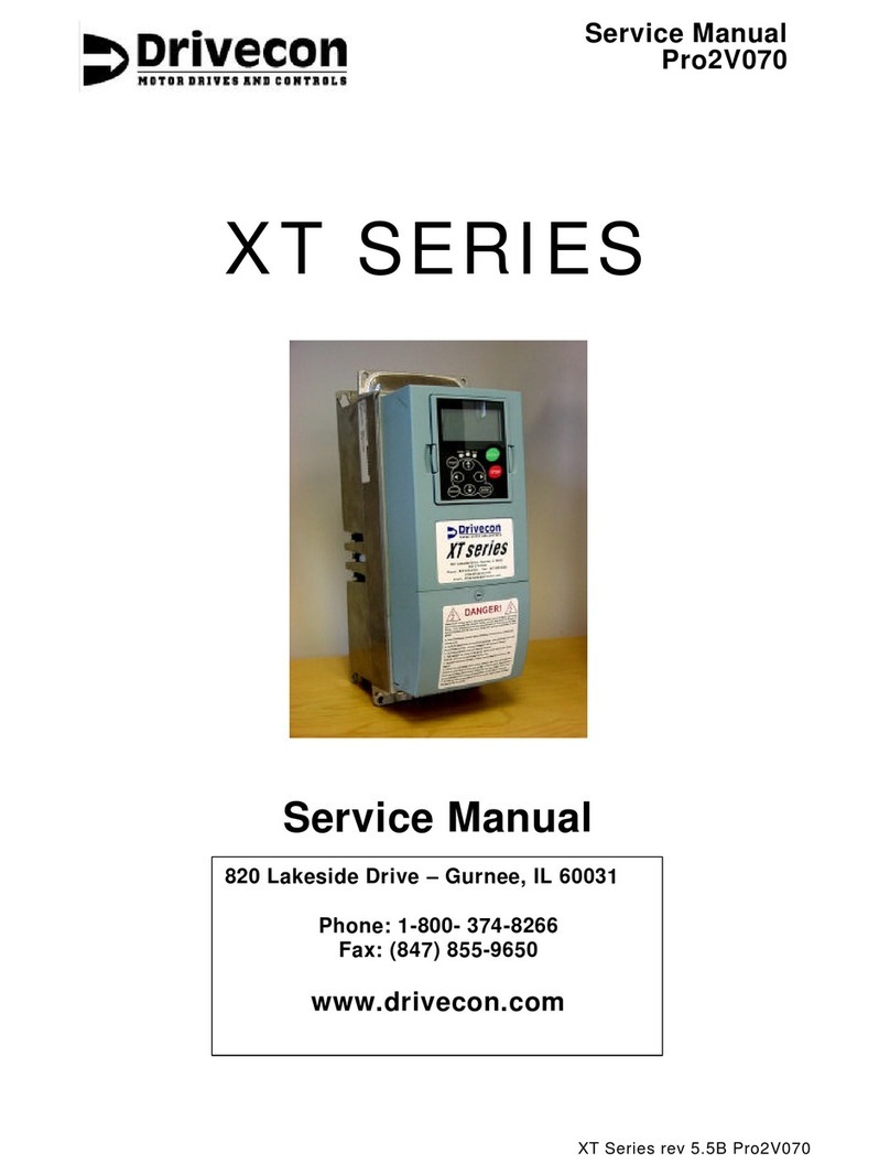
ACS Tech80 SB1391 User manual

SB1391
Single-Axis Universal Motion Control
Module
Hardware and Setup Guide
Document part no. TM-01391-000
Document revision no. 1.14

Document revision no. 1.14 (December 2001)
Document part no. TM-01391-000
COPYRIGHT
Copyright © 1999 - 2001 ACS-Tech80 Ltd.
Changes are periodically made to the information contained in this guide. The changes are published in
release notes and will be incorporated into future revisions of this guide.
No part of this guide may be reproduced in any form, without permission in writing from ACS-Tech80.
TRADEMARKS
ACS-Tech80 is a trademark of ACS-Tech80 Ltd. Corcom is trademark of Corcom Inc. LittleFuse is a
registered trademark of LittleFuse Inc. Phoenix Contact is a trademark of Phoenix Contact.
UL is a registered trademark of Underwriters Laboratories Inc. Visual Basic, Microsoft, and Windows are
registered trademarks of Microsoft Corp. The names of actual companies and products mentioned herein
may be the trademarks of their respective owners.
Website: http://www.acs-tech80.com/
E-mail: info@acs-tech80.com
support@acs-tech80.com
ACS-Tech80 Inc.
7351 Kirkwood Lane North, Suite 130
Maple Grove, MN 55369
USA
Tel: (1) (763) 493-4080 (800-545-2980 in USA)
Fax: (1) (763) 493-4089
ACS-Tech80 BV
Antonie van Leeuwenhoekstraat 18
3261 LT Oud-Beijerland
THE NETHERLANDS
Tel: (31) (186) 623518
Fax: (31) (186) 624462
ACS-Tech80 Ltd.
Ramat Gabriel Industrial Park
POB 5668
Migdal Ha'Emek, 10500
ISRAEL
Tel: (972) (4) 6546440
Fax: (972) (4) 6546443
NOTICE
Information deemed to be correct at time of publishing. ACS-Tech80 reserves the right to change
specifications without notice. ACS-Tech80 is not responsible for incidental, consequential, or special
damages of any kind in connection with this document.
Dangerous voltages are present in this equipment!
Contact with live parts could cause serious injury or death!
Refer connection, installation, maintenance, adjustment, servicing and
operation to qualified personnel.

RECENT CHANGES TO THIS GUIDE I
SB1391 Hardware and Setup Guide - Document revision no. 1.14
RECENT CHANGES TO THIS GUIDE
Ver. Date Section Change ECR
1-11 Sept./00 4.5.1 Description of CAN indicator LED states improved.
1-11 Sept./00 4.4.5 and
7.5.1.1
Warning added: Controller does not provide hardware
facilities for hardware Emergency Stop or Safety Interlock.
1-11 Sept./00 4.4.5 and
7.5.1.1
Warning added: E-STOP input is only for indicating that an
emergency situation exists. It cannot be used as the Emergency
Stop for the entire system.
1-11 Sept./00 4.4.3,
4.4.4,
and 7.3
Warning added: Encoder support does not include facilities for
over-speed protection.
1-12 Oct./00 4.3.3.1 Added replacement instructions for regeneration resistor fuse.
1-12 Oct./00 4.4.6 Corrected TABLE 4-22, connection pins for the HSSI/PEG
connector (J5).
296
1-13 Oct./00 7.5.4 Updated description of ACSPL analog output parameters.
1-13 Dec./00 4.3.1.1 Warning added for drive supply: If using secondary circuit to
supply the SB1391, supply must be suitably European
Approved.
1-13 Dec./00 4.3.1.1.3 Warning added for control supply: If using secondary circuit
or DC direct to supply the SB1391, supply must be suitably
European Approved.
1-13 Dec./00 4.4.5 Warning added for I/O supply: If using secondary circuit or
DC direct to supply the SB1391, supply must be suitably
European Approved.
1-13 Dec./00 4.3.2 Warning added for motor connection: Wiring and output must
be in accordance with the relevant safety requirements of the
EN 60204-1 standard (latest version).
1-13 Dec./00 4 Warning added for mounting (installation): The SB1391 must
be enclosed or incorporated into an end-product in accordance
with the EN 60204-1 standard (latest version) for electrical
shock, environmental (IP), and earthing requirements.
1-13 Jan./01 4.3.3.1 Description of internal fuses and external regeneration resistor
fuse added.
1-13 Jan./01 4.3.1.2 Control supply must be minimum 1.5A.
1-13 Jan./01 4.3.1.1.3 Description of phase-loss detection for three-phase drive
connection added.
1-13 Jan./01 Cover Copyright, area code, and disclaimer updated.

II RECENT CHANGES TO THIS GUIDE
SB1391 Hardware and Setup Guide - Document revision no. 1.14
Ver. Date Section Change ECR
1-13 Jan./01 5.3.2 Screen shots updated & new debugger disable function added
1-13 Jan./01 All 16-bit, RS-232, Stand-Alone, and all ACS-Tech80 SB…..
1-13 Feb./01 4.4.6 Maximum PEG delay & Minimum Pulse width added
1-13 Feb./01 3 Section 3 information updated to match Data Sheet
1-13 Feb./01 2 General Safety and EMC Guidelines section added
1-13 Feb./01 8 Other Topics section changed to Vector control and motors,
EMC section moved to Chapter 2.
1-13 Feb./01 5.2.6 Warning that motors are activated and ACScope output is
mirrored at the analog output added
1-13 Feb./01 5.2.10 Feedback sensor counting direction corrective measures added
1.14 Aug/01 4-24 Encoder 2 pins 2-7 are “Master Encoder...” Ltd33
1.14 Nov/01 2.1 UL compliance for section 508c. Ltd48
1.14 Nov/01 Cover
&9
Update cover page, trademark/contact info, and warranty
pages. New template added.

CONTENTS III
SB1391 Hardware and Setup Guide - Document revision no. 1.14
CONTENTS
FIGURES VII
TABLES XI
PREFACE XIII
1. INTRODUCTION 1-1
1.1. ABOUT ACS-TECH80 MOTION CONTROL MODULES 1-1
2. SAFETY AND EMC GUIDELINES 2-1
2.1. UL COMPLIANCE SECTION 508C2-1
2.2. GENERAL SAFETY GUIDELINES 2-3
2.3. GENERAL WIRING AND ELECTROMAGNETIC COMPATIBILITY (EMC) GUIDELINES 2-4
3. FEATURES & SPECIFICATIONS 3-1
3.1. MAIN FEATURES 3-1
3.2. PRODUCT SPECIFICATIONS 3-4
4. MOUNTING AND WIRING 4-1
4.1. MOUNTING 4-1

IV CONTENTS
SB1391 Hardware and Setup Guide - Document revision no. 1.14
4.2. WIRING DIAGRAM 4-3
4.3. POWER CONNECTORS 4-5
4.4. CONTROL CONNECTORS 4-14
4.5. INDICATORS, SWITCHES, DISPLAY, AND TEST POINTS 4-32
5. WORKING WITH THE CONTROL UNIT 5-1
5.1. GETTING STARTED 5-3
5.2. ADJUSTING THE UNIT 5-5
5.3. ACSPL PROGRAMMING WITH ACS DEBUGGER 5-45
5.4. DIRECT MODE 5-49
5.5. PROGRAM MODE 5-55
5.6. SAVING AND LOADING CONTROL UNIT MEMORY 5-65
6. TUNING THE CONTROL LOOPS 6-1
6.1. ABOUT D AND K ARRAYS 6-2
6.2. CONTROL LOOP BLOCK DIAGRAMS 6-4
6.3. CURRENT LOOP 6-11
6.4. COMMUTATION 6-14
6.5. VELOCITY LOOP 6-15
6.6. POSITION LOOP 6-18
6.7. SLIP CONSTANT OPTIMIZATION 6-21
6.8. POLISHING 6-22
6.9. DUAL LOOP CONTROL 6-24
7. HARDWARE INTERFACE PARAMETERS 7-1
7.1. SERIAL COMMUNICATIONS 7-2
7.2. CAN COMMUNICATIONS 7-5
7.3. ENCODER 1 AND ENCODER 2 7-9
7.4. HALL SENSORS 7-9
7.5. INPUT/OUTPUT PORTS AND MOTION MONITORING 7-9

FIGURES VII
SB1391 Hardware and Setup Guide - Document revision no. 1.14
FIGURES
FIGURE 2-1 Cable Spacing......................................................................................................... 2-4
FIGURE 2-2 Shielded Cable........................................................................................................ 2-4
FIGURE 2-3 Improved Shielding ................................................................................................ 2-5
FIGURE 2-4 Case shielding (top of control module) .................................................................. 2-5
FIGURE 4-1 SB1391 mounting dimensions................................................................................ 4-2
FIGURE 4-2 Wiring diagram....................................................................................................... 4-4
FIGURE 4-3 Wire stripping dimension for terminal block connections ..................................... 4-5
FIGURE 4-4 Power supplies and suggested use of line filter...................................................... 4-6
FIGURE 4-5 Electrical schematic of 12A, and 16A line filter for single-phase.......................... 4-8
FIGURE 4-6 Electrical schematic of 25A line filter for single-phase ......................................... 4-8
FIGURE 4-7 Electrical schematic of 6A line filter for three-phase............................................. 4-8
FIGURE 4-8 Electrical schematic of 12A and 16A line filter for three-phase ............................ 4-9
FIGURE 4-9 Jumper JP2 (factory default: installed) on driver board ......................................... 4-9
FIGURE 4-10 Three-phase motor connection ........................................................................... 4-11
FIGURE 4-11 Single-phase (DC brush) motor connection ....................................................... 4-12
FIGURE 4-12 Regeneration resistor - external and internal...................................................... 4-13
FIGURE 4-13 RS-232 connection ............................................................................................. 4-15
FIGURE 4-14 RS-422/485 connection ...................................................................................... 4-16
FIGURE 4-15 CAN bus ............................................................................................................. 4-17
FIGURE 4-16 Encoder interface................................................................................................ 4-19
FIGURE 4-17 Hall sensors connection...................................................................................... 4-20

VIII FIGURES
SB1391 Hardware and Setup Guide - Document revision no. 1.14
FIGURE 4-18 Internal 5Vdc supply connection for encoder and Hall ......................................4-21
FIGURE 4-19 External 5Vdc supply connection for encoder and Hall.....................................4-21
FIGURE 4-20 Resolver connection .......................................................................................... 4-23
FIGURE 4-21 Switch connection for temperature protection....................................................4-23
FIGURE 4-22 Jumpers for selecting I/O supply source and for selecting input type ................4-25
FIGURE 4-23 Jumper 12 for digital input-type selection..........................................................4-28
FIGURE 4-24 Input port interface .............................................................................................4-29
FIGURE 4-25 Output port interface........................................................................................... 4-30
FIGURE 4-26 Joystick connection ...........................................................................................4-30
FIGURE 4-27 PEG outputs and corresponding digital outputs ................................................. 4-32
FIGURE 4-28 The 7-segment display........................................................................................4-33
FIGURE 4-29 DIP switches (off)...............................................................................................4-34
FIGURE 4-30 Location of current test points............................................................................ 4-34
FIGURE 5-1 Working with the controller ................................................................................... 5-2
FIGURE 5-2 Adjustment procedure ............................................................................................ 5-6
FIGURE 5-3 Adjuster status bar ..................................................................................................5-8
FIGURE 5-4 "Communication error" message............................................................................ 5-9
FIGURE 5-5 Communications settings........................................................................................ 5-9
FIGURE 5-6 Choose version dialog box ................................................................................... 5-10
FIGURE 5-7 Add amplifier command.......................................................................................5-11
FIGURE 5-8 "Create a new amplifier database" message ......................................................... 5-12
FIGURE 5-9 Add new amplifier item dialog box...................................................................... 5-12
FIGURE 5-10 Opening the amplifier list................................................................................... 5-13
FIGURE 5-11 Amplifier specification (varies by type).............................................................5-14
FIGURE 5-12 Add motor command ..........................................................................................5-16
FIGURE 5-13 "Create a new motor database" message ............................................................5-16
FIGURE 5-14 Add new motor item dialog box......................................................................... 5-17
FIGURE 5-15 New motor record dialog box.............................................................................5-17
FIGURE 5-16 Motor type list ....................................................................................................5-18
FIGURE 5-17 Motor specification (varies by type)...................................................................5-18
FIGURE 5-18 Starting adjustment session ................................................................................5-21
FIGURE 5-19 Control unit warning before adjustment session ................................................5-22
FIGURE 5-20 Adjustment steps ................................................................................................ 5-22
FIGURE 5-21 Amplifier parameters step ..................................................................................5-23
FIGURE 5-22 Selecting the amplifier type................................................................................5-24

FIGURES IX
SB1391 Hardware and Setup Guide - Document revision no. 1.14
FIGURE 5-23 Amplifier parameters.......................................................................................... 5-24
FIGURE 5-24 Selecting the motor type..................................................................................... 5-25
FIGURE 5-25 Motor/feedback parameters................................................................................ 5-26
FIGURE 5-26 Protection parameters ......................................................................................... 5-27
FIGURE 5-27 Feedback verification step.................................................................................. 5-29
FIGURE 5-28 Current loop adjustment step.............................................................................. 5-30
FIGURE 5-29 Initial current loop profile .................................................................................. 5-31
FIGURE 5-30 Final current loop profile.................................................................................... 5-32
FIGURE 5-31 Commutation adjustment step ............................................................................. 5-33
FIGURE 5-32 Commutation preferences dialog box................................................................. 5-34
FIGURE 5-33 Prompt to write parameters to nonvolatile memory ........................................... 5-35
FIGURE 5-34 Adjustment in progress....................................................................................... 5-36
FIGURE 5-35 Successful completion of commutation.............................................................. 5-36
FIGURE 5-36 Velocity loop adjustment step ............................................................................ 5-37
FIGURE 5-37 Motion parameters (for velocity loop) ............................................................... 5-38
FIGURE 5-38 Typical velocity loop step response ................................................................... 5-38
FIGURE 5-39 Position loop adjustment step............................................................................. 5-39
FIGURE 5-40 Motion parameters (for position loop) .............................................................. 5-40
FIGURE 5-41 Typical velocity profile ...................................................................................... 5-41
FIGURE 5-42 Typical position error profile.............................................................................. 5-41
FIGURE 5-43 Review parameters step...................................................................................... 5-43
FIGURE 5-44 Editing parameters.............................................................................................. 5-44
FIGURE 5-45 "Save to controller nonvolatile memory" query................................................. 5-44
FIGURE 5-46 "Application saved to PC hard disk" confirmation ............................................ 5-45
FIGURE 5-47 Debugger status bar - successful communication with control unit................... 5-47
FIGURE 5-48 Opening the Debugger terminal ......................................................................... 5-48
FIGURE 5-49 Debugger terminal.............................................................................................. 5-48
FIGURE 5-50 Direct mode prompt............................................................................................ 5-49
FIGURE 5-51 Point to point move ............................................................................................ 5-50
FIGURE 5-52 Debugger main window ..................................................................................... 5-55
FIGURE 5-53 File window and Open dialog box...................................................................... 5-56
FIGURE 5-54 File window........................................................................................................5-57
FIGURE 5-55 Program for point to point move ........................................................................ 5-59
FIGURE 5-56 Program window shows the program in control unit RAM ............................... 5-60
FIGURE 5-57 Trace mode program execution.......................................................................... 5-61

X FIGURES
SB1391 Hardware and Setup Guide - Document revision no. 1.14
FIGURE 5-58 Opening the Trace window.................................................................................5-62
FIGURE 5-59 Trace window .....................................................................................................5-62
FIGURE 5-60 Program execution and trace messages ..............................................................5-63
FIGURE 5-61 Saving and loading control unit memory contents .............................................5-65
FIGURE 5-62 ACS Saver ..........................................................................................................5-66
FIGURE 5-63 ACS Loader ........................................................................................................5-67
FIGURE 6-1 Control algorithm ...................................................................................................6-6
FIGURE 6-2 Plant (motor + load) model.....................................................................................6-7
FIGURE 6-3 Commutation and power amplifier stage................................................................6-8
FIGURE 6-4 Current loop and filter ............................................................................................6-9
FIGURE 6-5 Velocity loop and filter.........................................................................................6-10
FIGURE 6-6 Current filter Bode diagram..................................................................................6-11
FIGURE 6-7 Current loop response after first Gain (D4) adjustment (step 4). .........................6-12
FIGURE 6-8 Current loop response after second Gain (D4) adjustment................................... 6-13
FIGURE 6-9 Current loop response after Integrator gain (D3) adjustment...............................6-13
FIGURE 6-10 Velocity proportional-integral filter Bode diagram............................................6-17
FIGURE 6-11 Velocity loop step response................................................................................ 6-18
FIGURE 6-12 Motion parameters dialog box............................................................................ 6-19
FIGURE 6-13 Position loop velocity response ..........................................................................6-20
FIGURE 6-14 Position loop error response ............................................................................... 6-21
FIGURE 6-15 Position error for various SK values...................................................................6-22
FIGURE 6-16 Position error profile when AF=0.......................................................................6-23
FIGURE 6-17 Position error profile when AF=500...................................................................6-23
FIGURE 6-18 DC brushless (AC servo/AC synchronous) motor - velocity vs. torque............. 6-24
FIGURE 6-19 Dual loop block diagram ....................................................................................6-26
FIGURE 7-1 Multiple drop connections for RS-232 ...................................................................7-3
FIGURE 7-2 Multiple drop connections for RS-422/485 ............................................................. 7-4
FIGURE 8-1 Vector control.........................................................................................................8-2
FIGURE 8-2 Current and magnetic field vectors.........................................................................8-3
FIGURE 8-3 Model of separately excited DC motor...................................................................8-3
FIGURE 8-4 Model of induction motor in synchronously rotating reference frame...................8-4

TABLES XI
SB1391 Hardware and Setup Guide - Document revision no. 1.14
TABLES
TABLE 2-1 Topics covered in this chapter ................................................................................. 2-1
TABLE 2-2 UL Compliance Label for SB1391 .......................................................................... 2-2
TABLE 2-3 External, user replaceable fuse for Regen Termination Resistor.............................. 2-2
TABLE 4-1 Topics covered in this chapter ................................................................................. 4-1
TABLE 4-2 Minimum recommended clearances ........................................................................ 4-3
TABLE 4-3 Power connectors.....................................................................................................4-5
TABLE 4-4 Single-phase drive supply current level ................................................................... 4-7
TABLE 4-5 Three-phase drive supply current level.................................................................... 4-7
TABLE 4-6 Drive supply connection pins................................................................................... 4-7
TABLE 4-7 Corcom line filters for single-phase power supply .................................................. 4-7
TABLE 4-8 Corcom line filters for three-phase power supply.................................................... 4-8
TABLE 4-9 Control supply connection pins ............................................................................. 4-10
TABLE 4-10 Motor connection pins ......................................................................................... 4-11
TABLE 4-11 Regen Connector.................................................................................................. 4-12
TABLE 4-12 Fuse replacement procedure ................................................................................ 4-14
TABLE 4-13 Control connectors............................................................................................... 4-14
TABLE 4-14 Serial connector pins............................................................................................ 4-15
TABLE 4-15 CAN connector pins............................................................................................. 4-16
TABLE 4-16 CAN connection troubleshooting......................................................................... 4-17
TABLE 4-17 Encoder 1 (+ Hall) connection pins ..................................................................... 4-18
TABLE 4-18 Resolver connection pins ..................................................................................... 4-22

XII TABLES
SB1391 Hardware and Setup Guide - Document revision no. 1.14
TABLE 4-19 Encoder 2 connection pins ...................................................................................4-24
TABLE 4-20 Digital input/output supply selection ...................................................................4-25
TABLE 4-21 Input/output connection pins................................................................................4-26
TABLE 4-22 HSSI + PEG connection pins ...............................................................................4-31
TABLE 4-23 Indicator LEDs.....................................................................................................4-33
TABLE 4-24 DIP switches ........................................................................................................4-34
TABLE 4-25 Current test points ................................................................................................4-35
TABLE 5-1 Topics covered in this chapter..................................................................................5-1
TABLE 5-2 Resources for more information about topics covered in this chapter.....................5-3
TABLE 5-3 ACS Tools................................................................................................................5-4
TABLE 5-4 Adjustment steps...................................................................................................... 5-5
TABLE 5-5 Amplifier record fields...........................................................................................5-14
TABLE 5-6 Motor record fields.................................................................................................5-19
TABLE 5-7 Detailed guidelines for calculating protective parameters .....................................5-28
TABLE 5-8 Two ways to read and set an ACSPL parameter....................................................5-46
TABLE 6-1 Topics covered in this chapter..................................................................................6-1
TABLE 6-2 D and K arrays .........................................................................................................6-2
TABLE 6-3 Removing and restoring Z and K array protection................................................... 6-3
TABLE 6-4 Displaying and setting values of D array elements..................................................6-4
TABLE 6-5 Displaying and setting values of K array elements..................................................6-4
TABLE 7-1 Topics covered in this chapter..................................................................................7-1
TABLE 7-2 Changing the baud rate.............................................................................................7-2
TABLE 7-3 CAN rotary switch positions and associated modes ................................................ 7-6
TABLE 7-4 Predefined motion state functions for digital outputs ............................................7-11
TABLE 7-5 Outputs commands.................................................................................................7-11
TABLE 7-6 MN (Monitor)parameter.........................................................................................7-12
TABLE 7-7 DC (Data Collection) parameter bit assignment ....................................................7-12
TABLE 7-8 Scale factor as a function of MF ............................................................................7-13

PREFACE XIII
SB1391 Hardware and Setup Guide - Document revision no. 1.14
PREFACE
The SB1391 Hardware and Setup Guide describes how to mount, connect, tune, and operate the
SB1391 motion control module. Regarding operation, only an introduction to the ACS-Tech80,
programming language, ACSPL, is provided. For a detailed description of ACSPL, refer to the
ACSPL Software Guide.
The information in this guide is organized sequentially according to the steps involved in
installing and setting up the control module. An index is included.
Conventions
Visual cues are used in this guide in an attempt to make it easier to absorb the information.
Note
A note box is used for information of special interest or importance.
Caution
A caution box is used when an action must be done with care. Otherwise minor
equipment damage or loss of data could occur.
Warning
A warning box is used when an action must be done with great care.
Otherwise personal injury or significant equipment damage can occur.
ACSPL terms appearing in the text are presented in bold style.
ACSPL program fragments are presented in bold Courier New typeface.

3-6 FEATURES & SPECIFICATIONS
SB1391 Hardware and Setup Guide - Document revision no. 1.14
Guide Outline
Chapter 1 INTRODUCTION. Introduction to the control module.
Chapter 2 SAFETY AND EMC GUIDELINES. Basic precautions and UL requirements.
Chapter 3 FEATURES & SPECIFICATIONS. Primary features of the control module and
specification.
Chapter 4 MOUNTING AND WIRING. Mounting information and electrical interface.
Chapter 5 WORKING WITH THE CONTROL UNIT. Setting up, tuning, and programming the
control module.
Chapter 6 TUNING THE CONTROL LOOPS. Detailed description of the control loops, how to
fine tune them, and how to implement dual loop control.
Chapter 7 HARDWARE INTERFACE PARAMETERS. Motion monitoring and other
programming guidelines for the communication, feedback, and I/O.
Chapter 8 VECTOR CONTROL AND MOTORS. Specialized topics for vector control for DC
brushless (AC servo/AC synchronous) and AC induction motors, and multiprogramming.
Note
For information developed after this guide was published, please refer to the
ACS-Tech80 web site (http://www.acs-tech80.com/) or contact ACS-Tech80.
Related Documentation
Programming the control module is covered in the Software Guide.

INTRODUCTION 1-1
SB1391 Hardware and Setup Guide - Document revision no. 1.14
1. INTRODUCTION
The SB1391 is a powerful and cost effective combination of an advanced programmable
controller, an all-digital drive, and a power supply (with a separate, backup input for the control
section).
The universal drive is software configurable for the any of the following types of rotary or linear
motor: DC Brushless (AC servo/AC synchronous) (with sinusoidal s/w commutation), AC
induction, and DC Brush. Three power levels are available: 5A (10A peak), 10A (20A), and 15A
(30A). The bus voltage range is 120Vdc up to 370Vdc (= AC input x 1.41).
The SB1391 supports encoder (+ Hall) or resolver (12-bit resolution) as primary feedback and
encoder as secondary feedback or master. In addition to dedicated safety inputs, it has eight
isolated inputs, eight isolated outputs, an analog input, and an analog output.
1.1. About ACS-Tech80 Motion Control Modules
ACS-Tech80 control modules are based on state of the art, proprietary technology that is used in
thousands of demanding systems, such as, semiconductor assembly and testing, electronic
assembly and inspection, digital printing, medical imaging, and packaging. Built-in capabilities
simplify programming common applications, such as advanced pick & place, master/slave, and
electronic gearing and cam.
The modules can be programmed to handle motion, time, and I/O events. They can operate stand-
alone, without a PLC or a PC. RS-232/422/485 serial communications is standard and CAN with
CANOPEN protocol is optional. Every module meets stringent safety and EMC standards and is
CE compliant.
Windows tools are provided for setting up and tuning the modules and for developing application
programs. C/C++ (Microsoft®and Borland) and Visual Basic®libraries are available for DOS,
Windows®3.11/95/98/2000/NT, and Linux. The libraries support multithreading in Windows
95/98/2000/NT.
ACS-Tech80 is certified compliant with the ISO 9001 quality management standard.

SAFETY AND EMC GUIDELINES 2-1
SB1391 Hardware and Setup Guide - Document revision no. 1.14
2. SAFETY AND EMC GUIDELINES
TABLE 2-1 Topics covered in this chapter
Topic Description
UL® Compliance Section 508c compliance requirements
General Electrical Safety Guidelines End-user installed protective devices and safety
precautions
General wiring and electromagnetic
compatibility (EMC) guidelines
Suggestions for proper wiring and shielding
2.1. UL Compliance Section 508c
UL Listed

2-2 SAFETY AND EMC GUIDELINES
SB1391 Hardware and Setup Guide - Document revision no. 1.14
TABLE 2-2 UL Compliance Label for SB1391
SB1391 -A -B -C
Model Input
Voltage
85-265Vac
(50/60 Hz, 1θ)
85–265Vac
(50/60 Hz, 1θ)
5-265Vac
(50/60 Hz, 1θ)
Model Input
Current
6.54A (rms) 14.5A (rms) 14.0A (rms)
Motor Type DC AC or DC
Brushless
DC AC or DC
Brushless
AC or DC
Brushless
Output Voltage 208Vdc 147.5Vac
(rms)
264.6Vdc 187.6Vac
(rms)
170.2Vac
(rms)
Output Current
per axis
5.0Adc 3.9A (rms) 10.0Adc 7.0A (rms) 9.5A (rms)
Output Current
per Module
5.0Adc 3.9A (rms) 10.0Adc 7.0A (rms) 9.5A (rms)
Control Input
Voltage
24Vdc 24Vdc 24Vdc
2.1.1. Overload, Over-current, and Over-speed Protection
Section 54.1: Degree of protection
Refer to TABLE 5-7 Detailed guidelines for calculating protective parameters.
Section 54.2: Thermal motor protectors
Refer to Section 4.4.3.5 Motor Temperature, for thermal switch and sensor specifications.
Section 54.3: Equipment employing ventilation
The following table outlines all external, user replaceable fuses.
TABLE 2-3 External, user replaceable fuse for Regen Termination Resistor
Fuse Size Type Manufacturer Part Number
Located in holder
on top of unit
1.5 Amp Fast-
Acting
600Vac/dc LittleFuse® KLKD001.5
Section 54.4: Supply source with specific over-current protective device
A recommended maximum input current protection device must be specified for each product.
This value should be equal to the specified input current rating of the module. Properly sized
circuit breakers shall be used for over-current and short-circuit protection.

SAFETY AND EMC GUIDELINES 2-3
SB1391 Hardware and Setup Guide - Document revision no. 1.14
Section 54.5: Not incorporating over-speed protection
Warning
Facilities for over-speed protection are not provided in the control unit.
Therefore, when facilities for over-speed protection are required for the end-
product, they will have to be provided separately by the end-user.
2.1.2. Branch Circuit Short Circuit Protection
Section 55.1: Short circuit rating and fuse information
Suitable for use on a circuit capable of delivering not more than 5,000 rms symmetrical amperes,
250 volts maximum.
2.1.3. Wiring Terminal Markings
Section 57: Wire Terminal Markings
Refer to FIGURE 4-2 Wiring diagram, for correct terminal connections. Chapter 4
MOUNTING AND WIRING, also contains all needed specifications regarding proper wire
type and size.
2.2. General Safety Guidelines
Under certain circumstances it is not enough to just power off the unit. For instance under
emergency situations the unit should be completely disconnected from any power supply. The E-
Stop and Left/Right Limits on ACS-Tech80 products are designed for use in conjunction with
customer installed devices to protect driver load. The end user is responsible for complying with
all Electrical Codes.
2.2.1. Emergency Stop
An emergency stop device shall be located at each operator control station and other operating
stations where an emergency stop may be required. The emergency stop device shall disconnect
any electrical equipment connected to the unit from the power supply. It will not be possible to
restore the circuit until the operator manually resets the emergency stop. In situations with
multiple emergency stop devices the circuit shall not be restored until all emergency stops devices
are manually reset.
2.2.2. Electrical Separation
Electrical separation is required between the control and power supply cables to prevent electrical
shock or damage to the equipment.
2.2.3. Over-Current Protection
Properly sized circuit breakers shall be used for over-current protection.

2-4 SAFETY AND EMC GUIDELINES
SB1391 Hardware and Setup Guide - Document revision no. 1.14
2.2.4. Power Supply and Motor Cable Ground
The power supply cable and the motor cable must have a ground wire that is connected to the
protective earth terminal located on the motor and power connectors. A connection must also be
made between the protective earth screw (located on the top of the unit) and the equipotential bar
inside electrical enclosure.
2.2.5. Thermal Detection
Suitable thermal detection shall be installed to interrupt the power circuit where abnormal
temperatures can cause a hazardous condition.
2.2.6. Over-Travel Protection
Over-travel limit protection shall be provided where over-travel is hazardous. The over-travel
limiting device shall be installed to interrupt the power circuit.
2.3. General Wiring and Electromagnetic Compatibility
(EMC) Guidelines
2.3.1. Routing Signal and Power Cables
Power cables (to the motor, mains outlet, etc.) and signal cables (to I/O, encoder, RS-232, etc.)
must be kept as far apart as possible. Keep at least an inch (∼2.5 cm) for each 3 feet (∼1 m) of
parallel run.
For example, if the motor and encoder cables run parallel for 6 feet (∼2 m), maintain a 2 inch (∼5
cm) separation between them.
Separation of 1 inch for every 3 feet
Motor Cable
Encoder / RS232 Cable
FIGURE 2-1 Cable Spacing
It is recommended to use cables that are completely shielded.
COVER SHIELD
FIGURE 2-2 Shielded Cable
This manual suits for next models
3
Table of contents
Popular Controllers manuals by other brands
Siemens
Siemens IP Controller N350E Technical product information
HIMA
HIMA HIMatrix F3 DIO 8/8 01 manual
Stealth Products
Stealth Products i-Drive 4.0 User's manual and maintenance guide
Resol
Resol DeltaSol MX Supplemental manual
Rain Bird
Rain Bird RC-4C instruction manual
Mitsubishi Electric
Mitsubishi Electric PAR-F27MEA-US installation manual

