manuals.online logo
Brands
  1. Home
  2. •
  3. Brands
  4. •
  5. Siemens
  6. •
  7. Controllers
  8. •
  9. Siemens IP Controller N350E User manual

Siemens IP Controller N350E User manual

GAMMA instabus
Technical Product Information
February 2013
IP Controller N350E 5WG1 350-1EB01
Siemens AG N350E, 4 Seiten Technical manual
Infrastructure & CitiesSector, Building Technologies
Control Products and Systems © Siemens AG 2013 Update: http://www.siemens.com/gamma
P.O.Box 10 0953,D-93009 Regensburg Subject to change without further notice 2.12.1.12/1
Product and Applications Description
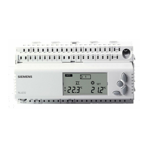
The IP Controller N350E is a DIN rail mounted device.
It provides these functions:
·Weekly scheduler
with up to 100 schedule entries for up to 80 channels,
with up to 8 periods for weekly schedules,
with astronomical schedule function
(+/- 2 hours from sun rise / sun set
·Annual schedule
with up to 50scheduleentries for up to 80channels
·30 Logic gates
·Event programs with a total of up to 200 event com-
mand actions
·Event program trigger via schedules, logic functions or
up to 30 threshold values
·Configuration of scheduler functions, event programs,
and logic functions via IP network
(protocol used: KNXnet/IP Device Configuration)
·Battery buffered real-time clock
·Display of date and time on LC-display
·Real-timeclock setting manually with three push but-
tons or automatically by a network (Internet) time ser-
vice
·Time zone selection for automatic time synchroniza-
tion
·Automatic Daylight SavingsTime change-over se-
lectable
·DHCP for automatic IP address assignment
·Communication via IP networkwith
- a visualization software
- ETS3 acting as a configuration interface
Via ETS up to 80objectscan be definedfor the device
with free data type assignment from thislist of data
types
·1 bit (EIS1)
·1 Byte, unsigned(EIS 14)
·1 Byte, signed (EIS 14)
·2 Byte, unsigned(EIS 10)
·2 Byte, signed (EIS 10)
·2 Byte,float (EIS 5)
·4 Byte, unsigned(EIS 11)
·4 Byte, signed (EIS 11)
·4 Byte,float (EIS 9)
All defined objects can be used freely by all software
modules.Hence, up to 80 objects can be selected from
forschedule functions, as input forlogic gates, asevent
triggers, or as output of event programs (scenes).
With the ETS (Engineering Tool Software) the application
program is selected, its parameters and addresses are
assigned appropriately, and downloaded to the IP Con-
troller N350E.
Application program
21 CO IP Controller 908701
·80 objects
·100 schedules
·50 annual schedules
·100 event programs (scenes)
·10 logic gates
·sends date and time
·IP communication for remote configuration and visual-
ization
Supported Software
Here is a list of software supporting the IP Controller
N 350E.
ComBridge Studio Evolution
IPAS GmbH
Hölscher Str. 27
47167 Duisburg
[http://www.ipas-products.com ]
ETS KNX Association
De Kleetlaan 5, Bus 11
B-1831 Brussels-Diegem
[http://www.knx.org ]
GAMMA instabus
Technical Product Information
February 2013
IP Controller N350E 5WG1 350-1EB01
Technical manual N350E, 4 Seiten Siemens AG
Infrastructure & CitiesSector, Building Technologies
Update: http://www.siemens.com/gamma © Siemens AG 2013 Control Products and Systems
Subject to change without further notice P.O.Box 10 0953,D-93009 Regensburg
2.12.1.12/2
Installation Instructions
·The device may be used for permanent interior instal-
lations in dry locations within distribution boards or
small casings with DIN rail EN 60715-TH35-7,5.
VWARNING
·The device must be mounted andcommissioned by an
authorised electrician.
·The device may be mounted to switch and socket
combination box mounts if VDE-certified devices are
used exclusively.
·The prevailing safety rules must beheeded.
·For planning andconstruction of electric installations,
the relevant guidelines, regulations andstandardsof
the respective country are to beconsidered.
Technical Specifications
Network communication
·Ethernet:
10BaseT (10 Mbit/s)
·Supported Internet Protocols:
ARP, ICMP, IGMP, UDP/IP, DHCP
·KNXnet/IP according to KNX System Specification:
Core, Device Management
Rated voltage
·Bus: DC 24V (DC 21...30V)
·Auxiliary power supply:
AC/DC 24V(AC/DC 12...30V)
Power supply
·Bus voltage:via KNX bus line
·Operating voltage:
from external SELV power supply AC/DC 24V nominal,
permissible input voltage range:
AC/DC 12 ... 30 V
·Recommended power supplies:
– DC 24V (beforechoke) from KNX powersupplies
N125/x2
Control elements
·1 learning button:
for switching between normal operating mode and
addressing mode
·3 push buttons(Move, Prg/Set, ESC):
on the front side to locally set date and time and to
display IP address, MAC address and firmware version
of the device
Display elements
·1 yellow LED: Ethernet Link Signal available (LK)
·1 yellow LED: Data transmission on Ethernet (LA)
·1 red LED: for monitoring bus voltage and displaying
mode, selected withthe learning button
·LC-Display, 2 rows with 12 characters each to display
date and time
Connections
·bus line: screwless bus connection block (red-black)
0,6...0,8 mm Ø single core
·Ethernet /IP network: RJ45 socket
·auxiliary power:
screwless extra low voltage terminal (yellow-white)
Æ0,6 ... 0,8 mm Øsingle core
Physical specifications
·housing: plastic
·DIN-rail mounted device,
width: 2 SUs (1SU = 18mm), height: 55 mm
·installation: rapid mounting on EN60715-TH35-7,5 rail
·weight: approx. 150g
Electrical safety
·degree of pollution (according to IEC 60664-1): 2
·protection (according to EN 60529): IP 20
·overvoltage class (according to IEC 60664-1): III
·bus: safety extra low voltage SELV DC 24 V
·the device complies with EN 50 090-2-2
Electromagnetic compatibility
complies with EN 50090-2-2
Environmental specifications
·climatic conditions: EN 50090-2-2
·ambient temperature operating: 0 ... + 45 °C
·storagetemperature:- 25 ... + 70°C
·relative humidity (non-condensing): 5 %to 93 %
Markings
EIB, KNX, CE
CE mark
complies with the EMC regulations (residential and func-
tional buildings), and low voltage regulations
GAMMA instabus
Technical Product Information
February 2013
IP Controller N350E 5WG1 350-1EB01
Siemens AG N350E, 4 Seiten Technical manual
Infrastructure & CitiesSector, Building Technologies
Control Products and Systems © Siemens AG 2013 Update: http://www.siemens.com/gamma
P.O.Box 10 0953,D-93009 Regensburg Subject to change without further notice 2.12.1.12/3
Location and Function of the Display and
Operator Elements
Figure 1: Location of thedisplay and operator elements
A1 AC/DC 24 V bus connector terminal (yellow-white)
A2 KNX bus connector terminal (black-red)
A3 Ethernet RJ45 socket
A4 KNX programming LED
A5 KNX learning button
A6 Display 2x12 characters
A7 MOVE push button
A8 Set/Prg push button
A9 ESC push button
A10 Ethernet Link LED
A11 Ethernet Activity LED
A12 Battery case
Setting time and date
In the display mode the LC-display shows time, day of
week, and date. Switch to the setup mode by depressing
the Set/Prg-push button (A8). Hour – Minute – Day –
Month – Year can be set in this order. Move from one to
the nextwith the Set/Prg-push button (A8). The selected
time/date value can be set by depressing the Move push
button (A7). Scroll through until the correct value is
displayed and then press the Set/Prg-push button (A8) to
move to the next time/date value.
After you enteredthe value for the year press the
Set/Prg-push button (A8). The device automatically
leaves the setup mode after approximatelyfive seconds.
The setupmode can be left by pressing the ESC push
button (A9).
Mounting and Wiring
General description
The N-system DIN-rail device can be installed in distribu-
tion boards, surface or flush mounted, or on any DIN rail
complying with EN 60715-TH35-7,5.
The connection to the bus line is established via the bus
connector terminal (red-black) on the top side.
The RJ45 socket on the device front side provides the
connection to the Ethernet-IP data network.
Mounting DIN-rail devices (Figure 2)
-Slide the device (Figure 2, B1) onto the DIN-rail (Figure
2, B2) and
-swivel back the device until the slide clicks into place
audibly.
-Connect the auxiliary power AC/DC 24V with the yel-
low-white bus connector terminal (A1).
-Connect the bus line with the black-red bus connector
terminal (A2).
-Plug an Ethernet patch cable with anRJ45 plug into
the RJ45 socket (A3) to connect the device with the
LAN / Intranet.
A connection is established to the network when the
yellow LED marked LK (A10) is continuously lit. When
the LED LA (A11) flashes data is sent to or from the de-
vice.
Dismounting DIN-rail devices
-Unplug the Ethernet patch cablefrom the RJ45 socket
(Figure 1, A3).
-Remove the yellow-white bus connector terminal (Fig-
ure 1, A1)from its socket.
-Remove the black-red bus connector terminal (Fig-
ure 1, A2)from its socket.
-press down the slide (Figure 2, C3) witha screw-driver
and
-swivel the device (Figure 2, C1) from the DIN-rail (Fig-
ure 2, C2).
B1 C1
C2
C3
B2
Figure 2: Mountingand dismounting a DIN-rail device
GAMMA instabus
Technical Product Information
February 2013
IP Controller N350E 5WG1 350-1EB01
Technical manual N350E, 4 Seiten Siemens AG
Infrastructure & CitiesSector, Building Technologies
Update: http://www.siemens.com/gamma © Siemens AG 2013 Control Products and Systems
Subject to change without further notice P.O.Box 10 0953,D-93009 Regensburg
2.12.1.12/4
Slipping off bus connection blocks (Figure 3)
-The bus connection block (D2) is situated on the top of
the device (D1).
-The bus connection block (D2) consists of two com-
ponents (D2.1 and D2.2) with four terminal contacts
each.Takecare notto damage the two test sockets
(D2.3) by accidentally connectingthem to the bus ca-
ble or with the screw-driver (e.g. when attempting to
unplug the bus connection block).
-Carefully put the screw-driver to the wire-inserting slit
of the bus connection block's grey component and
pull the bus connectionblock (D2)from the device
(D1).
Slipping on bus connection blocks (Figure 3)
-Slip the bus connection block onto the guide slot and
-press the bus connection block (D2) down to the stop.
Connecting bus cables (Figure 3)
-The bus connection block (D2) can be used with single
core conductors Ø 0,6 ... 0,8 mm.
-Remove approx. 5 mm of insulation from the conduc-
tor (D2.4) and plug it into the bus connection block
(D2) (red = +, black = -).
Disconnecting bus cables (Figure 3)
-Unplug the bus connection block (E1) and remove the
bus cable conductor (E1.4) while simultaneously wig-
gling it.
D2 D
D2 D2.
4
5 mm
D2
D2.4
D2.1 D2.2
D2
D2.3
Figure 3: Connecting anddisconnecting bus wires
Slipping off / on auxiliary power connection block
-Follow the instructions for the bus connection block
when slipping off/on the auxiliary power connection
block.
Battery change
-Lift the battery casecover (A12) with ascrew driver.
-Remove the batterywith the battery holder.
-Separate the old battery carefully from the battery
holder to which it is glued.
-Insert the new battery in the battery holder and insert
bothinto the battery case. Ensure correct polarity (+
symbol) to achieve correct function of the real-time
clock.
-Close the battery case with the battery case cover
(A12).
-Battery type: Lithium CR 1/2 AA
Dimension Diagram
Dimensions in mm
b
90
44
55
45
b = 4 SU
1 Standard unit (SU) = 18 mm
General Notes
·The operating instructions must be handed over to the
client.
·A faulty device shall be returned with a Return Good
Note for Service provided by the appropriate Siemens
sales office.
·If you have further questions concerning the product
please contact our technicalsupport.
'+49 (911) 895-7222
7+49 (911) 895-7223
*support.automation@siemens.com
D1

This manual suits for next models

2

Other Siemens Controllers manuals

Siemens 27086-TAB Owner's manual

Siemens

Siemens 27086-TAB Owner's manual

Siemens SIMOTION C User manual

Siemens

Siemens SIMOTION C User manual

Siemens GDB 1 Series User manual

Siemens

Siemens GDB 1 Series User manual

Siemens SQL36E65 User manual

Siemens

Siemens SQL36E65 User manual

Siemens HydroRanger 200 HMI User manual

Siemens

Siemens HydroRanger 200 HMI User manual

Siemens SIRIUS 3RW40 User manual

Siemens

Siemens SIRIUS 3RW40 User manual

Siemens RWD62U User manual

Siemens

Siemens RWD62U User manual

Siemens Simatic S7-1500 User manual

Siemens

Siemens Simatic S7-1500 User manual

Siemens RDE-MZ6 User manual

Siemens

Siemens RDE-MZ6 User manual

Siemens N 526E02 Service manual

Siemens

Siemens N 526E02 Service manual

Siemens OpenAir GLB Series User manual

Siemens

Siemens OpenAir GLB Series User manual

Siemens LMV37.4 Series Operator's manual

Siemens

Siemens LMV37.4 Series Operator's manual

Siemens SINAMICS S120 User manual

Siemens

Siemens SINAMICS S120 User manual

Siemens 3VA9 Series User manual

Siemens

Siemens 3VA9 Series User manual

Siemens SQM50.484R8A Owner's manual

Siemens

Siemens SQM50.484R8A Owner's manual

Siemens AP 118 User manual

Siemens

Siemens AP 118 User manual

Siemens RVL482 User manual

Siemens

Siemens RVL482 User manual

Siemens RVL471 Operator's manual

Siemens

Siemens RVL471 Operator's manual

Siemens OpenAir GLB 1E Series User manual

Siemens

Siemens OpenAir GLB 1E Series User manual

Siemens LMV37.4 Series Operator's manual

Siemens

Siemens LMV37.4 Series Operator's manual

Siemens BT300 LonWorks Instructions for use

Siemens

Siemens BT300 LonWorks Instructions for use

Siemens SQU83 User manual

Siemens

Siemens SQU83 User manual

Siemens LME7 Series Operator's manual

Siemens

Siemens LME7 Series Operator's manual

Siemens 6MD85 User manual

Siemens

Siemens 6MD85 User manual

Popular Controllers manuals by other brands

THORLABS BSC202 user guide

THORLABS

THORLABS BSC202 user guide

Johnson Controls Facility Explorer FX40 Product bulletin

Johnson Controls

Johnson Controls Facility Explorer FX40 Product bulletin

ITS Telecom EKSELANS CAP1 user manual

ITS Telecom

ITS Telecom EKSELANS CAP1 user manual

resideo Braukmann Z11AS installation instructions

resideo

resideo Braukmann Z11AS installation instructions

Datakom DKG-119 user manual

Datakom

Datakom DKG-119 user manual

Rayrun T110 quick start guide

Rayrun

Rayrun T110 quick start guide

Carrier A Series installation manual

Carrier

Carrier A Series installation manual

Bosch CL200 user manual

Bosch

Bosch CL200 user manual

RCS OMEGA-3v9s manual

RCS

RCS OMEGA-3v9s manual

TECshow NAVIGATOR 2 user manual

TECshow

TECshow NAVIGATOR 2 user manual

Thunder TDR15008 manual

Thunder

Thunder TDR15008 manual

Mainstream Engineering QwikSwap V3 installation guide

Mainstream Engineering

Mainstream Engineering QwikSwap V3 installation guide

VALERE Power BC Series Operation manual

VALERE Power

VALERE Power BC Series Operation manual

Olimpia splendid B0152 instruction manual

Olimpia splendid

Olimpia splendid B0152 instruction manual

Delem DA-52 Reference manual

Delem

Delem DA-52 Reference manual

National Instruments ExpressCard-8360 installation guide

National Instruments

National Instruments ExpressCard-8360 installation guide

Syris SYKD2N-H5 Install instructions

Syris

Syris SYKD2N-H5 Install instructions

KELCO F40-240LC Installing and using

KELCO

KELCO F40-240LC Installing and using

manuals.online logo
manuals.online logoBrands
  • About & Mission
  • Contact us
  • Privacy Policy
  • Terms and Conditions

Copyright 2025 Manuals.Online. All Rights Reserved.