Vident iMax Series User manual

iMax Series Scan Tool
USER MANUAL
SHENZHEN VIDENT TECHNOLOGY CO., LTD
Copyright ©2017 Vident Tech.

General Notice
For your own safety and the safety of others, and to prevent damage to the equipment and vehicles,
read this manual thoroughly before operating your scan tool. The safety messages presented below
and throughout this user’s manual are reminders to the operator to exercise extreme care when using
this device. Always refer to and follow safety messages and test procedures provided by vehicle
manufacturer. Read, understand and follow all safety messages and instructions in this manual.
Safety Precautions and Warnings
To prevent personal injury or damage to vehicles and/or the scan tool, read this instruction manual first
and observe the following safety precautions at a minimum whenever working on a vehicle:
Always perform automotive testing in a safe environment. Wear safety eye protection that meets ANSI
standards. Keep clothing, hair, hands, tools, test equipment, etc. away from all moving or hot engine
parts.
Operate the vehicle in a well-ventilated work area: Exhaust gases are poisonous.
Put blocks in front of the drive wheels and never leave the vehicle unattended while running tests.
Use extreme caution when working around the ignition coil, distributor cap, ignition wires and spark
plugs. These components create hazardous voltages when the engine is running.
Put the transmission in PARK (for automatic transmission) or NEUTRAL (for manual transmission) and
make sure the parking brake is engaged.
Keep a fire extinguisher suitable for gasoline/chemical/ electrical fires nearby. Ignition is on or the
engine is running.
Keep the scan tool dry, clean, free from oil/water or grease. Use a mild detergent on a clean cloth to
clean the outside of the scan tool, when necessary.
Warranty and Service
Limited One Year Warranty
We warrants to its customers that this product will be free from all defects in materials and
workmanship for a period of one (1) year from the date of the original purchase, subject to the following
terms and conditions:
1) The sole responsibility of our company under the Warranty is limited to either the repair or, at the
option of our company, replacement of the scan tool at no charge with Proof of Purchase. The sales
receipt may be used for this purpose.
2) This warranty does not apply to damages caused by improper use, accident, flood, lightning, or if the
product was altered or repaired.
3) We shall not be liable for any incidental or consequential damages arising from the use, misuse, or
mounting of the scan tool. Some states do not allow limitations on how long an implied warranty lasts,
so the above limitations may not apply to you.

Table of Contents
1 GETTING STARTED..........................................................................................................................................1
1.1 Tool Descriptions........................................................................................................................................ 1
1.2 Accessory Included.................................................................................................................................... 2
1.3 Specifications.............................................................................................................................................. 2
1.4 Preparation &Connections........................................................................................................................ 2
1.4.1 Preparation.......................................................................................................................................... 2
1.4.2 Connecting to Vehicle........................................................................................................................2
1.5 System Setup.............................................................................................................................................. 2
1.5.1 Select Language.................................................................................................................................3
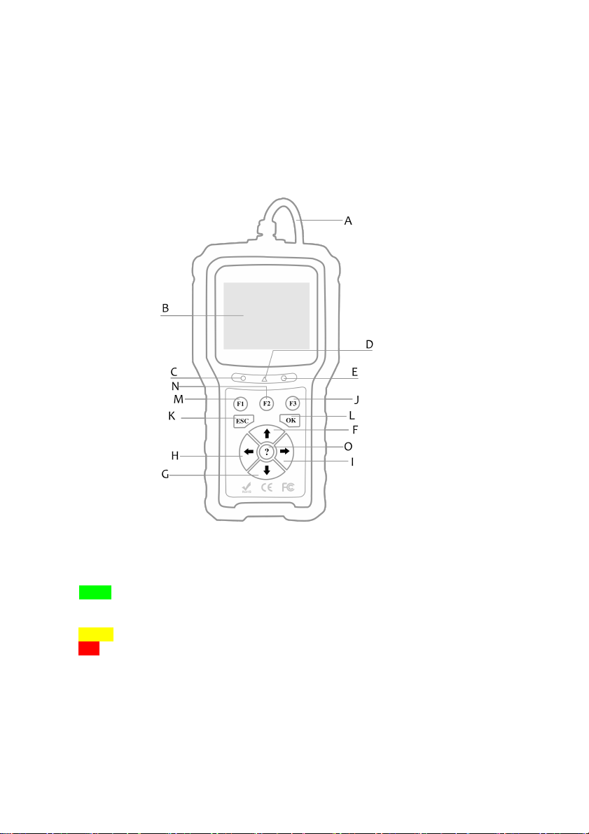
1.5.2 Unit of Measure.................................................................................................................................. 3
1.5.3 Beeper set........................................................................................................................................... 4
1.5.4 Key Test...............................................................................................................................................4
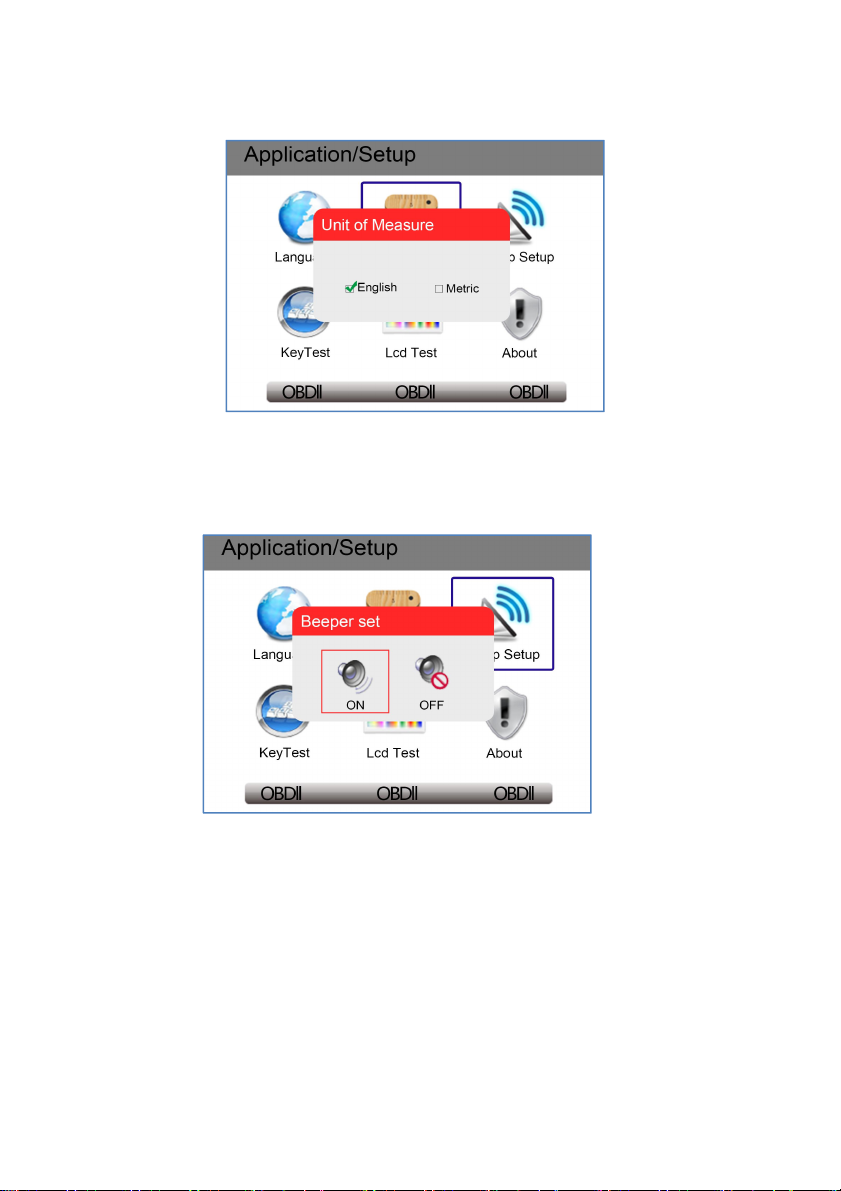
1.5.5 LCD Test..............................................................................................................................................4
1.5.6 About.................................................................................................................................................... 5
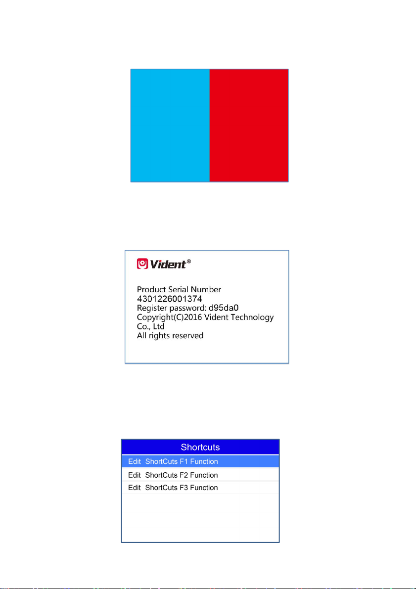
1.5.7 Configure Shortcut Keys................................................................................................................... 5
2 DIAGNOSTIC OPERATIONS...........................................................................................................................6
2.1 Vehicle Identification.................................................................................................................................. 6
2.1.1 Automatic VIN Acquisition.................................................................................................................6
2.1.2 Manual VIN Entry............................................................................................................................... 7
2.1.3 Manual Vehicle Selection..................................................................................................................8
2.1.4 Save a Tested Vehicle Info...............................................................................................................8
2.2 System Selection......................................................................................................................................10
2.2.1 Auto Scan.......................................................................................................................................... 10
2.2.2 Control Unit....................................................................................................................................... 11
2.3 Diagnostic Function..................................................................................................................................12
2.3.1 Read Codes...................................................................................................................................... 12
2.3.2 Erase Codes..................................................................................................................................... 13
2.3.3 Freeze Frame Data..........................................................................................................................13
2.3.4 ECU Information...............................................................................................................................13
2.3.5 Live Data........................................................................................................................................... 14
2.3.5.1 Complete Data List....................................................................................................................... 14
2.3.5.2 Custom Data List.......................................................................................................................... 15
3 COMMON SPECIAL SERVICES/FUNCTIONS.........................................................................................16
3.1 Oil Light Service/Reset............................................................................................................16
3.2 ABS Bleeding..........................................................................................................................16
3.3 Battery Matching.....................................................................................................................16
3.4 Electronic Parking Brake (EPB) Service.................................................................................16
3.5 Diesel Particulate Filter (DPF) Regeneration..........................................................................17
3.6 TPS(Throttle Body Alignment) ...............................................................................................17
3.7 Steering Angle Sensor (SAS) Calibration................................................................................17

3.8 TPMS Adaptation....................................................................................................................17
3.9 Immobilizer..............................................................................................................................17
3.10 Injector Coding......................................................................................................................17
3.11 Gear Learning.......................................................................................................................17
3.12 Suspension Match................................................................................................................17
3.13 Sunroof Initialization..............................................................................................................18
3.14 Gearbox Match.....................................................................................................................18
3.15 .Ajuste Fuel...........................................................................................................................18
3.16 Odometer Calibration............................................................................................................18
3.17 AFS (Adaptive Front Lighting System) .................................................................................18
3.18 PFP (Prime an Electric Fuel Pump)......................................................................................18
3.19 Turbo Match........................................ .................................................................................18
3.20 Door Window Calibration......................................................................................................18
3.21 Seat Match............................................................................................................................18
3.22 Dashborad Language Change..............................................................................................19
3.23 Clutch Adaptation................................ .................................................................................19
4 OBDII/EOBD DIAGNOSTICS........................................................................................................................ 19
4.1 Read Codes......................................................................................................................................... 19
4.2 Erase Codes.........................................................................................................................................19
4.3 Live Data...............................................................................................................................................20
4.3.1 View Data.......................................................................................................................................... 20
4.3.1.1 Complete Data Set....................................................................................................................... 20
4.3.1.2 Custom Data List.......................................................................................................................... 20
4.3.2 Record Data......................................................................................................................................20
4.3.3 Playback Data...................................................................................................................................21
4.4 View Freeze Frame.............................................................................................................................21
4.5 Read I/M Readiness Status Data..................................................................................................... 21
4.6 O2 Monitor Test................................................................................................................................... 24
4.7 On-Board Monitor Test....................................................................................................................... 24
4.8 Component Test.................................................................................................................................. 25
4.9 Request Vehicle Information............................................................................................................. 25
4.10 Modules Present............................................................................................................................... 25
4.11 DTC Lookup....................................................................................................................................... 25
4.12 System Status....................................................................................................................................25
5 PLAYBACK DATA...........................................................................................................................................26
6. SOFTWARE UPDATE AND PRINTING......................................................................................................27
6.1 Updating your tool.................................................................................................................................... 27
6.2 Printing Data..............................................................................................................................................27

1
1 Getting Started
iMax series is professional level diagnostic handheld tool, offering fundamental and basic diagnosis
of full systems for certain car manufacturer. Featured with all supported system diagnosis including
engine, transmission, ABS, Airbag, instrument, steering wheel, etc., and more than 10 commonly
required services, iMax series tool is a poweful must-have for each car owner.
1.1 Tool Descriptions
This section illustrates external features, ports and connectors of the scan tool.
AOBDII Cable-provides communication for vehicle DLC.
BLCD Display - shows menus, test results and operation tips.
CGreen LED Display- indicates electronic control module (ECM) is working normally (all
monitors on the vehicles are active and performing their diagnostic testing), and no DTCs are
found.
DYellow LED Display- shows the tool finds a possible problem.
ERed LED Display -indicates there are some problems in electronic control module (ECM)
tested. In this case, the MIL lamp on the instrument panel is on.
FUP Key - quick access to the Read Codes function before going to diagnostic menu and moves
selection up. When looking up DTC, it is used to change value of selected character.
GDOWN Key - Quick access to the Clear Codes function before going to diagnostic menu and
moves selection down. When looking up DTC, it is used to change value of selected character.
HLEFT SCROLL Key-goes to previous character when looking up DTCs. Scrolls back and forth
through codes found and through different screens of data. Also it is used to make selection of
PIDs when viewing custom PID list, and to view PID graphs.

2
IRIGHT SCROLL Key-goes to next character when looking up DTCs. Scrolls back and forth
through codes found and through different screens of data. Also it is used to cancel all
selections of PIDs when viewing custom PID list.
J,M, N Shortcut Key -configure user’s usual and favorite choices.Whenever there is choices at
bottom of diagnostic menu, they can also be used as confirmation button.
KESC Key - cancels an action and returns to previous screen or level.
LOK Key - confirms an action or movement and moves to next level.
O? Key - accesses to the Help function
1.2 Accessory Included
1) Scan tool
2) Diagnostic Cable
3) USB cable - connect to computer to update software
4) User’s Manual - instruction on tool operations.
5) Blow molding case - stores the scan tool and its accessories
1.3 Specifications
Display: Backlit, 2.8” TFT color display
Working Temperature: 0 to 60 ℃(32 to 140℉)
Storage Temperature: -20 to 70℃(-4 to 158℉)
Power Supply: 8-18V vehicle power, 12V AC/DC power
Tool Dimensions: 190*100*35 mm (L*W*H)
1.4 Preparation &Connections
1.4.1 Preparation
--Turn the vehicle ignition to ON position.
--Vehicle battery voltage should be 9~14 volts
--Throttle should be on a closed position.
1.4.2 Connecting to Vehicle
1. Locate the data link connector (DLC). The DLC is generally a standard 16 -pin connector
located 12 inches from the center of the steering wheel, under or around the driver’s side.
2. Plug the diagnostic cable into the vehicle DLC socket.
3. The scan tool automatically boots up.
1.5 System Setup
The System Setup functions allow you to adjust default settings and view information about the
scan tool. Options are :
●Language
●Unit
●Beep Set
●Key Test
●LCD Test
●About
●Shortcuts

3
1.5.1 Select Language
English is the default language.
1. Select Language from Setup menu and press the OK key.
2. Press the LEFT/RIGHT arrow key select a language and press the OK key to confirm.
1.5.2 Unit of Measure
To change the unit setup:
1. Select Units from Setup menu and press the OK key.
2. Press the LEFT/RIGHT arrow key select an item and press the OK key to save and return.

4
1.5.3 Beeper set
The default setting is Beep on.
1. Select Beep Set from Setup menu and press the OK key.
2. Press the LEFT/RIGHT arrow key to set the beep on or off and press the OK key to save.
1.5.4 Key Test
This function checks if the keys are working properly.
1. Select Key Test from Setup menu and press the OK key.
2. Press any key to start test. The virtue key corresponding with the key you pressed will be
highlighted on the screen if it works correctly. Otherwise, the key is not functioning properly.
3. Click the F2 function key twice to exit.
1.5.5 LCD Test
LCD test checks if the LCD is working properly.
1. Select LCD Test from Setup menu and press the OK key to start test. Check if there are any
missing spots in the LCD screen.

5
2. When completed, press the ECS key to exit.
1.5.6 About
Selecting Setup>About option opens a screen that show information about your scan tool, such
as serial number and register password which may be required for product registration.
1.5.7 Configure Shortcut Keys
Selecting Shortcuts option lets you to change the functionality of the shortcut buttons.
To assign a function to a shortcut button:
1. Select Shortcuts from Setup menu and press the OK key. A screen with available shortcut
keys displays.
2. Press the UP/DOWN arrow key select an shortcut key and press the OK key.

6
3. Scroll with the UP/DOWN arrow keys to highlight an application and press the OK key to
assign the application to the shortcut key.
2 Diagnostic Operations
This section illustrates how to use the scanner to read and clear diagnostic trouble codes, and
view “live” data readings and ECU information on controllers installed on the vehicles and also
save “recordings” of the data readings.
Following applications are preloaded into the scanner:
●OBDII/EOBD – OBDII/EOBD diagnosis for all 10 generic OBD modes.
●I/M Readiness – quick test and display the result of I/M.
●Scan – Marked with certain car make providing diagnosis of full systerm supported of this car
make.
●Service –commonly required maintenance.
NOTE:
Depending on car make, this service may vary.
●Setup – Basic tool setting.
●Playback – To access saved diagnostic data.
2.1 Vehicle Identification
The vehicle identification information presented is provided by the ECM of the vehicle being
tested. Therefore, certain attributes of the test vehicle must be entered into the scan tool to
ensure the data displays correctly. The vehicle identification sequence is menu driven, you simply
follow the screen prompts and make a series of choices. Each selection you make advances you
to the next screen.
It typically identifies a vehicle by any of the following means, The options available vary by vehicle
manufacturer, not all the following options are available for all vehicles.
●Automatic VIN acquisition
●Manual VIN entry
●Manual vehicle selection
●Vehicle data recorder
2.1.1 Automatic VIN Acquisition
Automatic VIN Acquisition only available on some manufacturers. It allows to identifying a vehicle
by automatically requesting the vehicle identification number (VIN).
1. When a vehicle make has been selected, the following screen displays. Select VIN acquisition
from the menu, and press the OK key.

7
2. The scan tool starts to communicate with the vehicle and read the Vehicle Specification or VIN
Code automatically.
3. Answer YES if the Vehicle Specification or VIN code is correct and a menu of controller
selection displays. Answer NO if it is incorrect, and you are required to enter the correct VIN
number manually.
2.1.2 Manual VIN Entry
Manual VIN Entry identifies a vehicle by manually inputting a 17-digit VIN code.
1. Select manual VIN entry. A virtual keyboard opens for VIN entry.

8
2. Input a valid VIN code and use the function key Finish to confirm. The scan tool starts to
identify the vehicle.
2.1.3 Manual Vehicle Selection
Manual Vehicle Selection identifies a vehicle by making several selections according to certain
VIN characters, such as sub-brand, model year, and engine size.
1. On each screen that appears, select the correct option and then press the OK key. Follow the
on-screen prompts until the menu of controller selection displays.
2.1.4 Save a Tested Vehicle Info.
The scan tool is able to save a tested vehicle by creating a Vehicle Record. It provides quick
identification of previously tested vehicle(s).
1. Identify the vehicle by any of the means above, and run an automatic system test by selecting
Auto Scan.

9
2. When the test finished, press the function key Save on the screen, and a screen with a virtual
keyboard displays.
3. Enter a unique name for this vehicle and save it, and you will see this new vehicle in Vehicle
Data Recorder menu.
To identify a previously tested vehicle:
1. Select Vehicle record and press the OK key to start.

10
2. Select the vehicle under test and press the OK key.
2.2 System Selection
When you have completed the identification of vehicle, a menu for selecting systems to test
displays. Menu options typically are
●Auto Scan
●Control Unit
2.2.1 Auto Scan
Auto Scan performs an automatic system test to determine which control modules are installed on
the vehicle and obtain diagnostic trouble codes (DTCs) overview.
1. Select Auto Scan from the menu and press OK to start.
2. When auto scan finishes, a menu with a list of installed controllers together with their DTC
overview displays.
3. If there is diagnostic trouble code(s) detected in a control unit, press the function key
corresponding with Display DTC on the screen to view details of code information, and press
the function key Quick Erase to clear them.
4. Select the system you would like to test, and press the OK key. When the scan tool has
established connection with the vehicle, the Function Menu displays.

11
2.2.2 Control Unit
Control Unit screen displays all controllers available to this specific vehicle manufacturer.
1. Select Control Unit from the menu and press the OK key. A controller menu displays.
2. Select the system you would like to test. When the scan tool has established connection with
the vehicle, the Function Menu displays.

12
2.3 Diagnostic Function
After a system is selected and the scan tool establishes communication with the vehicle, the
Function Menu displays. Typically the menu options are
●Read Codes
●Erase Codes
●Freeze Frame
●ECU Information
●Live Data
2.3.1 Read Codes
Read Codes menu lets you read trouble codes found in the control unit. Typical menu options
include:
●Present/Permanent/Current Codes
●History Codes
Present/Permanent/Current codes stored in a control module are used to help identify the cause
of a trouble or troubles with a vehicle. These codes have occurred a specific number of times and
indicate a problem that requires repair.
History codes are also referred to as past codes that indicate intermittent DTCs that are not
currently active.
1. Select Read Codes from Function Menu and press the OK key. A code list including code
number and its description displays.
2. Use the up and down arrow keys to scroll through data to select lines, and left and right arrow
keys to scroll back and forth through different screens of data.

13
2.3.2 Erase Codes
Erase Codes menu lets you to clear all current and stored DTCs from a selected control module.
Also it erases all temporary ECU information, including freeze frame. Erase Codes does not fix
the problem that caused the fault! DTCs should only be erased after correcting the condition(s)
that caused them.
1. Select Erase Codes from Function Menu and press the OK key. Follow the on-screen
instructions to complete the procedure.
2.3.3 Freeze Frame Data
Freeze Frame Data menu displays freeze frame data, a snapshot of critical vehicle operating
conditions automatically recorded by the on-board computer at the time of the DTC set. It is a
good function to help determine what caused the fault.
2.3.4 ECU Information
ECU Information screen displays the identification data of the control module under test, such as
the control module identification string and the control module coding.
1. Select ECU Information from the menu and press the OK key.
2. A screen with detailed information of the selected control module displays.

14
2.3.5 Live Data
Live Data menu lets you view and record real time PID data from a selected vehicle electronic
control module.
Menu options typically include:
●Complete Data List
●Custom Data List
2.3.5.1 Complete Data List
Complete Data List menu lets you view all live PID data from a selected system.
1. Scroll with the up and down arrow keys to highlight a line, if the One Graphic on the bottom is
highlighted, it indicates graphing is available for the selected line. Press the function key One
Graphic to display the PID graph.
2. Press the function key Two Graphics to display two PID graphs in one screen.

15
3. Press the function key Merge Graph to display two PID plots in one coordinate for easy and
intuitive diagnosis.
4. To record the data to memory of the scan tool, use the function key SAVE, and press Stop
Saving to stop recording at any time.
5. Press Text to return to text viewing of PID data.
6. Select Pause to suspend collecting data from the scan tool and use the Start key to resume
collecting data.
7. Press the ECS key to return to the previous menu.
2.3.5.2 Custom Data List
Custom Data List menu lets you to minimize the number of PIDs on the data list and focus on any
suspicious or symptom-specific data parameters.
1. Select Custom List from the menu and press the OK key. The custom data stream selection
screen displays. Scroll with the up and down arrow keys to highlight a line, press the OK key
and then repeat the action to make more selections.

16
2. When finished selection, use the function key VIEW DATA to display selected items.
3 Services/Maintenance
This section gives brief instructions of the most commonly required service and maintenance
operations. Typical service operation screens are a series of menu driven executive commands.
Follow on-screen instructions to complete the operation.
(Following services are applied to iMax series depending on specific car makes.)
3.1 Oil Light Service/Reset
a)If the service lamp is on, you must provide service for the car. After service, you need to reset
the driving mileage or driving time so that the service lamp turns off and the system enables the
new service cycle. b)After changing engine oil or electric appliances that monitor oil life, you need
to reset the service lamp.
3.2 ABS bleeding
When the ABS contains air, the ABS bleeding function must be performed to bleed the brake
system to restore ABS brake sensitivity.
If the ABS computer, ABS pump, brake master cylinder, brake cylinder, brake line, or brake fluid
is replaced, the ABS bleeding function must be performed to bleed the ABS.
3.3 Battery matching
Use the car diagnostic device to reset the car battery monitoring unit to clear original fault
information about insufficient battery electric quantity, and match the battery again and monitor
battery based on current battery information.
Battery matching must be performed in the following cases: a) Main battery is replaced. Battery
matching must be performed to clear original electric quantity insufficiency information and
prevent the related control module from detecting false information. If the related control module
detects false information, it will invalidate some electric auxiliary functions, such as automatic
start&stop function, sunroof without one-key trigger function, power window without automatic
function. b) Battery monitoring sensor. Battery matching is performed to re-match the control
module and motoring sensor to detect battery electric quantity use information more accurately,
which can avoid the instrument panel displaying false information.
3.4 Electronic Parking Brake (EPB) Service
EPB Service menu allows you to perform the service and maintenance of brake systems,
including deactivation and activation of the brake control system, bleeding brake fluid, opening
Table of contents
Other Vident Diagnostic Equipment manuals