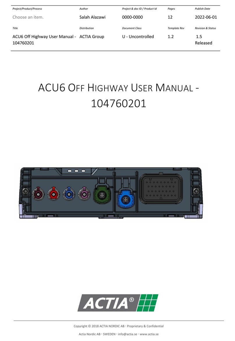
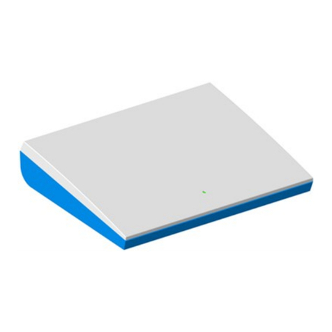
Actia VCM User manual

Owner
Nicklas Andersson
Date
2020
-
09
-
08
Classification
Document number
5610_4003
7
Revision
1.4
Title
VCM User Manual
Page
1
(
9
)
VCM
User Manual

Owner
Nicklas Andersson
Date
2020
-
09
-
08
Classification
Document number
5610_4003
7
Revision
1.4
Title
VCM User Manual
Page
2
(
9
)
Content
1 General ...................................................................................................................................................... 3
1.1 Revision history ................................................................................................................................. 3
1.2 Abbreviations .................................................................................................................................... 3
1.3 References ......................................................................................................................................... 3
2 Introduction ............................................................................................................................................... 4
3 Technical Description ................................................................................................................................ 5
3.1 Connectors ......................................................................................................................................... 5
3.1.1 DLC Ethernet connector ............................................................................................................ 5
3.1.2 USB/IHU Ethernet connector .................................................................................................... 5
3.1.3 Main connector .......................................................................................................................... 5
3.1.4 WLAN antenna .......................................................................................................................... 5
3.1.5 GNSS antenna............................................................................................................................ 5
3.2 Power supply ..................................................................................................................................... 5
3.2.1 Supported bands ........................................................................................................................ 6
3.3 WLAN ............................................................................................................................................... 6
3.3.1 Supported bands ........................................................................................................................ 6
4 Functional Description .............................................................................................................................. 7
4.1 Diagnostics ........................................................................................................................................ 7
4.1.1 DoIP connection ........................................................................................................................ 7
4.1.2 CAN connection ........................................................................................................................ 7
4.1.3 WLAN ....................................................................................................................................... 7
4.2 WLAN access point ........................................................................................................................... 7
4.3 Data gateway ..................................................................................................................................... 7
4.4 Positioning information ..................................................................................................................... 7
5 Installation and maintenance ..................................................................................................................... 8
5.1 Installation ......................................................................................................................................... 8
5.2 Maintenance ...................................................................................................................................... 8
6 Regulatory Certifications ........................................................................................................................... 9
6.1 USA (FCC) ........................................................................................................................................ 9
6.1.1 OEM Requirements ................................................................................................................... 9

Owner
Nicklas Andersson
Date
2020
-
09
-
08
Classification
Document number
5610_4003
7
Revision
1.4
Title
VCM User Manual
Page
3
(
9
)
1 General
1.1 Revision history
Revision
Author
Date
Description
1.0
Nicklas Andersson
201
7
-
08
-
31
First
version
1.1
Salah Alazawi
2017
-
10
-
09
Updated for FCC
1.2
Salah Alazawi
2019
-
09
-
12
Corrected FCC information
1.3
Nicklas Andersson
2020
-
07
-
03
Updated power values 5GHz WLAN
1.4 Nicklas Andersson 2020-09-08 Removed information for Canada
variant.
5.1 Added information about antenna
and cable length.
1.2 Abbreviations
Abbreviation
Meaning
DoIP
Diagnostics over IP
ECU
Electrical Control Unit
GNSS
Global Navigation Satellite System
OBD
On
-
Board Diagnostics
SRS
Supplemental Restraint System
WLAN
Wireless Local Area Network
1.3 References
Reference
Title
Doc. number
Revision

Owner
Nicklas Andersson
Date
2020
-
09
-
08
Classification
Document number
5610_4003
7
Revision
1.4
Title
VCM User Manual
Page
4
(
9
)
2 Introduction
The VCM is a connectivity ECU that is factory fitted in cars from Volvo Car Corporation (VCC).
It handles the diagnostic routing between the vehicle and the external test equipment for diagnostic
connections via CAN*, Ethernet/WLAN and Remotely via available Internet connections.
The VCM can also be used as a Wi-Fi hotspot for people inside the vehicle as well as a W-Fi client
to connect to available hotspots (for instance, a hotspot provided from a passenger’s laptop or cell
phone), and it provides raw GNSS position for use by other ECUs in the vehicle, such as the
Navigation system.
The VCM is capable of routing data to/from available Internet sources in the vehicle, for instance
the Wi-Fi station in the VCM, a Bluetooth handy connected to another ECU in the vehicle, or a
vehicle modem, also located in another ECU in the vehicle.
* Legislated OBD diagnostics (11-bit CAN) are not routed via the VCM.

Owner
Nicklas Andersson
Date
2020
-
09
-
08
Classification
Document number
5610_4003
7
Revision
1.4
Title
VCM User Manual
Page
5
(
9
)
3 Technical Description
3.1 Connectors
Connector No Function
1
DLC Ethernet
2
USB
/
IHU Ethernet
3
Main Connector
4
WLAN
antenna
5
GNSS antenna
3.1.1 DLC Ethernet connector
The DLC Ethernet connector is used for Ethernet communication with external diagnostics
equipment.
3.1.2 USB/IHU Ethernet connector
The IHU Ethernet connector is used for Ethernet communication with the head unit in the car.
3.1.3 Main connector
The main connector is used to connect power, FlexRay and CAN communication, external SIM
card holder, microphone and speaker, SOS, roadside assistance and exit buttons, and connection to
the SRS control unit.
3.1.4 WLAN antenna
The pastel orange Fakra connector is used to connect an external WLAN antenna.
3.1.5 GNSS antenna
The blue Fakra is the input for the GNSS antenna.
3.2 Power supply
Operating voltage range: 8-16 VDC. Nominal 13.8V.
Maximum current consumption 1.5A @ 8V.

Owner
Nicklas Andersson
Date
2020
-
09
-
08
Classification
Document number
5610_4003
7
Revision
1.4
Title
VCM User Manual
Page
6
(
9
)
3.2.1 Supported bands
Technology
Bands
GPS
L1
GLONASS
L1 FDMA
3.3 WLAN
The WLAN antenna is connected to the orange Fakra connector.
The product supports dual-band 802.11b/g/n at 2.4GHz and 802.11a/n at 5GHz. Supported
channels are listed below. When the product is installed in a vehicle the useable channels are
limited to what is allowed in the current country.
3.3.1 Supported bands
3.3.1.1 802.11b
Parameter
Channels
1
-
13
Data rates
1, 2, 5.5, 11 Mbps
Output power
+18 dBm
3.3.1.2 802.11g
Parameter
Channels
1
-
13
Data rates
6, 9, 12, 18, 24, 36, 48, 54 Mbps
Output power
+15 dBm
3.3.1.3 802.11n
Parameter
Channels 2.4GHz: 1-13
5GHz: 36
-
165
Data rates
MCS0
-
MCS7
Output power 2.4GHz: +15 dBm
5GHz: channesl 36-140: +13dBm,
channels 149
-
165 +11 dBm
3.3.1.4 802.11a
Parameter
Channels
36
-
165
Data rates
6, 9, 12, 18, 24, 36, 48, 54 Mbps
Output power 5GHz: channels 36-140: +13dBm,
channesl 149
-
165: +11 dBm

Owner
Nicklas Andersson
Date
2020
-
09
-
08
Classification
Document number
5610_4003
7
Revision
1.4
Title
VCM User Manual
Page
7
(
9
)
4 Functional Description
4.1 Diagnostics
4.1.1 DoIP connection
The DoIP interface in the vehicle is located in the OBD connector.
When a test equipment is connected on the OBD Ethernet port, the VCM presents itself on the
network using a “Vehicle Announcement Message”, as specified in ISO 13400-2. Based on the
content of this message, an external tester tool can connect to the VCM and create a diagnostic
session.
4.1.2 CAN connection
The diagnostics over CAN interface is also located in the OBD connector.
To communicate with the VCM and the ECUs behind the VCM in the vehicle topology, the
diagnostic requests shall be sent with 29-bit addressing.
The same CAN interface is used for legislated ODB diagnostics. For such purposes, 11-bit
addressing is used. Such CAN traffic does not affect the VCM.
4.1.3 WLAN
Diagnostics functionality is also available via WLAN. The unit ca be set in a mode where it acts
like a WLAN station and attaches to a hotspot in the workshop.
4.2 WLAN access point
VCM can act as a WLAN access point for passengers in the car.
User interface needs to be implemented in an external unit, e.g. in a head unit with display. The
WLAN access point functionality is controlled via IHU Ethernet interface.
4.3 Data gateway
VCM acts as a data gateway for the WLAN access point and other ECUs in the vehicle. It can e.g.
provide internet connectivity for the head unit.
The data gateway is controlled via the IHU Ethernet interface.
4.4 Positioning information
The product automatically outputs GNSS raw position data on the CAN bus.
The GNSS data is used by other ECUs in the vehicle, for instance the Navigation system.

Owner
Nicklas Andersson
Date
2020
-
09
-
08
Classification
Document number
5610_4003
7
Revision
1.4
Title
VCM User Manual
Page
8
(
9
)
5 Installation and maintenance
5.1 Installation
The VCM is factory fitted in Volvo vehicles. It is not possible to buy this product separately.
The product is certified to be used with an external roof mounted antenna.
Volvo part number 31346764
Minimum cable length is 2.5m.
5.2 Maintenance
The status of the VCM can be read via diagnostic connections using special workshop tools. In
addition, other ECUs monitor the communication from the VCM and in case of missing/invalid
communication, the Central Electronic Module in the vehicle is alerted, and will display a warning
to the driver.
Maintenance and replacement of the VCM can only be performed by Volvo certified workshops.

Owner
Nicklas Andersson
Date
2020
-
09
-
08
Classification
Document number
5610_4003
7
Revision
1.4
Title
VCM User Manual
Page
9
(
9
)
6 Regulatory Certifications
6.1 USA (FCC)
This device complies with Part 15 of the FCC rules. Operation is subject to the following two
conditions:
(1) This device may not cause harmful interference, and
(2) This device must accept any interference received, including interference that may cause
undesired operation.
6.1.1 OEM Requirements
Following text should be printed in the user manual for vehicles in US:
Type Approval USA
FCC ID: 2AGKKVCM
This device complies with Part 15 of the FCC rules. Operation is subject to the following two
conditions:
(1) This device may not cause harmful interference, and
(2) This device must accept any interference received, including interference that may cause
undesired operation.
WARNING: Changes or modifications not expressly approved by the party responsible for
compliance could void the user's authority to operate the equipment.
Table of contents
Other Actia Diagnostic Equipment manuals
