Actisense USG-1-B-485 User manual

USB to Serial Gateway
User Manual
USG-1-B-485
For use with RS485 Industrial Interfaces and
Maritime IEC 61162-2 connections
Issue 1.04
Create a safe serial port connection to an RS485 network or an IEC61162-2
compliant marine connection that may be on a different power circuit.
Provide a fully compliant RS485 port from a USB port
Receive low level differential signals that are too small to be received directly
by a PC serial port


USB to Serial Gateway - USG-1-B-485
Page 3© 2009 Active Research Limited
Contents
Important Notices 4
Notices 4
Foreword 4
Introduction 4
RS485 & IEC61162-2 4
USG-1 solutions 5
Solution #1 - Ground loops 5
Solution #2 - Different standards 5
Solution #3 - PC has no serial port 5
Features 5
Software updates 5
RS485 Interfacing 6
The basics 6
The RS485 signals 6
Opening the USG-1 6
USG-1 connections 7
Connecting Devices 8
RS485 Connections 8
Connecting to a 3-pin RS485 Listener or Talker (IEC 61162-2) 9
Connecting to a Personal Computer RS232 port 9
USB Driver Installation 10
Step by step guide 10
USB Conguration 12
Step by step guide 12
Troubleshooting guide 14
Diagnostic LED 14
Specications 15
Company Information 16

Page 4© 2009 Active Research Limited
Important Notices
Actisense and the Actisense logo are registered
trademarks of Active Research Limited. All rights are
reserved. The contents of this manual may not be
transferred or copied without the expressed written
permission of Active Research Limited. All other
trademarks are the property of their respective owners.
The Actisense USB to Serial Gateway (USG-1-485)
is intended for use in a marine environment, but only
below decks. If the unit is to be used in a more severe
environment, such use may be considered misuse under
the seller’s warranty.
The Actisense USG-1-485 has been certied to
comply with the European directive for Electro-Magnetic
Compatibility (EN60945), and is appropriately CE marked.
Operation of the unit should be in conjunction with
appropriate CE approved shielded connectors and cabling
used in accordance with the CE directive EN60945. Any
EMC related issues should be reported to Active Research
immediately to allow the company to rectify or resolve
EMC related problems in accordance with its obligations
under EN60945.
If the unit is connected such that compliance failure occurs
beyond the company’s control, the company shall not be
held responsible for compliance failure until suitable EMC
guidelines for connection are seen to have been taken.
Notices
When using this document, keep the following in mind:
The products described in this manual and the
specications thereof may be changed without prior notice.
To obtain up-to-date information and/or specications,
contact Active Research Limited or visit the Actisense
website (www.actisense.com).
Active Research Limited will not be liable for infringement
of copyright, industrial property right, or other rights of a
third party caused by the use of information or drawings
described in this manual.
All rights are reserved: The contents of this manual may
not be transferred or copied without the expressed written
permission of Active Research Limited.
Active Research Limited will not be held responsible for
any damage to the user that may result from accidents
or any other reasons during operation of the user’s unit
according to this document.
Foreword
Actisense recognises that instructions are often skipped,
so we have aimed to write this document in an informative,
yet direct manner that will aid the user. We have tried
to cover all the points a typical user may need to know.
Please read all sections before installing and using the
Actisense USB to Serial Gateway product.
Introduction
The Actisense USB to Serial Gateway (USG-1-485)
product developed out of the requirement to solve three
fundamental problems with interfacing the industry RS485
communications standard to a PC.
These are:
1. Ground loops. When the PC and the connected
system have different ground potentials (or are
totally different ground altogether), data can become
corrupted and permanent damage can occur.
2. Different standards. When you buy a standard USB
to serial converter, they normally provide PC standard
RS232 port, whereas RS485 uses a differential bi-
directional signalling system. This means that a
standard USB to serial converter is incompatible with
RS485 / IEC61162-2 that uses the RS485 electrical
driver type.
3. PC has no serial port. Most modern PCs do not
come with serial ports any more as these are being
replaced by the new standard of USB. Furthermore,
RS485 signals are not directly compatible with
standard PC serial ports.
Full information on the complete Actisense product range
can be found on the Actisense website.
RS485 & IEC61162-2
The port provided by the USG-1-B-485 will be referred
throughout the document as “RS485” although the
IEC61162-2 marine standard uses the same interface,
and the two terms are interchangeable.
The IEC61162-2 interface is not normally used in a
bidirectional mode, however, and is generally referred to
as a three-wire RS422 system. The differential signalling
method and the output driver levels are compatible
between the two systems.

USB to Serial Gateway - USG-1-B-485
Page 5© 2009 Active Research Limited
USG-1 solutions
Solution #1 - Ground loops
The rst problem encountered when using a standard
USB to serial converter (or a standard RS232 port) is that
the ground of the PC is then shared with the connected
system ground.
PCs are often powered from a mains inverter, generator
set or direct from mains supply when in dock, whereas the
marine electronics are normally connected to the current
marine battery set.
This means that when you connect the two systems
together, you are joining two different power systems.
This can result in no visible problems, but more often it
results in one of three consequences:
1. Data corruption - the data becomes garbled as the
electrical data signal now oats on a noisy ground
current owing between the two power systems.
2. The PC crashes intermittently as ground currents
ow across its sensitive electronic circuitry. This can
cause permanent damage.
3. In the case of large ground loop faults, some
components can melt / catch re / fuses blow or earth
leakage devices trip.
The USG-1-485 solves all these problems by providing
a safe, opto-isolated barrier between the two systems.
Because the signal travels across this barrier as light,
the signals do not share the same ground, and safety is
assured as no current can ow between the two power
systems. In addition, a built-in power isolator completes
the isolation.
Solution #2 - Different standards
PC serial or “COM” ports use the RS232 standard. This
uses a ground and a receive pin to get data from a
connected system. Data is sent as voltages referenced
to ground on a single transmit line. This type of drive is
known as “single-ended”.
In contrast, RS485 systems use a “differential” system,
where a “Positive” data line and a “Negative” data line
move in opposition to each other.
Many installations without isolated outputs have been
seen where the negative data line on a differential drive
system has been connected to the ground of the PC. If
you’re lucky, this may work, but if not, you will either simply
get no data, or at worst, damage your equipment.
The USG-1-485 solves this by using ingenious circuitry
unique to Actisense in its bi-directional transmitter
circuit. Please refer to the Interfacing section for more
information.
Solution #3 - PC has no serial port
Many laptop and desktop PCs do not come equipped
with RS232 type serial ports (which could be converted to
an RS485 type using a simple converter) any more. The
USG-1-485 solves this by creating a standard RS485 port
from any PC USB port.
This port appears on the PC system as a regular “COM”
port, and so can be used with all standard navigation and
display software.
Features
Standard USB connection - Equipped with a type “A”
USB connector to connect to a USB port or hub (USB v1.1
or v2.0 compliant).
Opto-isolated ISO-Drive transceiver technology
creates a transceiver, unique to Actisense, that is isolated
to 1500 volts - say goodbye to ground loop issues!
ISO-Drive allows a completely “oating” output to be
created, making a safe connection to a PC an easy
task. You can use the ISO-Drive output to safely transfer
data to an RS485 device, or to another PC. The output
automatically changes between differential and single
ended drive depending upon the type of instrument it is
connected to.
When not transmitting, the USG-1-485 automatically
switches to receive mode. The output becomes
a differential input fully compliant with the RS485
specication. This allows the USG-1-485 to work correctly
with long cable runs and in a noisy environment. Typical
operating voltage is 2.0v to 12.5v. The unit can withstand
-8/+12.5v continuously, and +/- 40v transients. The input
is also compatible with RS232 signal levels.
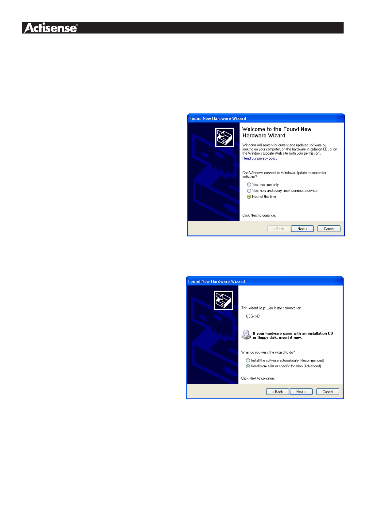
PC USB drivers supplied on disc - the drivers allow the
USG-1 to appear as a standard “COM” port on the PC.
Low current consumption - the USG-1-485 is powered
directly from the USB port on your PC, so no extra power
cables are required.
Tough Polycarbonate case - certied to IP54 (Splash
and dust proof) when used with both supplied cables.
Software updates
The USG-1 has no built-in rmware, but Actisense will
be providing updates to the PC USB drivers free on
our website, www.actisense.com when they become
available.

Page 6© 2009 Active Research Limited
RS485 Interfacing
The basics
RS485 interfaces are much like RS422 interfaces, but with
the ability for the connection to be a listener or a talker
depending upon port direction.
The USG-1 transceiver changes direction automatically.
When installed on a PC, the USB driver sets up a virtual
communications port ”VCP” on the host PC. When data is
sent to this port, the USG-1-485 transceiver automatically
becomes a driver and sends data to the RS485 network.
Once all data has been sent, the transceiver automatically
switches back to receive mode.
In addition, an optional link on the USG-1-485 board can
be set to “echo” mode, where data on the bus sent from
the USG-1-485 returns back to the PC. This link is factory
set to “no echo”.
Actisense produces a full range of products to solve many
marine and other interfacing requirements.
Please visit the Actisense website for full details on
these and other Actisense interfacing products (NMEA
Multiplexers, NMEA Buffers, and NMEA Autoswitches) as
well as Depth sounders.
The RS485 signals
RS485 uses a ”differential” signalling scheme, whereby two
wires are used to transmit the data. These connections will
be labelled as either “A” and “B“ or “+” and “-“ respectively,
depending on the instrument and manufacturer.
When connecting between different manufacturers, there
can be some confusion, but it is simple and easy to
remember: “A” connects to “+” and “B“ connects to “-“.
Opening the USG-1
The USG-1 comes supplied with a factory installed
connection cable with tinned solder wire ends. Using this
cable means that you will not need to open the USG-1-
485 case to make your connections.
If you need to use your own cable, Phoenix style
connectors are provided within the USG-1-485 to allow
you to connect it. A separate grommet is also provided for
this purpose - simply slide it over your own cable before
connecting it to the Phoenix style connectors.
To open the USG-1-485, remove the two screws in the
base of the USG-1, then slide off the top of the case. The
grommets need to be slid off the top of the case in order to
access the internal connections. You will be left with the
USG-1-485 circuitry attached to the base of the unit and
the two supplied cables attached to their connectors.
Note: When opening the USG-1-485 case, be aware
that the circuitry inside is not 100% protected against
static electricity. Please ensure that, when opening
the case, you use precautions against static damage
- by only touching the connector block and by holding
the unit by its base. In this way, the risks of static
damage will be minimised.

USB to Serial Gateway - USG-1-B-485
Page 7© 2009 Active Research Limited
USG-1 connections
Figure 1 – Inside the USG-1 case
Figure 1 shows an internal view of the USG-1 Printed
Circuit Board (PCB). The USG-1 has screw-terminal
“Phoenix” type connectors with a pre-installed cable.
This cable should be sufcient for most installations. The
colour codes used for this cable are:
Wire colour Function
Shield / Screen ISO-Drive Ground
Blue ISO-Drive RS485 B/-
White ISO-Drive RS485 A/+
Black ISO-Drive RS485 B/-
Red ISO-Drive RS485 A/+
This cable also has a screen connection. This is not
connected inside the USG-1: in most instances, simply
connect this to ground at the instrument end, and this will
provide correct screening of the signals on the USG-1-485
data cable.
1/2. An RS485 bidirectional connection.
Two sets of screw-terminal Phoenix-style connectors
(1 &2 in gure 1) are provided to connect the RS485
network. These connectors are provided for use
when the customer needs to use their own cable.
The bottom set of three screw-terminal Phoenix-style
connectors provide a second set of connections to
the RS485 network, along with a reference to the
oating ground of the USG-1-485 driver circuitry to
use where required.
Both sets of connections provide connections: ‘+/
A’, ‘-/B‘. This allows the USG-1-485 to interface to
various different devices that require any combination
of these outputs. Both sets are connected in parallel
on the board. This allows a network to be created,
by allowing a connection in from the RS485 network,
and the second set used to connect to further devices
on the network.
Note: The connection marked “GND” on the
connection block 3 is not USB or PC ground, it
is connected to the isolated ground of the ISO-
Drive circuit. In most installations, this GND should
be left disconnected. It is only for use in special
circumstances where an RS485 3-terminal type
connection is required, and is reserved only for
specialist installations. No damage will be caused
by connecting to this GND in error, but it may result
in missing or corrupted data if it is used incorrectly.
Always follow the connection diagrams shown in this
manual to ensure correct operation.
3. A micro-connector to connect to the supplied
USB type A terminated cable.
This connector should not normally be removed:
it is installed at the factory and is not customer
serviceable.
4. An indicator LED - USB
This LED ashes when data is sent from or received
from the USB side of the USG-1. It can be clearly
seen through the USG-1’s translucent lid when the
case is closed.
5. An indicator LED - RS485
This LED ashes when data is sent from or received
from the RS485 side of the USG-1. It can be clearly
seen through the USG-1’s translucent lid when the
case is closed.
6. An echo-mode header
Connecting the supplied link between pins 1 and 2
sets the “echo” mode, which returns all data sent by
the PC. Connecting pins 2 and 3, sets the “no echo”,
mode, which is the factory default.
5
3
1
2
4
1
2
6

Page 8© 2009 Active Research Limited
RS485 Connections
Figure 2 shows a typical installation with an RS485 network
connected into the lower connections of the connector
(connection 3 on Figure 1), and the network continuing on
via the second set of connections above.
The USG-1-485 maintains full isolation of the PC from
both ground and signal lines.
The ground (GND) connection may be connected to the
network as a reference ground. This is not the same as the
PC ground - it is the isolated ground used by the RS485
transceiver on the USG-1-485.
Connecting Devices
Figure 2 – RS485 connections
RS485
Net In
A/+
RS485
Net Out
B/-
A/+
B/
Ground
Notes:
1. It is recommended that all device interconnection
cables used should meet the two-conductor, shielded,
twisted pair conguration specication. The shield
connection of these wires should be connected at
the instrument end only to prevent ground loops.
2. Throughout these connection diagrams, the wire
colours represent those actually used on the supplied
Actisense USG-1-485 data cable. When using the
supplied cable, simply use the colours indicated to
connect to your network or instrument.
3. Refer to the Specicationssection for the full details
on input/output specications.

USB to Serial Gateway - USG-1-B-485
Page 9© 2009 Active Research Limited
Connecting to a Personal Computer RS232 port
It is possible to connect the USG-1-485 to a PC’s serial
communications (RS232) port, however, the resulting PC
connection would not be bidirectional - as communication
can only work one-way (either receive only, or transmit
only, but not both).
It is therefore, highly recommend to use an Actisense
USG-1-422 model instead, using the RS232 connections
detailed in that user manual. This method will allow full bi-
directional isolated connection to a PC RS232 port.
Connecting to a 3-pin RS485 Listener or Talker (IEC 61162-2)
Figure 3 – RS485 / IEC 61162-2 port connections
The USG-1 transceiver can be connected to an IEC61162-2
Listener, and / or Talker that requires a differential drive
plus ground as shown in gure 3, The USG-1 serial port
will default automatically to listen mode when no data is
being sent (from an ‘RS485 Talker’) to the virtual serial
port representing the USG-1-485 on the PC.
RS485 Listener
and / or Talker
A/+
GND
B/-

Page 10© 2009 Active Research Limited
USB Driver Installation
The Actisense USG-1 makes use of a virtual serial port
driver (know as the Virtual COM Port Driver) to interface
between the USB port on the PC and the Actisense
product. This driver allows software running on a PC
to communicate with the Actisense USG-1 as if it was
connected to a standard serial port on the PC, when in
fact all communication is done over the USB connection.
The required driver installation comes in two separate
packages. The rst driver is a called the ‘Serial Converter’
which converts the USB data packets to a serial data
stream. The second driver, called the ‘Actisense USB
Serial Port’, makes the USB connection appear as a COM
port in the Windows Device Manager.
The USG-1 with USB connection has been extensively
tested with both Windows XP and Windows 98 SE.
For the experienced Windows XP user who is used to
installing drivers, this section will be very familiar. To all
other Windows users, the required steps are detailed
below to help with installation.
The steps for Windows 98 SE are very similar to those of
Windows XP and so are not detailed here.
The Actisense CD also contains the USB drivers for
Windows 2000. These drivers have not been tested by
Actisense, but should operate in the same manner as the
Windows 98 SE and XP drivers.
The required Linux drivers are already included in the
Linux kernels from v2.4.20 and onwards. However,
Actisense has not been able to test the compatibility of
the USG-1 with USB and this driver.
For MAC OS 8, 9, and X please contact Actisense for
details (refer to the Company Information section).
Step by step guide
1. Make sure the Actisense USG-1 is connected to an
available USB port on the PC. The standard Windows
‘Found New Hardware Wizard’ window will then appear.
Select the ‘No, not this time’ option, to allow driver
installation from the Actisense CD which was supplied
with your Actisense product.
2. Insert the Actisense CD, choose the ‘Install from a
list or specic location’ option, and click ‘Next’.

USB to Serial Gateway - USG-1-B-485
Page 11© 2009 Active Research Limited
3. Make sure the ‘Include this location in the search’
option is ticked, and use the ‘Browse’ button to locate the
‘USB Drivers’ directory on the Actisense CD.
4. The ‘Actisense USB Serial Converter’ driver is not
Microsoft Windows certied, but it has been ‘tried and
tested’ for stable and reliable operation with the Actisense
USG-1. Click ‘Continue Anyway’ to carry on with the
installation.
5. The ‘USB Serial Converter’ driver is now installed,
click ‘Finish’ to complete the wizard, and wait for the
‘Found New Hardware Wizard’ to appear again.
This second wizard will guide you through the ‘USB Serial
Port’ driver installation.
6. Follow steps 1to 5above for the ‘USB Serial Port’
driver installation and click ‘Finish’ to complete.
‘Your new hardware is installed and ready to use’ will
appear in the bottom right corner of your screen when the
installation is complete. See the USB Driver Conguration
section for details on how to nd out which COM port
number has been allocated to your Actisense device
as well as how to change to a different COM port and
congure the Baud rate.

Page 12© 2009 Active Research Limited
USB Conguration
To communicate with the USG-1, the COM port number
that Windows has allocated to the USB port needs to be
determined. The following guide will walk the user through
this standard operation.
The Actisense USB to Serial Gateway, USG-1 is
completely USB port independent: it can be easily
unplugged from one USB port and connected to another
available USB port on the same PC without the COM Port
number changing.
To achieve this independent operation, plug the USG-1
into each required USB port that you require it to work
with in turn, install the USB drivers and manually change
the allocated COM port number to the same number for
each USB port. Once congured, the COM port number
will not change unless instructed to do so by the user.
This is very useful when the USG-1 is working in unison
with a software program that is set up to use a particular
COM port, as the user does not need to re select a
different COM port every time the PC re boots, or the
cable is swapped between two USB ports.
Step by step guide
1. Make sure the Actisense USG-1 is connected to an
available USB port on the PC. From the Windows ‘Control
Panel’, open the ‘System Properties’ window and click
on the ‘Hardware’ tab.
2. Click on ‘Device Manager’ and expand the ‘Ports
(COM & LPT)’ list by clicking on the ‘+’ sign next to it. You
will nd the ‘Actisense USG’ in the list, followed by the
allocated COM port number.

USB to Serial Gateway - USG-1-B-485
Page 13© 2009 Active Research Limited
3. Double click on the port icon for the ‘Actisense USG’
and the port properties window will appear. Click on the
‘Port Settings’ tab. Here you can set the default settings
for the USG-1 device. It is not necessary to change the
default settings here - as each software program will
dene these settings itself.
4. Click on the ‘Advanced’ button and choose a different
COM Port number if required (to make it compatible with
the software requiring the USG-1 RS485 data).
The other settings are already optimised for the Actisense
USG-1 and should be left in the default values. Click on
‘OK’ button to save the new settings.

Page 14© 2009 Active Research Limited
Troubleshooting guide
This guide will concentrate on all relevant troubleshooting issues above simple cable connection faults. Therefore,
the cables between the USG-1 hardware and any other devices should be checked as a matter of course, before
continuing with this guide.
Diagnostic LED
The USG-1 hardware has a bright LED that can be seen through the case to indicate when data is either received or
transmitted. It can be used to debug potential problems. If you have both a talker and a listener connected, then you
can analyse which is working by disconnecting one of them or by stopping the PC from sending data.
Mode / Error condition Required user response
LED does not ash when the
PC is sending data
Check that the PC program is sending data and that it has opened the comms port
assigned (by user) or allocated (by Windows Device Manager) to the USG-1
LED does not ash when the
Talker is sending data
Check that the ‘Talker’ device is correctly connected to the USG-1-485, that it is
powered on, and that it is sending data. In addition, the USB driver must be
correctly installed and the PC software must have the assigned comms port
open for the LED to ash
No data is being received
by the Listener, but LED is
ashing as PC is sending
Check that the ‘Listener’ device is correctly connected to the USG-1-485, that it is
powered on, and that it is set to receive data at the Baud rate of the PC comms port.
If there is a cable problem that has activated the short-circuit protection, the
protective poly-fuses will have activated to protect the USG-1-485 from damage. In
this case, remove the cable fault and wait 1 minute before reconnecting the USG-1
to the RS485 network.
If the error persists, the USG-1-485 unit should be returned to Actisense (refer to
the Company Information section). Please contact Actisense before returning
the unit in order to obtain a Returns Number.
Any returns sent without a Returns Number will incur a delay in being
processed. Any returns that are not found to be faulty will incur the minimum
servicing charge.
Table 1 – Diagnostic LED colours

USB to Serial Gateway - USG-1-B-485
Page 15© 2009 Active Research Limited
Specications
Parameter Conditions Min. Max. Unit
Supply
Supply voltage From USB port 4.75 5.25 V
Supply current drawn from USB port Supply voltage = 5v (no load) 40 46 mA
Supply voltage = 5v (output shorted) 75 80 mA
RS485 Transceiver Input / Output
Input voltage between +/- Logical ‘1’ 2.0 15.0 V
Logical ‘0’ -0.3 0.5 V
Input current - 1.0 mA
Differential input voltage Required level for data to be detected -0.2 0.2 V
Output voltage between +/- and ground
(under no load)
Logical ‘1’ 0.0 0.5 V
Logical ‘0’ 4.5 5.0 V
Output current at max load of 100 ohm At maximum load, differential drive
voltage reduces to 1.4v - 14 mA
Output short circuit current (note 1) Due to short circuit protection 50 55 mA
Galvanic isolation From USB ground 1500 V
Static discharge protection Yes
PC Communication settings
Baud rate Both input & output Baud rates are set
by the PC software settings 300 115200 bps
General
Ambient temperature -20 +70 °C
Table 2 – USG-1-485 specications
All specications are taken with reference to an ambient temperature (TA) of +25°C.
Note:
1. Short circuit may be applied indenitely. The RS485 transceiver input / output may be short-circuited directly to a
30 volt battery supply without damage. A maximum current of 50mA will ow due to “polyfuse” auto-resetting fuse
technology being used.

Page 16© 2009 Active Research Limited
Active Research Limited
5, Wessex Trade Centre
Ringwood Road
Poole
Dorset
UK
BH12 3PF
Telephone: 01202 746682 (International : +44 1202 746682)
Fax: 01202 746683 (International : +44 1202 746683)
Actisense on the Web: For advice, support and product details
E-mail: [email protected]
Website: www.actisense.com
“Actisense” is a registered trademark of Active Research Limited.
Company Information
Order codes:
USG-1-485 USG-1 for use with RS485 industrial interfaces
USG-1-422 USG-1 for use with NMEA 0183 and RS422 interfaces
Table of contents
Other Actisense Gateway manuals

Actisense
Actisense NGX-1-ISO User manual

Actisense
Actisense USG-1-B-422 User manual

Actisense
Actisense USG-2 User manual

Actisense
Actisense NMEA NGW-1 User manual

Actisense
Actisense USG-2 User manual

Actisense
Actisense NMEA NGW-1-ISO User manual

Actisense
Actisense NGT-1 User manual

Actisense
Actisense NMEA NGW-1 User manual

Actisense
Actisense W2K-1 User manual

Actisense
Actisense NMEA 2000 User manual
Popular Gateway manuals by other brands

Securakey
Securakey ENTRACOMP 28SA Plus User & installation manual

Multitech
Multitech MultiVOIP MVPGK1 Gatekeepers quick start guide

Thomas&Betts
Thomas&Betts Nexus RF user guide

LINK LABS
LINK LABS LL-BST-8 quick start guide

Black Box
Black Box AlertWerks AW3000 user manual

SmartRG
SmartRG SR360n quick start guide