manuals.online logo
Brands
  1. Home
  2. •
  3. Brands
  4. •
  5. 2N
  6. •
  7. Gateway
  8. •
  9. 2N SmartGate UMTS User manual

2N SmartGate UMTS User manual

Other 2N Gateway manuals

2N EasyGate IP User manual

2N

2N EasyGate IP User manual

2N SpeedRoute User manual

2N

2N SpeedRoute User manual

2N VoiceBlue Next User manual

2N

2N VoiceBlue Next User manual

2N EasyGate Pro User manual

2N

2N EasyGate Pro User manual

2N BRI Lite User manual

2N

2N BRI Lite User manual

2N EasyGate User manual

2N

2N EasyGate User manual

2N OfficeRoute User manual

2N

2N OfficeRoute User manual

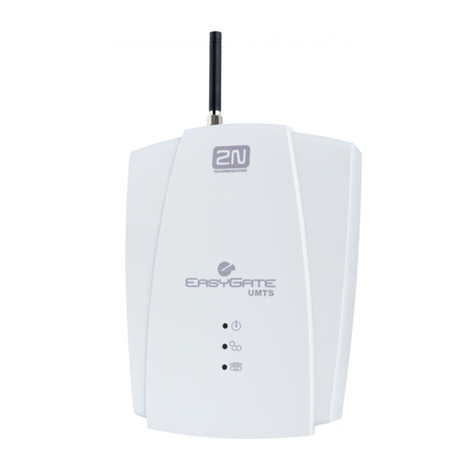
2N EASYGATE UMTS User manual

2N

2N EASYGATE UMTS User manual

2N VoiceBlue Next User manual

2N

2N VoiceBlue Next User manual

2N VoiceBlue MAX User manual

2N

2N VoiceBlue MAX User manual

2N SpeedRoute User manual

2N

2N SpeedRoute User manual

2N ISDN BRI GSM User manual

2N

2N ISDN BRI GSM User manual

2N EasyGate User manual

2N

2N EasyGate User manual

2N VoiceBlue Next User manual

2N

2N VoiceBlue Next User manual

2N EasyRoute Installation and user guide

2N

2N EasyRoute Installation and user guide

2N EasyGate Pro User manual

2N

2N EasyGate Pro User manual

2N SmartGate User manual

2N

2N SmartGate User manual

2N stargate User manual

2N

2N stargate User manual

2N VoiceBlue Next User manual

2N

2N VoiceBlue Next User manual

2N BRI Lite User manual

2N

2N BRI Lite User manual

2N EasyGate Pro User manual

2N

2N EasyGate Pro User manual

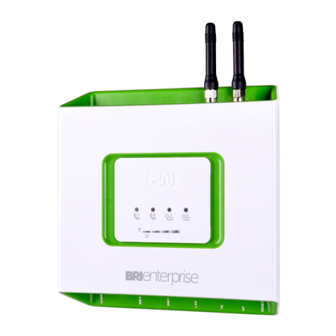
2N ISDN BRI GSM Enterprise User manual

2N

2N ISDN BRI GSM Enterprise User manual

2N BRI Lite User manual

2N

2N BRI Lite User manual

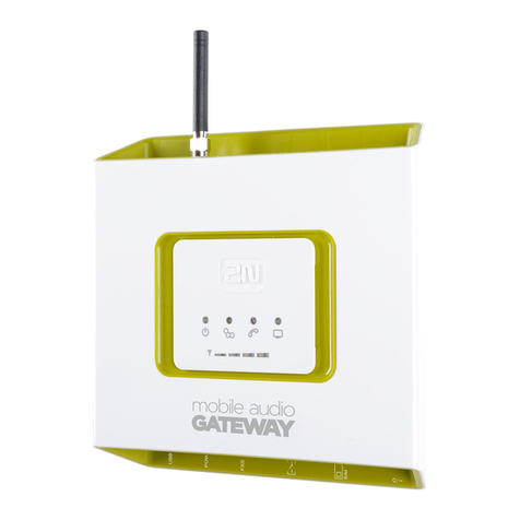
2N Mobile Audio Gateway Guide

2N

2N Mobile Audio Gateway Guide

Popular Gateway manuals by other brands

Telecom FM onestream gfx Programming guide

Telecom FM

Telecom FM onestream gfx Programming guide

UfiSpace LoRa GPE810U Quick setup guide

UfiSpace

UfiSpace LoRa GPE810U Quick setup guide

Merak MMk-736F Quick setup guide

Merak

Merak MMk-736F Quick setup guide

Robustel R3010 user guide

Robustel

Robustel R3010 user guide

turck BL20-PG-EN-V3 user manual

turck

turck BL20-PG-EN-V3 user manual

IBM Security Web Gateway Appliance quick start guide

IBM

IBM Security Web Gateway Appliance quick start guide

SSS Siedle Smart Gateway Commissioning instructions

SSS Siedle

SSS Siedle Smart Gateway Commissioning instructions

ADTRAN 424RG Installation

ADTRAN

ADTRAN 424RG Installation

Chorus Hyperfibre XGS-250WX-A user guide

Chorus

Chorus Hyperfibre XGS-250WX-A user guide

Dragino G308 user manual

Dragino

Dragino G308 user manual

Data Domain DD690g Installation and setup guide

Data Domain

Data Domain DD690g Installation and setup guide

Raritan Laptop Release notes

Raritan

Raritan Laptop Release notes

Haivision Torpedo quick start guide

Haivision

Haivision Torpedo quick start guide

ATCOM AG-268 user manual

ATCOM

ATCOM AG-268 user manual

LST M500RFE-AS Specification sheet

LST

LST M500RFE-AS Specification sheet

Vega VEGA BS-3 user manual

Vega

Vega VEGA BS-3 user manual

Kinnex Media Gateway quick start guide

Kinnex

Kinnex Media Gateway quick start guide

2N Telekomunikace 2N StarGate user manual

2N Telekomunikace

2N Telekomunikace 2N StarGate user manual

manuals.online logo
manuals.online logoBrands
  • About & Mission
  • Contact us
  • Privacy Policy
  • Terms and Conditions

Copyright 2025 Manuals.Online. All Rights Reserved.

Calls–DialThruGateway
By default, 2N®SmartGateUMTSbehaves
asadial-thrugateway:
•Callsareroutedto UMTS/GSMfrom
the FXS interface.
•IncomingUMTS/GSMcallsringatthe
FXS interface.
•WhentheFXOinterfaceisringing,
2N®SmartGateUMTSinterconnects
FXOandFXS,thusenablinganalogue
interfacesto communicatewitheach
other.
Formoreadvancedcallrouting,youhave
to programtheroutingtables.Some
distributorsofferproductswithpre-
programmed routing forplanned use:
•2N®SmartGateUMTScanroutecalls
fromtheFXS interfaceto UMTS/GSM
andFXOaccordingto thecalled
number,thuscuttingtheoutgoingcall
costssignificantly.Be sureto program
theFXS routingtableproperlyusing
yourPCandthePCManager
programming toolenclosed.
•ME–MobilityExtension isapplied
wheneveracall iscoming(ringing)to
theFXOinterface.WithME enabled,the
FXS andFXOlinesareinterconnected
andacall issetupto thedefined
UMTS/GSMnumber.Hence,aFXOcall
can beansweredontheFXS interface
and/orUMTS/GSMnetwork.
Calls–PBXInternal Line
Gateway
Byprogrammingasingleparameter
assignedto theFXOroutingtable,you
can switch2N®SmartGateUMTSintothe
PBX internalline mode:
•CallsfromtheFXOinterfacearerouted
to the UMTS/GSMnetwork.
•Toroute incoming UMTS/GSMcallsback
to theFXOinterface,youalsohaveto
setroutingtoFXOontherowforother
numbersintheGSMroutingtable.(To
make2N®SmartGateUMTSprocess
callsfromdifferentUMTS/GSMcallers,
completetheGSMroutingtablerowsas
necessary.)
ConfigurationviaUSB
•ToenableconfigurationviaaPC,
connect2N®SmartGate UMTSto the
PCusingaUSB cableandinstall the
2N®SmartGate PCManagertool.
•Thusyoucreateavirtualserialport
(USB serialport, FTDI)forthe
PCManagerconnectionto thegateway
(launchCDM20814_Setup.exeto install
the drivers).
•Selectthevirtualserialportnumberin
the PCManagersetup.
•Referto thefull UserManualversionfor
details.
ConnectiontoInternet, SMS
•2N®SmartGateUMTScan beusedasa
modemforPCconnectionto GPRS,
EDGE,UMTSandHSDPAnetworksand
thusprovideahighspeedInternet
connection.
•Install themodemdriversfromthe
Watcher_Generic_B2849.msifilebefore
connecting 2N®SmartGate to the PC.
•When2N®SmartGateUMTSis
connectedandswitchedon,theAirCard
Watcherprogramislaunched
automatically,whichhelpsyouaccess
the Internetorsend and receive SMS.
•Be sureto setAPNandotherprovider’s
settingsifnecessaryintheconnection
profilebeforeconnectingto the
Internet.
•Referto thefull UserManualversionfor
details.
IntheGSMnetwork,datatransfersaresuspendedduringvoicecallsand
donotcontinueuntil thevoicecall hasbeenfinished,whereasinthe
UMTS(3G)network,dataandvoicearetransferredsimultaneously.
ECDeclarationofConformity
2NTELEKOMUNIKACEa.s. herebydeclaresthat the2N®SmartGateUMTSproductisin compliancewiththe
basicrequirementsand otherrelevant provisionsof Directive1999/5/EC.RefertotheCD-ROMenclosed or
www.2n.cz forthefull wordingof theDeclarationof Conformity.
©2011,2NTELEKOMUNIKACEa.s.–Prague, LH1713,v.1.00
2N® SmartGateUMTS QuickStart
BasicFunctions
•Primarily,thedeviceisintendedfor
voicetransmissionbetweenthe
GSM/UMTSnetworkandconnectedline
telephone sets.
•Detailedroutingtablesincludealot of
settingsandhelpcutyourcall costs
dramatically.
•UsingaPC, youcan getaccesstothe
high-speedInternet(GPRS, EDGE,
WCDMA,HSDPA)andsend/receive
SMS.
•Youcan sendSMSto onepre-defined
numberviaaSMS input.
•Thebatterybacked-up2N®SmartGate
UMTSversionallowsyouto maintainyour
trafficevenintheeventofpoweroutage.
•The2N®SmartGateUMTSfirmwarecan
beupgradefrom www.2n.cz
ReadtheCD-ROMUserManualcarefullytogetfamiliarwithall the2N®
SmartGateUMTSfunctions.
2N®SmartGateUMTSsupportsthe3GWCDMA/HSDPA,GSMGPRS/EDGE
technologiesfordata connection.Theconnectionspeedandquality
dependontheUMTS/GSMprovider,accessibleservices,signalcoverage
andnetworkconditions.TheparametersincludedintheUserManual
(TechnicalParameters)arethemaximumvalues;fordetailedinformation
aboutaccessibleservicescontactyourmobileprovider.
2N® SmartGateUMTSInstallationandConnection
•ProperLocation
Install 2N®SmartGateUMTSwithrespect
to agoodUMTS/GSMsignalintensity.
Place2N®SmartGateUMTSoutofrange
ofsensitivedevicesandhuman bodiesfor
electromagneticinterferencereasons.
2N®SmartGateUMTSisdesignedfor
indoor use.Donotplaceitnearheat
sources.Itmaynot beexposedto direct
solarradiation,rain,flowingwaterand
moisture,aggressivegas,solventsetc.
•NeededAccessories
INCLUDEDIN 2N®SMARTGATEUMTS PACKAGE
•12N®SmartGate UMTS
•1poweradapter(12V/1ADC)
•1antennaincludingsupply cable (SMA)
•1telephonecable
•1USBA/Bcable
•1SMSinputconnector
•2screwswith dowels
•1UserManualandSWCD
NOTINCLUDEDIN 2N®SMARTGATEUMTS PACKAGE
•SIMcard
•Provider’sinformationonInternet
connection(APN,etc.)
•ExternalAntennaConnection
Screwtheenclosedantenna into the
SMAantenna connector.Tightenthe
antenna connectorgentlywithyour
hand,neveruse awrench!
•SIMCardInstallation
InserttheSIMcardintotheSIMcard
slot onthe2N®SmartGateUMTS
bottom(connector)sideasshownin
thefigureandmakesurethatthe
securitylatchhasclickedinto position.
SelecttherequiredproviderandSIM
cardservices,suchascall forwarding,
call barring,preferrednetworks,SMS
centre,etc., usingyourmobilephone
beforeinsertingyourSIMcardin2N®
SmartGate UMTS.
•ConnectiontoFXOInterface
AdevicewiththeFXS interfacecan be
connectedtotheFXOinterface(e.g.a
PBX internalline).
•ConnectiontoFXSInterface
AdevicewiththeFXOinterfacecan be
connectedto theFXS interface(a
standardanaloguetelephone,
answeringmachine,PBX externalline).
2N®SmartGateUMTSisequippedwith
theFSK-basedCLIPfunctiononthe
FXS interface and soyouare advised to
connectaCLIP displayingterminal
device.
•Mains SupplyConnectionand
SwitchOn
2N®SmartGateUMTSis12VDC
voltagepowered.Connecttheattached
poweradapter(12V/1ADC) to the
powersupplyconnector.After
connection,switchon2N®SmartGate
UMTSwiththepowerswitchonthe
right-hand bottomside.
•Battery SupplyConnectionand
SwitchOn
InsertfourAA-typebatteriesinto a
compartmentonthebacksideofthe
backed-up2N®SmartGateUMTS
gateway.Referto thecompartment
labelforproperbatteryplacementand
polarity.
Donotconnecttheantennaaslongasthedeviceisinoperationtoavoid
GSM/UMTS moduledamage.
Exampleof2N® SmartGateUMTSConnection
PINSecuredSIMCard
1. Hookoff thetelephoneandhearthePIN
tone:
2. EnterthePINusingDTMFandpress
forconfirmation.Hangupthelineto
cancelawrong PIN.
3. Ifyouhearthebusytoneafterawhile(a
fewseconds), thePINhasbeenentered
correctly.ThisPINwill beentered
automatically uponevery powerup.
4. IfyouhearthePINtoneagainaftera
while,thePINhasnot beenentered
correctly.Re-enterthe PIN.
ByenteringthreewrongPINsyoublocktheSIMcard.EnterthePUKcode
intoyourmobilephonetounblocktheSIMcard.
LED
Indicators
Power
supply
Bluelight –mainssupply
Yellowlight –battery supply
GSM
UMTS
Blueflashing –loggedout
Bluelight –loggedin
Telephone
line
No light
–
Standby
Orange LED –FXS interfaceactive
GreenLED –FXOinterfaceactive
Flashing –line off-hook orringing
Light –call in progress
AlternatingLED –call FXS -FXO
Signal/
Battery
indicator
1
isshining
–
minimum
4are shining –maximum
Signal –duringready state
Battery –upon off-hook on FXS line
Power
adapter
IN:110V-240VAC
OUT: 12V/1ADC
SMS input
PBXinternalline
(FXS interface)
Analog
ue
telephone
(FXOinterface)
SIM
Powerswitch
ON/OFF
(backed-upversion)
PC
(USB)