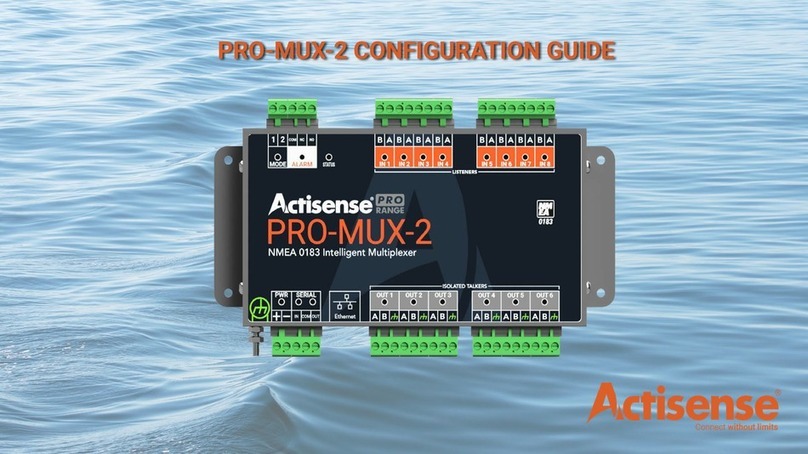
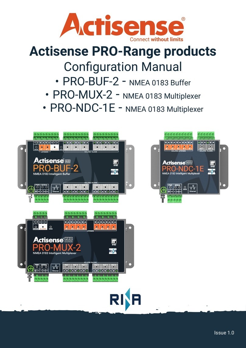
Actisense PRO-MUX-2 Instruction sheet

1Active Research Ltd 2022
Connect without limits
Professional Type Approved
NMEA®0183 Multiplexer
Conguration Manual
Issue 1.0

2Active Research Ltd 2022
Important Notices
The device to which this manual relates
complies with the Electromagnetic Compatibility
requirements according to IEC 60945:2002-08,
DNVGL-CG-0339:2019 & IACS UR E10 Rev7.
The unit should always be used in conjunction
with appropriately approved, shielded cable
and connectors as per NMEA 0400 to ensure
compliance. A declaration of conformity is
available for download at www.actisense.com.
If the device to which this manual relates is to be
installed within ve metres of a compass, please
refer to the ‘Compass Safe Distance’ section in the
‘Technical Specications’ table.
Trademarks and Registered Trademarks
Actisense®and the Actisense logo are registered
trademarks of Active Research Limited (Ltd).
All other trademarks are the property of their
respective owners.
The NMEA®name and NMEA logo are copyright
held by the NMEA. All uses in this manual are by
permission and no claim on the right to the NMEA
name or logo are made in this manual.
Fair Use Statement
The contents of this manual may not be
transferred or copied without the express written
permission of
Active Research Ltd. Copyright © 2021 Active
Research Ltd. All rights reserved.
Technical Accuracy
To the best of our knowledge the information
contained in this document was correct at the
time it was produced. Active Research Ltd cannot
accept liability for any inaccuracies or omissions.
The products described in this manual and the
specications thereof may be changed without
prior notice. Active Research Ltd cannot accept
any liability for differences between the product
and this document. To check for updated
information and specications please check www.
actisense.com.
Active Research Ltd will not be liable for
infringement of copyright, industrial property
rights, or other rights of a third party caused by
the use of information or drawings described in
this manual.
Product Registration
Please register your product via the online form at
https://actisense.com/product-registration
Your product package includes a unit serial
number. The serial number is six digits long and
can be found below the barcode on the label. Your
registration will assist Actisense Support to link
your product to your details, simplifying any future
assistance you may require.
Product Guarantee
All Actisense products are provided with a 5 year
guarantee upon registration. To register your
product, visit https://actisense.com/product-
registration.
If you suspect that the unit is faulty please refer to
the Troubleshooting Section of the User Manual
before
contacting support.
It is a requirement of the guarantee that all
installations of electronic equipment follow the
NMEA 0400 specication. Any connection to a
battery or power supply must meet the mandatory
essential safety requirements that may be
imposed by local regulatory agencies.
Actisense products are intended for use in a
marine environment, primarily for below deck
use. If a product is to be used in a more severe
environment, such use may be considered misuse
under the Active Research Ltd guarantee.
Product Disposal
Please dispose of this product in accordance with
the WEEE Directive. The product should be taken
to a registered establishment for the disposal of
electronic equipment.

3Active Research Ltd 2022
Intelligent Type Approved NMEA Multiplexer - PRO-MUX-2
Contents Page
Introduction.........................................................................................................................................4
PRO-MUX-2 overview........................................................................................................................4
Accessing the PRO-MUX-2 via the network.................................................................................5
The PRO-MUX-2 home page...........................................................................................................6
Information Icon................................................................................................................................6
Status Icon..............................................................................................................................7
Settings Icon.........................................................................................................................10
Planning your NMEA 0183 network.............................................................................................11
Conguring Input from ‘Talkers’.........................................................................................11
Conguring Output to ‘Listeners’.......................................................................................12
Routing of Input and Output Data................................................................................................14
Basic Routing...................................................................................................................................15
Autoswitching..................................................................................................................................16
Advanced Routing.....................................................................................................................17-18
Troubleshooting Guide..................................................................................................................19
Technical Specication............................................................................................................20-21
Dimensioned Drawing....................................................................................................................21

4Active Research Ltd 2022
Introduction
The PRO-MUX-2 is a powerful NMEA 0183 multiplexer/router, capable of advanced ltering, allowing
the user to forward any NMEA0183 data from their installed ‘talkers’ to any other connected ‘listener’
that requires it.
Being a multiplexer, the PRO-MUX-2 allows these incoming data streams from ‘talkers’ to be
combined into a single output stream and fed to a listening device that requires data from multiple
sources at the same time. The baud-rate of reception & transmission is also adjustable making the
device even more exible.
The PRO-MUX-2 allows for two separate methods for conguration.
• Mode pin set-up. This method is covered in the install/user manual.
• In-built conguration tool (the web-based method for conguring your PRO-MUX-2).
This manual cover details of the web-based method for conguring your PRO-MUX-2.
The conguration tool is compatible across all popular Operating Systems.
The PRO-MUX-2 also supports a direct Ethernet connection to a PC without the need for a specialised
ethernet crossover cable.
Please read through this manual carefully to realise the full potential of the PRO-MUX-2.
This manual should be read in conjunction with the user/install manual, available from the Acti-
sense website using the following link:
https://actisense.com/wp-content/uploads/2020/01/PRO-MUX-1-User-Manual-issue-1.00.pdf
PRO-MUX-2 Overview
Mode Pins
Alarm Input
NMEA0183 Inputs from talkers (x8)
Status LED
Grounding Stud
Power
Serial Port
NMEA0183 Outputs to listeners (x6)
Ethernet Port
Mounting Holes
Mounting Holes

5Active Research Ltd 2022
Intelligent Type Approved NMEA Multiplexer - PRO-MUX-2
Accessing the PRO-MUX-2 via the network
The PRO-MUX-2 can be connected to your network in one of two ways.
1: Standard Ethernet Networks
• If the PRO-MUX-2 is connected to an ethernet network containing both DHCP and DNS servers,
launch any of the popular web browsers.
• Replacing ‘xxxxxx’ with the serial number of your PRO-MUX-2, type the following command into
the address bar.
• http://promux-xxxxxx
The home-page for the PRO-MUX-2 will be shown as below.
2: Direct connection or basic ethernet networks
• If the PRO-MUX-2 is connected directly to a PC, or the ethernet network does not have a DHCP
server, the PRO-MUX-2 will communicate using the auto-IP by default.
• The auto-IP process can take up to 60 seconds to complete.
• The PC’s ‘Local Area Connection’ must also be set-up to use auto-IP in order to communicate on
this network. Most PC’s are set-up to do this by default. If needed, instructions on how to do this
using Windows 10 are given in the user/install manual (other Windows operating systems will be
similar).
https://actisense.com/wp-content/uploads/2020/01/PRO-MUX-1-User-Manual-issue-1.00.pdf
• NOTE: Administrator privileges are required to carry out these modications.
• Once the PC and PRO-MUX-2 are using the same IP address range, launch any popular web
browser.
• Replacing ‘xxxxxx’ below with the serial number of your PRO-MUX-2, type in the following com-
mand into the address bar.
• http://promux-xxxxxx
The home-page for the PRO-MUX-2 will be as shown below.
NOTE: Clicking on any of the icons at this point will allow you to view the current settings of your
PRO_MUX-2, but alterations are not possible until a user ‘Login’ is performed.
When prompted, please use Username: admin & Password: admin. The password can be altered
later. The username ‘admin’ is static and cannot be altered.

6Active Research Ltd 2022
Navigating the PRO-MUX-2 home-page
Information Icon
• This icon will display all the relevant technical information relating to the device itself.
• This information is important if you need to troubleshoot your device or require technical
assistance at a future date.

7Active Research Ltd 2022
Intelligent Type Approved NMEA Multiplexer - PRO-MUX-2
Status Icon
• This icon displays the current status of all the various user controlled settings:
• Data Servers: Displays the following information relating to the data server if enabled.
• Serial: Displays the current status of all the serial ports, including their baud rate, alias name if
applied, port direction and the current data load on each port.

8Active Research Ltd 2022
• Detailed Stats: Once the PRO-MUX-2 is operational, this page will show the number of individ-
ual sentences being received or transmitted over a 10 second period. The picture below shows
a simple case of GPS sentences being sent and received. Once the PRO-MUX-2 has more inputs
and outputs enabled this will contain all the sentences being routed through the device.
• Messages being received from talkers
• Messages being transmitted to listeners

9Active Research Ltd 2022
Intelligent Type Approved NMEA Multiplexer - PRO-MUX-2
• Routing: Matrix showing data ow between inputs and outputs
• Alarms: Shows the status of any alarms which are currently set

10 Active Research Ltd 2022
Settings Icon
• Provides access to the device for conguration.
• Using any of these setting requires that the user ‘Login’ to the device (see page 5).
• The settings page provides the following functionality:
Administration:
Facility to change password only (Username is always ‘admin’)
Facility to re-start device.
Firmware Update:
Details current rmware version and provides the facility to update.
Network:
Allows the network to be congured correctly depending upon your particular set-up.
Operating mode:
Allows any pre-congured modes to be selected.
Reset Password:
Password can be reset to factory default
Alarms:
Allows the user to set up any required alarms.
Data Server:
Provides facility to turn server on/off as well as specifying data format output, direction and
output protocol.
Routing:
Main conguration table to allow precise routing of data between inputs an outputs.
Access to ‘autoswitch’ operation and set-up.
Serial:
Allows full conguration for each port including baud rate setting, data direction, an ‘alias’
naming facility and also shows the current data load on each port.

11 Active Research Ltd 2022
Intelligent Type Approved NMEA Multiplexer - PRO-MUX-2
Planning your NMEA0183 network
• Your PRO-MUX-2 allows you to input data from a maximum of 8 ‘talkers’ and direct these signals
either individually, or in combination with other signals, to the various output ports which the PRO-
MUX-2 provides (Output ports(x6)/Data server(x1)/Serial Port(x1)).
• In order for this to work correctly, the PRO-MUX-2 must know at what baud rate the connected
device is running. It is helpful to be able to name each device separately, so a facility to do this is
provided.
Conguring Input from ‘Talkers’
• Please read this section in conjunction with the install/user manual if unsure of the required steps
• Adding a ‘talker’ device is a straight forward process.
• Connect your NMEA 0183 ‘talker’ to one of the ‘Listener’ ports on the PRO-MUX-2 (see Page 4).
• Pay attention to the wire-colours if your device follows the NMEA 0183 standard.
• Connect the ‘talker’ pair of wires from your device to your PRO-MUX-2.
• Congure the device from within ‘Serial Settings’ of the conguration tool.
• Give the device a useful/meaningful name for future reference by lling in the blank ‘Name’ box
next to its input.
As an example below, we have installed an AIS unit/two GPS units and a Speed sensor to the rst
four inputs of the PRO-MUX-2.
We have set the baud rate (speed) of the AIS unit to 38400, which is the usual rate for an AIS unit. The
remaining three devices have all been set to 4800 baud.
NOTE: The rst four inputs of the PRO-MUX-2 can be set to ‘auto-baud’ between 4800 & 38400 if re-
quired. Auto-baud allows the PRO-MUX-2 to follow the baud rate of the connected talker, without the
need to specify it. This is helpful if you are unsure of the ‘talker’ baud rate, or it can change during its
normal operation. Inputs 5-8 are pre-set to 4800 baud only.
Manual /
Autobaud

12 Active Research Ltd 2022
Conguring Output to ‘Listeners’
• Conguring outputs from the PRO-MUX-2 is performed in a similar way to conguring inputs.
• Connect the NMEA 0183 ‘listener’ to one of the ‘talker’ ports on the PRO-MUX-2. (see page 4)
• Pay attention to the wire-colours if your device follows the NMEA 0183 standard.
• Connect the ‘listener’ pair of wires from your device to your PRO-MUX-2
• Congure the device from within the ‘Serial Settings’ of the conguration tool.
• Give the output stream a useful/meaningful name for future reference as shown previously.
As an example below, we have installed an NGW-1-ISO, a Radar and an Autopilot to the rst three out-
puts of the PRO-MUX-2.
We have set the baud rate (speed) of the NGW-1-ISO unit to 38400 baud. The remaining devices have
been set to 4800.
Consult the manuals and datasheets for your individual devices to nd the correct settings.
To conrm any changes made to the INPUTS and OUTPUTS on the PRO-MUX-2, click on the Serial tab
of the ‘Status’ page.
The setting made above will result in the following page being displayed (p.13)

13 Active Research Ltd 2022
Intelligent Type Approved NMEA Multiplexer - PRO-MUX-2
Serial ‘Status’ conrmation
• Below is the current state of INPUTS and OUTPUTS based on the previous examples.
• With real devices connected and ‘talking’ to the network, there would be an indication of ‘Load’
displayed as well.
Load Indicator
• Once the PRO-MUX-2 is operational and combining data, each port in use will give an indictation
of its current ‘load’ and sentences being passed as shown below.
• Please refer to the ‘trouble-shooting guide’ on page 19 for details of the ‘STATUS’ light indicator
which will alter colour if sentences are being dropped / lost due to ‘overload’ conditions being
reached.

14 Active Research Ltd 2022
Routing of INPUTS to OUTPUTS
• Once the required ‘talkers and ‘listeners’ are connected to the PRO-MUX-2, you need to decide
how you wish the various input signals to be routed and/or combined to the required outputs.
• When implementing this routing plan, there are baud rate issues that need to be considered.
• An input signal being received at 4800 baud will not be output 4x faster if the output baud rate
is set to 38400 baud. The PRO-MUX-2 cannot replicate the messages it receives. The input signal
of 4800 baud can be output at 38400 baud, but not repeated any faster than the original 4800
input baud rate frequency.
• An input signal being received at 38400 baud will result in a loss of data if it is tied to an output
baud rate rate lower than the input. If the rate of messages being received is faster than the out-
put port can transmit them, this will lead to signal loss, and sentences being dropped. This is quite
a common scenario and is not necessarily an issue if its implications are understood.
The Routing Matrix
Shown below is the routing matrix for the PRO-MUX-2.
• The inputs for the PRO-MUX-2 are located on the LHS of the matrix table.
• The outputs from the PRO-MUX-2 are shown on the horizontal orange bar.
• DS1(IP) input/output relates to the Ethernet port.
• ASW1 & ASW-2 provide access to the auto-switching functionality. These are inactive when au-
to-switching is not being used.

15 Active Research Ltd 2022
Basic Routing
• The basic routing of signals is a straight forward process of connecting inputs and outputs in the
matrix table.
• Inputs and outputs are connected by setting or clearing the point where they cross in the table.
• As an example setting (shown below) the following routing connections have been made.
• OUT-6 - Taking a feed from IN-2 and IN-7
• OUT-5 - Taking a feed from IN-2 and IN-7
• OUT-4 - Taking a feed from IN-1 and IN-7
• OUT-3 - Taking a feed from IN-5 only
• OUT-2 - Taking a feed from IN-3 and IN-5
• OUT-1 - taking a feed from IN-3 only
From your browser window, simply click the X at the point where the required routing is required.
This will change it to a tick as shown, indicating that data will be passed between this Input and Out-
put.
Note: Pressing the “tick” or X on the orange bar will quickly toggle all connections ON or OFF.
Intelligent Type Approved NMEA Multiplexer - PRO-MUX-2

16 Active Research Ltd 2022
Auto-switching
• For marine systems that have multiple NMEA devices of an identical type (e.g. two GPS’s or two
depth sounders), automatic selection of the highest priority device with valid data is very im-
portant. However, the NMEA 0183 standard has no method of automatically switching between
different devices, so this requirement is usually fullled with a manual changeover switch.
• The PRO-MUX-2 has the provision for auto-switching on two devices, where the incoming signal
can be prioritised in case of signal loss on one of the channels.
• In practise, this means that should the signal on your GPS(1) be interrupted due to a malfunction
of the GPS unit, the auto-switching facility will detect this and the signal from GPS(2) will automat-
ically replace it, giving you a seamless continuation of your data.
• The PRO-MUX-2 allows for auto-switching of two devices (eg. GPS’s(x2) & Depth sounders(x2)).
• Any NMEA 0183 device can be auto-switched if required.
Auto-switch routing
• The auto-switch is congured in software to act as in INPUT even though it does not have a physi-
cal direct input of its own. It is often described as a “virtual input.”
• To congure the ASW mode, you need to decide which two physical inputs require to be
auto-switched. It is very common to auto-switch a GPS signal, so the following description will
assume that a GPS unit is attached to IN-1 and IN-2 as an example.
• From within the routing matrix, enable ASW1 with the slider at the top of the window. This will
change the ASW1 output row at the bottom of the screen to be active.
• Press “Add” and select which of the physical inputs you would like to be the primary GPS source.
• Repeat the above step, and add which GPS input will be the secondary source, auto-switching
should the primary GPS fail.
• On the active ASW-1 row at the bottom, select which output you require the auto-switched signal
to be fed to (in this example OUT-1 is used). The ASW-1 will now feed IN-1 to OUT-1, and in the
event of IN-1 failing, will autoswitch to feeding IN-2 to OUT-1.
• NOTE: In the main matrix, DO NOT also feed IN-1 & IN-2 to OUT-1. This will by-pass the auto-switch
functionality. Leave these as X. IN-1 & IN-2 can however still be used to feed other outputs.

17 Active Research Ltd 2022
Advanced Routing
• Advanced routing is a feature which allows the user to select which messages within an 0183
data stream are allowed to pass to the output and which sentences are not transmitted.
• It is an ideal feature if you only require certain sentences passed to increase the message band-
width.
• As an example of how this feature works, we have set up a feed from IN-1 to OUT-1 with a data
stream containing 5 different 0183 sentences.
• These sentences contain GPGGA, GPGSA, GPGSV, PGVTG & GPZDA.
• On feeding this data into IN-1 and out from OUT-1 the following message stream would be availa-
ble.
• On viewing the Routing Settings page, shown below, clicking on the ‘+’ sign at the RHS in the ‘“Ad-
vanced” column will display all of the message headers that this stream contains.
Intelligent Type Approved NMEA Multiplexer - PRO-MUX-2

18 Active Research Ltd 2022
Advanced Routing(cont’d)
• If you wish, for example, to only allow sentence GPGGA to pass through to OUT-1, you need to
perform the following three steps:
1: Enable the required message with the slider on the RHS (in this case GPGGA).
2: Disable the IN-1 to OUT-1 FULL data stream.This stops the entire stream being transmitted.
3: Enable the required message stream from within the header window. (Tick beside GPGGA only).
• The setting shown above will automatically transmit GPGGA, and reject all other sentences from
this data stream (as shown below). There is a small delay as buffers are emptied.
• You are free to select other sentences for transmission, or by selecting all but one sentence, you
can reject an individual sentence if required.
• Only GPGGA now transmitted.

19 Active Research Ltd 2022
Intelligent Type Approved NMEA Multiplexer - PRO-MUX-2
Troubleshooting Guide
First level PRO-MUX-2 diagnostics / fault nding can be performed by observing the LED behaviour.
The normal behaviour of the PRO-MUX-2 LEDs is described on the next page. If the LEDs are not
behaving as expected, this will indicate a fault in either the device connected to the PRO-MUX-2, the
wiring/connections, or the PRO-MUX-2 itself.
Some common checks to perform on all terminals of the PRO-MUX-2 if the correct LED behaviour is
not displayed:
• Connectors are fully inserted
• All pins of the connector are in the correct location (not overlapping into another port position)
• Wires are terminated rmly and correctly (check polarity)
LED Colour State Description User action
PWR Blue Pulsing Indicates presence of power None required
IN (INCLUDING
‘SERIAL IN’)
Green Flashing Data available on input indicated by LED. No action required
-O No data available on this input or autobaud
detection in progress (up to 20 seconds)
Check if connected Talker is sending
data. If it is, review conguration.
OUT (INCLUDING
‘SERIAL OUT’) Orange Flashing/ solid
Flashes at a rate determined by baud rate and
data length. If available bandwidth is nearly full,
LED may appear solid instead of ashing
None required
STATUS
Red Flashing / solid Buer Full – Overload condition, sentences are
being dropped.
Use a web browser to review congura-
tion and correct overload condition.
Yellow Flashing / solid
Warning, buer is lling. Duplicate deletion is
managing to maintain output capacity by delet-
ing older copies of sentences
Review conguration to understand the
required rates of sentences which is
acceptable to any connected device
Green Flashing / solid Normal operation. No data issues. No action required
-O
No data passing through outputs. Either no
input data, or if IN LED is active it means all
data is blocked.
Check if the connected Talker is sending
data. If it is, review conguration.
Ethernet
Green Flashing Data activity on the Ethernet port No action required
Yellow On Indicates line speed at 100Mbps No action required
O Indicates line speed at 10Mbps
-O No data available Check that the Ethernet network is oper-
ational.
ALARM Red On Indicates alarm conditions have been met. Review status page in browser to under-
stand alarm source.
MODE Green Pulsing / Flashing
Pulsing - User dened mode selected,
Flashing - Pre-dened operating mode select-
ed according to mode pins. Number of ashes
= operating mode number
No action required
PWR and STATUS
(Combined)
Power = blue
Status = red
Power = on (solid)
Status = on (solid)
Critical HW Error Both Power & Status LEDs
are solid
Return to manufacturer if this persists
after a power reset

20 Active Research Ltd 2022
Technical Specication
Power Supply
Input Supply Voltage 10 to 35 V DC
Input Supply Current 220mA max @ 12V DC (all outputs @ full drive into 100 ohm loads)
Input Protection Continuous reverse polarity, transient overvoltage and ESD protection
Power Indicator LED, Blue - indicates unit is functioning correctly
Input Supply Connector Pluggable 2-way screw terminal, 5.08mm pitch (12 to 30 AWG)
NMEA 0183 Port - Listener & Talker
Number of Listener / Input Ports 8 isolated NMEA 0183 Listeners
Number of Talker / Output Ports 6 isolated NMEA 0183 Talkers
Compatibility Fully NMEA 0183, RS422 & RS232 compatible. RS485 Listener compatible
Speed / baud rate 4800 to 38400 bps
Talker Output Voltage Drive >= 2.2V (differential) into 100 ohm
Talker Output Current Drive 20 mA maximum per output
Talker Output Protection Short circuit and ESD
Talker Data Indicator LED, Orange (Flashes at data rate)
Listener Input Voltage Tolerance -15 V to +15 V continuous, -35 V to +35 V short term (< 1 second)
Listener Input Protection Current limited, overdrive protection to 40 VDC and ESD protection
Listener Data Indicator LED, Green (Flashes to indicate valid input)
Connectors Pluggable 2/3-way screw terminals, 5.08mm pitch (12 to 30 AWG)
Serial Port
Compatibility RS422 & RS232 compatible. RS485 Listener compatible
Speed / baud rate 4800 to 115200 bps
Output Voltage Drive >= 2.1V (differential) into 100 ohm
Output Current Drive 20 mA max.
Output Protection Short circuit and ESD
Input Voltage Tolerance -15 V to +15 V continuous, -35 V to +35 V short term (< 1 second)
Input Protection Current limited, overdrive protection to 40 VDC and ESD protection
Data Indicators LED’s: Green = Receive, Orange = Transmit
Connectors Pluggable 3-way screw terminals, 5.08mm pitch (12 to 30 AWG)
Ethernet Port
Host Interface 10/100BaseT, automatic polarity detection
Supported Protocols
TCP/IP for conguration and rmware updating
TCP/IP and UDP for NMEA 0183 comms
Indicators Green = Link/Activity, Yellow = 100 Mbps
Connector RJ45
Isolation
NMEA 0183 Listener OPTO-Isolated, Hi-Pot tested to 1000V
NMEA 0183 Talker Uses IsoDrive™, Hi-Pot tested to 1000V
Serial Port Uses IsoDrive™, Hi-Pot tested to 1000V
Alarm Relay Hi-Pot tested to 1000V
Ethernet Port 2kV for 60s
Other manuals for PRO-MUX-2
2
Table of contents
Other Actisense Multiplexer manuals

Actisense
Actisense PRO-MUX-1 User manual

Actisense
Actisense NDC-4 User manual

Actisense
Actisense PRO-MUX-2 User manual

Actisense
Actisense NMEA 0183 User manual

Actisense
Actisense PRO-MUX-2 User manual

Actisense
Actisense NDC-4 User manual

Actisense
Actisense NDC-5 User manual

Actisense
Actisense NMEA 0183 User manual

Actisense
Actisense PRO-NDC-1E User manual

Actisense
Actisense PRO-BUF-2 Instruction sheet