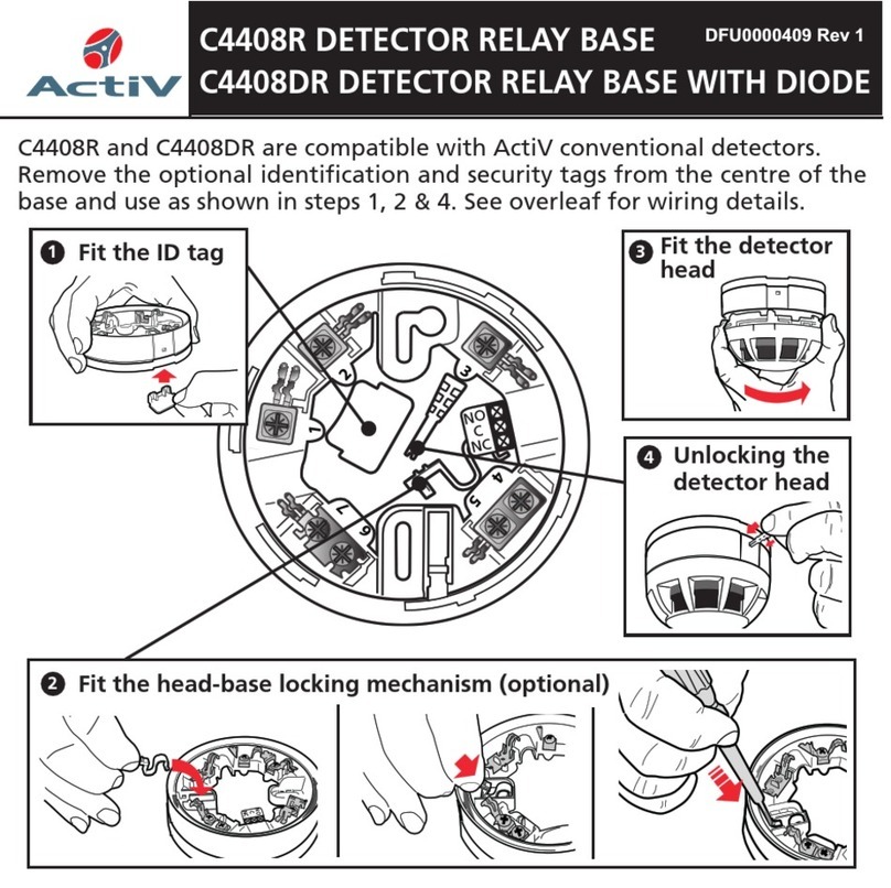
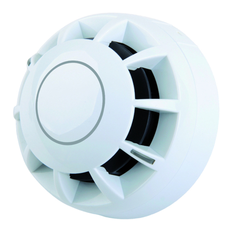
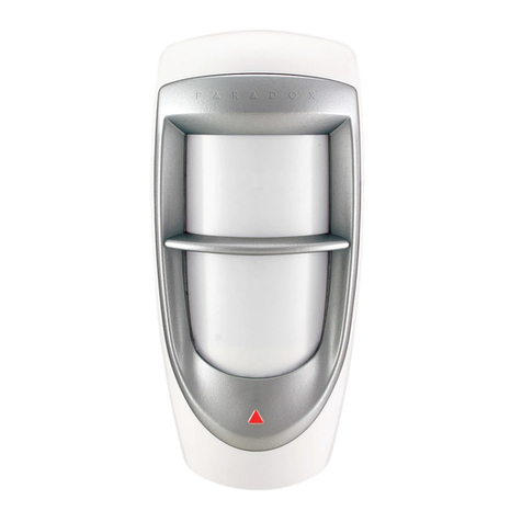
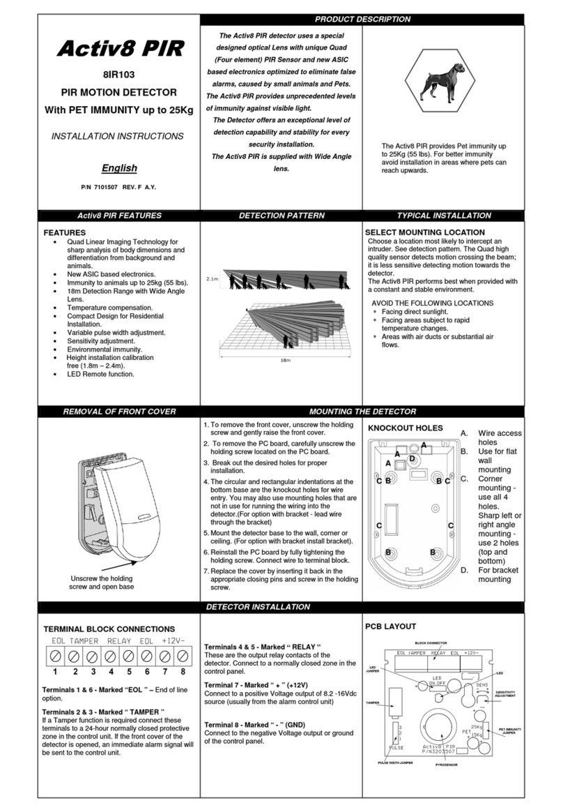
ActiV C4408 User manual
Other ActiV Security Sensor manuals
Popular Security Sensor manuals by other brands
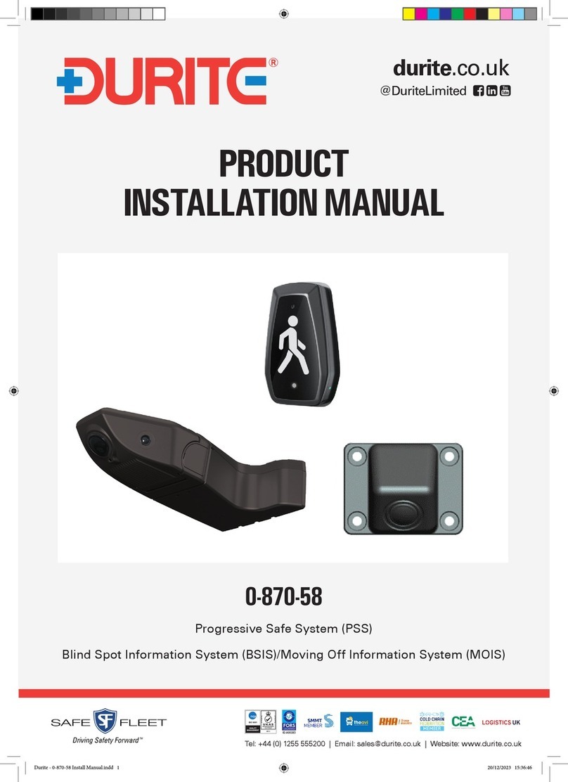
Durite
Durite 0-870-58 Product installation manual
PCB Piezotronics
PCB Piezotronics IMI SENSORS TO640B30 Installation and operating manual
Refco
Refco Startek operating manual
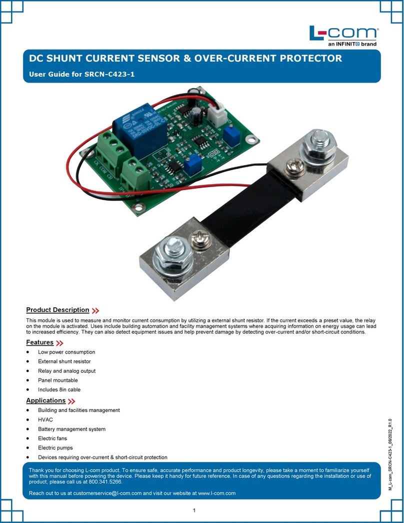
Infinite
Infinite L-com SRCN-C423-1 user guide

BEA
BEA LZR- FLATSCAN REV-PZ user guide
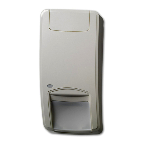
Interlogix
Interlogix DD1012AM-D Installation sheet

ParTech
ParTech SludgeWatch 8200w2 instruction manual
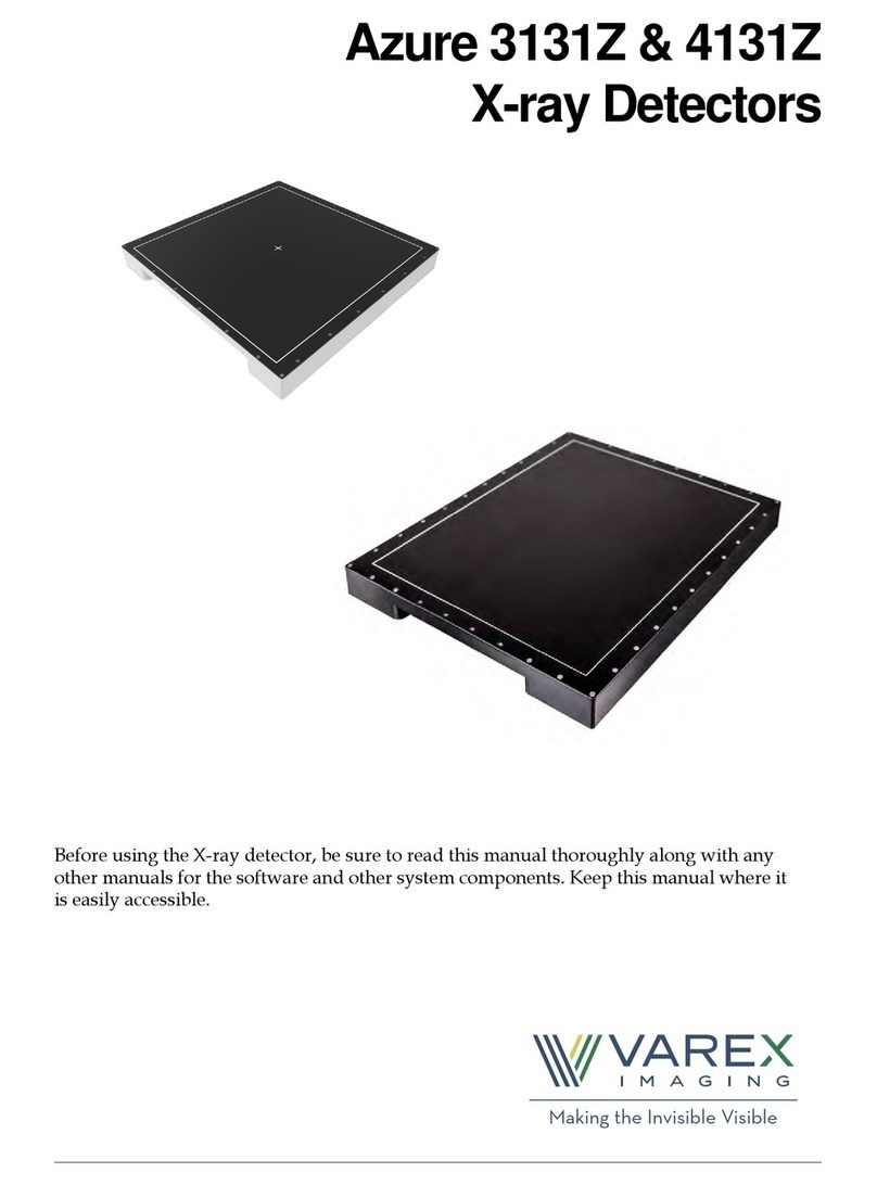
Varex Imaging
Varex Imaging Azure 3131Z manual
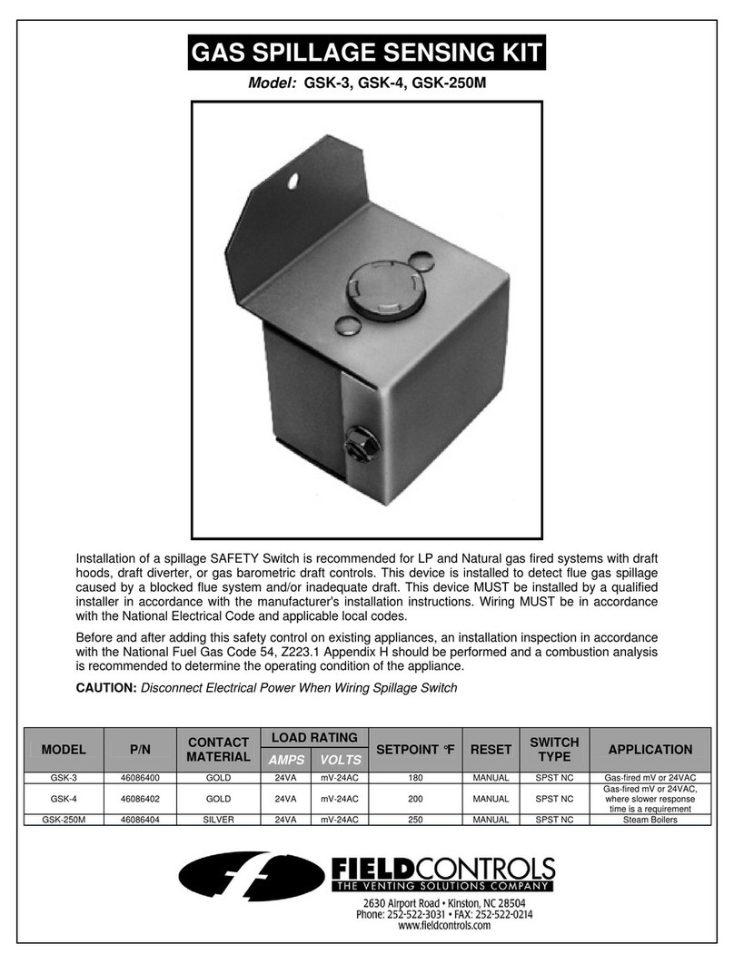
Field Controls
Field Controls Gas Spillage Sensing Kit GSK-250M instruction manual
YOKOGAWA
YOKOGAWA TB830D Start-up
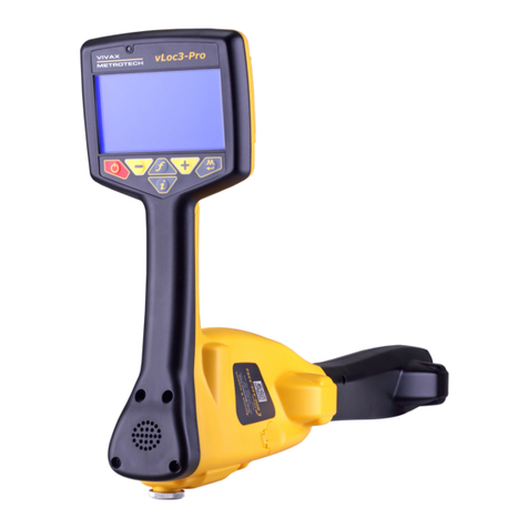
Vivax Metrotech
Vivax Metrotech vLoc3 Series user guide
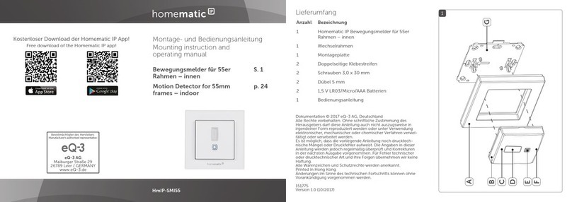
Homematic IP
Homematic IP HmIP-SMI55 Mounting instruction and operating manual


