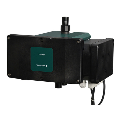
YOKOGAWA TB830D Installation manual

User’s
Manual TB830D
Surface Scattering Light Turbidity
Detector
Start-up and Safety Precautions
IM 12E04B40-01EN
IM 12E04B40-01EN
1st Edition

2
IM 12E04B40-01EN 1st Edition : Mar. 08, 2023-00
uIntroduction
Thank you for purchasing TB830D Surface Scattering Light Turbidity Detector.
This User’s Manual contains all essential information for the user to make full use of TB830D.
Please read the following respective documents before installing and using the instrument.
The related documents are listed as follows.
General Specications
Contents Document number Note
TB830D, FLXA402T Surface Scattering
Light Turbidity Detector GS 12E04B40-01EN Online manual
“EN” in the document number is the language code.
User’s Manual
Contents Document number Note
TB830D Surface Scattering Light
Turbidity Detector
Start-up and Safety Precautions
IM 12E04B40-01EN Attached to the product (printed manual)
(This manual)
TB830D Surface Scattering Light
Turbidity Detector IM 12E04B40-02EN Online manual
FLXA402T Liquid Analyzer for Turbidity
and Chlorine
Start-up and Safety Precautions
IM 12A01G01-01EN Attached to the product (printed manual)
FLXA402T Liquid Analyzer for Turbidity
and Chlorine
Installation and Wiring
IM 12A01G01-02EN Online manual
FLXA402T Liquid Analyzer for Turbidity
and Chlorine
Operation of Converter
IM 12A01G01-03EN Online manual
FLXA402T Liquid Analyzer for Turbidity
and Chlorine
Operation of pH
IM 12A01G02-01EN Online manual
FLXA402T Liquid Analyzer for Turbidity
and Chlorine
Operation of SC
IM 12A01G03-01EN Online manual
“EN” in the document number is the language code.
An exclusive User’s Manual might be attached to the products whose sux codes or option codes
contain the code “Z” (made to customers’ specications). Please read it along with this manual.
Technical Information
Contents Document number Note
FLXA402T Liquid Analyzer for Turbidity
and Chlorine
MODBUS Communication
TI 12A01G01-62EN Online manual
“EN” in the document number is the language code.
You can download the latest documents from our website. Scan QR code.
http://www.yokogawa.com/an/xa402t/download/
Refer to each corresponding manual for other related products.
No. IM 12E04B40-01EN 1st Edition : Mar. 2023 (YK)
All Rights Reserved Copyright © 2023, Yokogawa Electric Corporation

3
IM 12E04B40-01EN 1st Edition : Mar. 08, 2023-00
nNotes on Handling User’s Manuals
• Please hand over the user’s manuals to your end users so that they can keep the user’s
manuals on hand for convenient reference.
• Please read the information thoroughly before using the product.
• The purpose of these user’s manuals is not to warrant that the product is well suited to any
particular purpose but rather to describe the functional details of the product.
• No part of the user’s manuals may be transferred or reproduced without prior written
consent from YOKOGAWA.
• YOKOGAWA reserves the right to make improvements in the user’s manuals and product at
any time, without notice or obligation.
• If you have any questions, or you nd mistakes or omissions in the user’s manuals, please
contact our sales representative or your local distributor.
nDrawing Conventions
Some drawings may be partially emphasized, simplied, or omitted, for the convenience of
description.
Some screen images depicted in the user’s manual may have dierent display positions or
character types (e.g., the upper / lower case). Also note that some of the images contained in this
user’s manual are display examples.
nTrademark Acknowledgements
• FLEXA, FLXA and SENCOM are trademarks or registered trademarks of Yokogawa Electric
Corporation.
• All other company and product names mentioned in this user’s manual are trademarks or
registered trademarks of their respective companies.
• We do not use TM or ® mark to indicate those trademarks or registered trademarks in this
user’s manual.
nProduct Disposal
The instrument should be disposed of in accordance with local and national legislation/regulations.
nWarranty and service
Yokogawa products and parts are guaranteed free from defects in workmanship and material
under normal use and service for a period of (typically) 12 months from the date of shipment from
the manufacturer.
Individual sales organizations can deviate from the typical warranty period, and the conditions of
sale relating to the original purchase order should be consulted. Damage caused by wear and
tear, inadequate maintenance, corrosion, or by the eects of chemical processes are excluded
from this warranty coverage.
In the event of warranty claim, the defective goods should be sent (freight paid) to the service
department of the relevant sales organization for repair or replacement (at Yokogawa discretion).
The following information must be included in the letter accompanying the returned goods:
• Part number, model code and serial number
• Original purchase order and date
• Length of time in service and a description of the process
• Description of the fault, and the circumstances of failure
• Process/environmental conditions that may be related to the failure of the device.
• A statement whether warranty or non-warranty service is requested
• Complete shipping and billing instructions for return of material, plus the name and phone
number of a contact person who can be reached for further information.
Returned goods that have been in contact with process uids must be decontaminated/
disinfected before shipment. Goods should carry a certicate to this eect, for the health and
safety of our employees.
Material safety data sheets should also be included for all components of the processes to which
the equipment has been exposed.Read this User’s Manual before operating TB830D to make full
use of the function.
Throughout this user’s manual, you will nd several dierent types of caution or warnings. Follow
the cautious message for safety precautions.

4
IM 12E04B40-01EN 1st Edition : Mar. 08, 2023-00
uCE marking products
nAuthorized Representative in the EEA and the Importer into the EU/
EEA Market
The Authorized Representative for this product in the EEA and the importer for this product into
the EU/EEA market via Yokogawa sale channel is:
Yokogawa Europe B.V.
Euroweg 2, 3825 HD Amersfoort, The Netherlands
nImporter for This Product into the Great Britain Market
In relation to UKCA marking, the importer for this product into the Great Britain market via the
YOKOGAWA sales channel is :
Yokogawa United Kingdom Limited
Stuart Road Manor Park Runcorn, WA7 1TR, United Kingdom
n Identication Tag
This manual and the identication tag attached on packing box are essential parts of the product.
Keep them together in a safe place for future reference.
nUsers
This product is designed to be used by a person with specialized knowledge.
uSafety Precautions
WARNING
Installation and wiring
The TB830D should only be used with equipment that meets the relevant IEC, American or
Canadian standards.
Yokogawa accepts no responsibility for the misuse of this unit.
Don’t install “general purpose type” instruments in the hazardous area.
Do not use an abrasive or organic solvent in cleaning the instrument.
Electrostatic discharge
The TB830D contains devices that can be damaged by electrostatic discharge. When servicing
this equipment, please observe proper procedures to prevent such damage. Replacement
components should be shipped in anti-static packaging. Repair work should be done at grounded
workstations using grounded soldering irons and wrist straps to avoid electrostatic discharge.
CAUTION
The Instrument is packed carefully with shock absorbing materials, nevertheless, the instrument
may be damaged or broken if subjected to strong shock, such as if the instrument is dropped.
Handle with care.
This instrument is a Class A product, and it is designed for use in the industrial environment.
Please use this instrument in the industrial environment only.
When you open the front cover, make sure the screws are completely out of the screw holes, and
then open the front cover slowly in order not to damage the threaded parts on the housing. If the
threaded parts are damaged and the screws cannot be tightened, the waterproof performance
will deteriorate.

5
IM 12E04B40-01EN 1st Edition : Mar. 08, 2023-00
n Safety, Protection, and Modication of the Product
• In order to protect the system controlled by the product and the product itself and ensure
safe operation, observe the safety precautions described in this user’s manual. We assume
no liability for safety if users fail to observe these instructions when operating the product.
• If this instrument is used in a manner not specied in this user’s manual, the protection
provided by this instrument may be impaired.
• If any protection or safety circuit is required for the system controlled by the product or for
the product itself, prepare it separately.
• Be sure to use the spare parts approved by Yokogawa Electric Corporation (hereafter
simply referred to as YOKOGAWA) when replacing parts or consumables.
• Modication of the product is strictly prohibited.
• The following safety symbols are used on the product as well as in this manual.
WARNING
This symbol indicates that an operator must follow the instructions laid out in this manual in order
to avoid the risks, for the human body, of injury, electric shock, or fatalities. The manual describes
what special care the operator must take to avoid such risks.
CAUTION
This symbol indicates that the operator must refer to the instructions in this manual in order to
prevent the instrument (hardware) or software from being damaged, or a system failure from
occurring.
CAUTION
This symbol gives information essential for understanding the operations and functions.
NOTE
This symbol indicates information that complements the present topic.
This symbol indicates Protective Ground Terminal.
nWarning and Disclaimer
The product is provided on an “as is” basis. YOKOGAWA shall have neither liability nor
responsibility to any person or entity with respect to any direct or indirect loss or damage arising
from using the product or any defect of the product that YOKOGAWA can not predict in advance.

6
IM 12E04B40-01EN
u
Control of Pollution Caused by the Product
This is an explanation for the product based on “Control of Pollution caused by Electronic
Information Products” in the People’s Republic of China.
产品中有害物质的名称及含量
部件名称
有害物质
铅
(Pb) 汞
(Hg) 镉
(Cd) 六价铬
(Cr (VI)) 多溴联苯
(PBB) 多溴二苯醚
(PBDE)
外壳(金属) ×○○○○○
外壳(塑料) ×○○○○○
印刷电路板组件 ×○○○○○
○: 表示该有害物质在该部件中所有均质材料中的含有量都在GB/T26572所规定的限量要求以下。
×: 表示该有害物质至少在该部件的某一均质材料中的含有量超出GB/T26572所规定的限量要求。
环保使用期限: 这个标志是基于SJ/T11364,在中国(不包括台湾,香港,澳门)贩售的电子电
器产品所适用的环保使用期限。
只要遵守产品上关于安全及使用上的注意事项,从制造之日起计算在该年限
内,不会发生制品内的有害物质外泄,突然变异,对环境或人体以及财产产生
重大影响的情况。
(注) 该年限是《环境保护使用期限》,不是产品的保质期限。
另外,关于替换部件的推荐替换周期,请阅读使用说明书。
uCompliant Standards
Safety (*1):
UL: UL 61010-1, UL 61010-2-030
CSA: CAN/CSA-C22.2 No.61010-1
CAN/CSA-C22.2 No.61010-2-030
CE, UKCA: EN 61010-1, EN 61010-2-030
Morocco/LVD Arrêté: NM EN 61010 1, NM EN 61010 2 030
GB: GB30439
Installation altitude: 2000 m or less
Overvoltage Category based on IEC 61010: II(*)
Pollution level: IEC 61010: 2 (**)
(*) Installation category, called over-voltage category, species impulse withstand voltage. Equipment with Category II is energy-
consuming equipment to be supplied from the xed installation.
(**) Pollution level shows the level of existing the solid, liquid and gas which break electrical isolation. Category 2 is applied to
normal room environment.
EMC:
CE, UKCA:
EN 61326-1 Class A,Table 2 (For use in industrial locations)
EN 61326-2-3
EN IEC 61000-3-2
EN 61000-3-2
EN 61000-3-3
Morocco/EMC Arrêté: NM EN 61326 1
NM EN 61326 2 3
NM EN 61000 3 2
NM EN 61000 3 3
RCM: EN61326-1 Class A
Korea Electromagnetic Conformity Standard
한국 전자파적합성 기준 Class A
Environmental regulation:
RoHS Directive (*2): EN IEC 63000
REACH: Regulation EC 1907/2006
Waste Electrical and Electronic Equipment (WEEE) Directive :
This product is purposely designed to be used in a large scale xed installations only and,
therefore, is out of scope of the WEEE Directive. The WEEE Directive does not apply.
The WEEE Directive is only valid in the EU and UK.
(*1): Except for sampling system (-A2, -A3)
(*2): Except for sampling system (-A1, -A2, -A3)
1st Edition : Mar. 09, 2023-01

<Start-up and Safety Precautions> 7
IM 12E04B40-01EN 1st Edition : Mar. 08, 2023-00
1. Instrument Check
Upon delivery, unpack the instrument carefully and inspect it to ensure that it was not damaged
during shipment. If damage is found, retain the original packing materials (including the outer
box) and then immediately notify the carrier and the relevant Yokogawa sales oce.
Make sure the model and sux code on the nameplate match your order and the necessary
accessories are included.
n Model & Sux Codes
TB830D Surface Scattering Light Turbidity Detector
Model Sux code
Option
code
Description
TB830D ········································· ·········· Surface Scattering Light Turbidity Detector
Light source
and Turbidity
standard
-F8
-FS
··········
··········
White LED, Formazin, 0-2 NTU to 0-2000 NTU
860 nm, Formazin, 0-2 FNU/NTU to 0-2000 FNU/NTU
Type -AB
-AD
-AG
-AJ
··········
··········
··········
··········
General purpose for CE, RCM, China standard
General purpose for CSA
General purpose for KC
General purpose
Sampling system -NN
-A1
-A2
-A3
-A5
··········
··········
··········
··········
··········
Without sampling system
With sampling system (without automatic cleaning, without
automatic zero calibration)
With sampling system (with automatic cleaning, without
automatic zero calibration)
With sampling system (with automatic cleaning, with automatic
zero calibration)
Without sampling system, with relay box
Material and Connection
of Sampling system
-AN
-SN
-AD
-AB
-SD
-SB
··········
··········
··········
··········
··········
··········
Without sampling system (Detector mounting bracket Carbon steel)
Without sampling system (Detector mounting bracket Stainless steel)
Carbon steel stanchion, base mounting
Carbon steel stanchion, rear mounting
Stainless steel stanchion, base mounting
Stainless steel stanchion, rear mounting
Solenoid valve for Sampling
system
-NN
-10
-12
-20
-22
··········
··········
··········
··········
··········
Without Solenoid valve
100 V AC
110 V AC
200 V AC
220 V AC
—-NN ·········· Always -NN
Option /L02
/L03
/L05
/L10
/L20
/SCT
/U
/R
/CB
/CD
/CF
/ARS
/PHN7
/PHU7
/TT3
/FC
/PHN2
/PHU2
/L
Connection cable for analyzer 2 m
Connection cable for analyzer 3 m
Connection cable for analyzer 5 m
Connection cable for analyzer 10 m
Connection cable for analyzer 20 m
Stainless steel tag plate
Pipe mounting hardware (SUS)
Rack or wall mounting hardware (SUS)
Conduit adapter G1/2×1 pcs
Conduit adapter 1/2NPT× 1 pcs
Conduit adapter M20×1.5×1 pcs
With arrester
With pH (Using FLXA402) (without ultrasonic cleaning)
With pH (Using FLXA402) (with ultrasonic cleaning)
With 500ml KCl reserve tank for pH
With Free Available Chlorine Analyzer
With pH (Using FLXA402T 2nd input) (without ultrasonic cleaning)
With pH (Using FLXA402T 2nd input) (with ultrasonic cleaning)
Air denoising for Low Range

<Start-up and Safety Precautions> 8
IM 12E04B40-01EN 1st Edition : Mar. 08, 2023-00
Accessories
Name Q´ty Remarks
Silicone cloth 14 pcs/Q’ty (Part number: K9657RJ)
Check tool 1―
Desiccant 1For spare. 4 pcs/Q'ty (Part number: K9657RU)
Desiccant 1For operation. 4 pcs/Q'ty (Part number: K9657RU)
(When the code for “Without sampling” is specied)
Pipe mounting hardware
(Option)
1For “/P” (Option)
Rack mounting hardware
(Option)
1For “/R” (Option)
Soft vinyl chloride tube
(Ø33 × Ø25 Black)
1 set (1 m x 2) For piping detector
(when the code for “Without sampling” is specied)
Clamp 1For piping detector
(when the code for “Without sampling” is specied
2. Wiring and Installation
For details, refer to the User’s Manual IM 12E01B30-02EN.
2.1 Installation Site
Select an installation site where
Ambient Operating temperature: -5 to +55 ºC
Storage Temperature: -30 to +70 ºC
Humidity: 10 to 90% RH at 40ºC (Non-condensing)
Power Supply Voltage
Ratings: 100 to 240 V AC
Acceptable range: 90 to 264 V AC
Power Supply Frequency
Ratings: 50/60 Hz
Acceptable range: 50 Hz ± 5%, 60 Hz ± 5%
Water Protection:
IP65,Type4X (In case of using outside and under sunlight, please put an analyzer
under a roof.)
Install the TB830D Surface Scattering Light Turbidity Detector at a location that
● is free from rain water such as an indoor location or in a cabinet.
● has low vibration.
● has low corrosive gas.
● is low humidity.
● has low temperature variation and where the temperature is maintained at or as near to
room temperature as possible.
● allows for sucient maintenance space with easy maintenance access.
● allows for drainage.
For information on FLXA402T, read the user’s manual.
Install the TB830D’s converter and detector unit in pipes, racks or walls using their special
mounting brackets, respectively. Note that these mounting brackets are supplied only when
specied. Refer to General Specications (GS 12E04B40-01EN) for details.

<Start-up and Safety Precautions> 9
IM 12E04B40-01EN 1st Edition : Mar. 08, 2023-00
2.2 Piping
Pipe the sample, drainage, and washing water. If a sampling system is supplied with the product,
connect the pipe to the sampling system. If the sampling system is not supplied, connect the pipe
to TB830D detector. For proper operation of the instrument, the sample requirements, such as
ow rate, have to be met.
Refer to the User's manual IM 12E04B40-02EN and connect the pipes properly so that the
sample conditions are satised.
2.3 Wiring
WARNING
When Standard "-AD" (General purpose for CSA) with conduit adapter "/C□" is specied, always
use a dedicated plate for wiring to comply with safety regulations.
When wiring TB830D, rst remove the detector unit cover, then attach the cable gland.
Refer to user’s manual IM 12E04B40-02EN for details.
L
N
G
Power
(201) L
(202) N
(002) G
Power
Converter
SENCOM
L (101)
N (102)
G (001)
L (101)
N (102)
G (001)
RS485 (-R)
Ethernet (-E)
+
–
+
–
+
–
+
–
+
–
(61)
(62)
mA1
(65)
(66)
mA2
(81)
(82)
mA3
(85)
(86)
mA4
(21)
(22)
(24)
SHLD (63)
(87)
(88)
SHLD (89)
A+ (91)
B−(92)
GND (93)
SHLD (94)
Termination (95)
Sensor1
Sensor2
(32) NC
(31) C
(33) NO
S1
(42) NC
(41) C
(43) NO
S2
(52) NC
(51) C
(53) NO
S3
(72) NO
(71) C
(73) NC
S4
Power
Supply
TB830D
Surface Scattered Light Turbidity Detector
Analog output (-N2, -N4)
Analog output (-N4)
Analog output (-N4)
Contact input (-N2, -N4)
Analog input (-N4)
Contact output
(-WR)
FLXA402T
Liquid Analyzer for Turbidity and Chlorine
Terminal box A for power supply
Terminal box B for power supply
L (101)
N (102)
G (001)
L (201)
N (202)
G (003)
L (101)
N (102)
G (001)
Power
supply
Power
supply
L (101)
N (102)
G (001)
L (201)
N (202)
G (003)
L (101)
N (102)
G (001)
CP
AR
Power supply cable (E)
TB830D
Power supply cable (C)
Power supply cable (E) FLXA402T Power supply cable(B)
SENCOM cable for Turbidity and chlorine (A)
Figure 2.1 Wiring for TB830D without sampling system (NN)

<Start-up and Safety Precautions> 10
IM 12E04B40-01EN 1st Edition : Mar. 08, 2023-00
L
N
G
Power
Sensor1
Sensor2
(32)NC
(31)C
(33)NO S1
(42)NC
(41)C
(43)NO S2
(52)NC
(51)C
(53)NO S3
(72)NO
(71)C
(73)NC S4
RS485(-R)
Ethernet(-E)
Power
Converter
SENCOM
L (101)
N (102)
G (001)
L (201)
N (202)
G (003)
(201) L
(202) N
(002) G
L (101)
N (102)
G (001) +
–
+
–
+
–
+
–
+
–
(61)
(62)
mA1
(65)
(66)
mA2
(81)
(82)
mA3
(85)
(86)
mA4
(21)
(22)
(24)
SHLD (63)
(87)
(88)
SHLD (89)
A+ (91)
B−(92)
GND (93)
SHLD (94)
Termination (95)
CP
AR
L (201)
N (202)
G (003)
L (101)
N (102)
G (001)
Power
Supply
L (101)
N (102)
G (001)
Power supply cable (E)
FLXA402T
Liquid Analyzer for Turbidity and Chlorine
Power
Supply
Terminal box B for power supply
Terminal box A for power supply
TB830D
Surface Scattered Light Turbidity Detector
Analog output (-N2, -N4)
Analog output (-N4)
Analog output (-N4)
Contact input
(-N2, -N4)
Analog input (-N4)
Contact output
(-WR)
Figure 2.2 Wiring for TB830D with sampling system (-A1)
Power
Detector
Power L
N
G
Power
RS485(-R)
Ethernet(-E)
SENCOM
RELAY
CN1
Converter
Measure
Wash
Zero
Drain
O
S
C
SV1 (-A3)
SV2 (-A2, -A3)
SV3 (-A3)
SV4 (-A2, -A3)
+
–
+
–
+
–
+
–
+
–
(61)
(62)
mA1
(65)
(66)
mA2
(81)
(82)
mA3
(85)
(86)
mA4
(21)
(22)
(24)
SHLD (63)
(87)
(88)
SHLD (89)
A+ (91)
B−(92)
GND (93)
SHLD (94)
Termination (95)
Sensor1
Sensor2
(32) NC
(31) C
(33) NO
S1
(42) NC
(41) C
(43) NO
S2
(52) NC
(51) C
(53) NO
S3
(72) NO
(71) C
(73) NC
S4
L (101)
N (102)
G (001)
(11)
(12)
(21)
(22)
(31)
(32)
(41)
(42)
(13)
L (101)
N (102)
G (001)
L (201)
N (202)
G (002)
L (301)
N (302)
G (003)
L (101)
N (102)
G (001)
L (201)
N (202)
G (003)
L (101)
N (102)
G (001)
CP
AR
L (101)
N (102)
G (001)
L (201)
N (202)
G (003)
L (101)
N (102)
G (001)
RELAY BOX
FLXA402T
Liquid Analyzer for Turbidity and Chlorine
TB830D
Surface Scattered Light Turbidity Detector
Analog output (-N2, -N4)
Analog output (-N4)
Analog output (-N4)
Contact input
(-N2, -N4)
Analog input (-N4)
Contact output
(-WR)
Power
supply
Power
supply
Power
supply
Terminal box A for power supply
Terminal box B for power supply
Power supply cable (E) Power supply cable (E)
Figure 2.3 Wiring for TB830D With sampling system (-A2, -A3)

<Start-up and Safety Precautions> 11
IM 12E04B40-01EN 1st Edition : Mar. 08, 2023-00
Power
Detector
Power L
N
G
+
–
+
–
+
–
+
–
+
–
RS485(-R)
Ethernet(-E)
SENCOM
RELAY
CN1
Converter
(11)
(12)
(21)
(22)
(31)
(32)
(41)
(42)
Measure
Wash
Zero
Drain
(13)
O
S
C
SV1 *1
SV2 *1
SV3 *1
SV4 *1
*2
L (101)
N (102)
G (001)
L (101)
N (102)
G (001)
L (201)
N (202)
G (002)
L (301)
N (302)
G (003)
Power
Sensor1
Sensor2
(61)
(62)
mA1
(65)
(66)
mA2
(81)
(82)
mA3
(85)
(86)
mA4
(21)
(22)
(24)
SHLD (63)
(87)
(88)
SHLD(89)
A+ (91)
B−(92)
GND (93)
SHLD (94)
Termination (95)
(32) NC
(31) C
(33) NO
S1
(42) NC
(41) C
(43) NO
S2
(52) NC
(51) C
(53) NO S3
(72) NO
(71) C
(73) NC S4
*1: In case of selecting -A5, purchase the solenoid valve corresponding input power supply and frequency and cables.
RELAY BOX
FLXA402T
Liquid Analyzer for Turbidity and Chlorine
Power
Supply
TB830D
Surface Scattered Light Turbidity Detector
Analog output (-N2, -N4)
Analog output (-N4)
Analog output (-N4)
Contact input
(-N2, -N4)
Analog input (-N4)
Contact output
(-WR)
L (101)
N (102)
G (001)
CP
AR
L (201)
N (202)
G (003)
Power
Supply
Terminal box for power supply
(/ARS)
L (101)
N (102)
G (001)
Figure 2.4 Wiring for TB830D without sampling system, with relay box (-A5)
CAUTION
Turn o power supply to TB830D before wiring. Power rating must comply with TB830D
specications. Power voltage must match with the one indicated on the name plate.
WARNING
● You must install external power supply switch or circuit breaker for power supply.
● The external power supply switch or a circuit breaker must comply with a current rating of
5Aor IEC60947-1 or IEC60947-3
● Yokogawa recommend installing the external power supply switch, circuit breaker and
TB830D all in the same location.
● Install the external power supply switch or circuit breaker to the place where operators
access easily. To alert users, put a label on the external power switch.
● Fix securely onto constructions or walls all power lines including wire cables of power supply
by using stanchion, cable rack, conduit or vinyl band.
Unplugged cables are dangerous and may cause an electric shock.
CAUTION
When you open the front cover on the detector and Relay Box, make sure the screws are
completely out of the screw holes, and then open the front cover slowly in order not to damage
the threaded parts on the housing. If the threaded parts are damaged and the screws cannot be
tightened, the waterproof performance will deteriorate.

<Start-up and Safety Precautions> 12
IM 12E04B40-01EN 1st Edition : Mar. 08, 2023-00
nWiring the power supply
The cable size of terminals is 0.13 to 2.5 mm2in cross-sectional area or AWG 26 to 14. Supplied
with product cable gland is for cables nished O.D. of 6.5 to 12.5 mm. Seal up all unused cable
inlets with the supplied cable glands and close-up plugs. Refer to IM 12E01B30-02EN for details.
WARNING
The minimum cross sectional area of the protective grounding wire should be 0.75 mm2. For
CSA safety standard (Standard: - AD), use cables with a cross section of 0.75 - 2.1 mm2.
nWiring of TB830D
WARNING
Never let the power cable touch SENCOM cable, resulting in failure to comply with safety
requirements.
WARNING
●
Use wiring cables with heat resistance above 75°C, waterproof rating IP65 or higher.
●
Tightening torque to the four screws of Smart Box cover is 1.5 N·m.
●
For power supply, wire cables with a ammability rating of UL 2556 VW-1 or equivalent.
Refer to FLXA402T Installation and Wiring IM 12A01G01-02EN.
Fuse
Relay box
signal connection terminal
FLXA402T
signal connection terminal
Ground terminal for power supply terminal
Power terminal
Power terminal to FLXA402T
Figure 2.5 Wiring of TB830D

<Start-up and Safety Precautions> 13
IM 12E04B40-01EN 1st Edition : Mar. 08, 2023-00
nWiring of Terminal Box and Relay Box
IP ratings must be greater than IP65.
Tightening torque to the four screws of detector unit cover is
1.5 to 1.6 N·m.
Wiring of Terminal Box A
Open the smart box. Connect the cable complying with the gure below.
Ground terminal
To Relay board terminal
or Detector terminal
201
202
Power terminal
101
102
Figure 2.6 Wiring of Terminal Box A
Wiring of Terminal Box B
Open the smart box. Connect the cable complying with the gure below.
Ground Terminal
Power Terminal
101
102
To Detector terminal
201
202
Figure 2.7 Wiring of Terminal Box B
Wiring of TB830D with Relay Box for connecting solenoid valve
Open the smart box. Connect the cable complying with the gure below.
Ground Terminal
101
102
201
202
301
302
Power Terminal
To Converter terminal
To Detector terminal
Figure 2.8 Wiring of TB830D with Relay Box for connecting solenoid valve

<Start-up and Safety Precautions> 14
IM 12E04B40-01EN 1st Edition : Mar. 08, 2023-00
3. Operation
Before starting an operation, follow the next procedure. Refer to IM 12E04B40-02EN for details.
(1) Check piping and wiring are all correctly provided.
(2) Set up the desiccant.
(3) Run water and check that there is no water leakage.
(4) Turn on the power and set to Maintenance mode.
(5) Congure parameters on the converter and detector unit.
(6) Conrm the reading is stable. Perform Zero/Span calibration.
(7) Switch to a measurement mode. Start a regular measurement.
4. Maintenance
nPeriodic maintenance
When you must open the front cover and/or glands, make sure that the seals are clean and
correctly tted when the unit is re-assembled in order to maintain the housing’s weatherproof
integrity against water and water vapor.
Certain parts must be replaced periodically to maintain product performance.
Refer to the user’s manual IM 12E04B40-02EN for details.
CAUTION
Never use harsh chemicals or solvents. If the instrument does become heavily stained or
scratched, you may need to replace some parts. Consult Yokogawa.
Fuse
There is a circuit board mounted fuse protecting the instrument. If a fuse blows soon after the
change, contact Yokogawa.

<Start-up and Safety Precautions> 15
IM 12E04B40-01EN 1st Edition : Mar. 08, 2023-00
Revision record
Mar. 2023/ 1st Edition
Newly released.

<Start-up and Safety Precautions> 16
IM 12E04B40-01EN 1st Edition : Mar. 08, 2023-00
Yokogawa Electric Corporation
2-9-32 Nakacho, Musashino-shi, Tokyo 180-8750, JAPAN
http://www.yokogawa.com/
Other manuals for TB830D
1
Other YOKOGAWA Security Sensor manuals