Active-semi PAC5220WP WPC A11 5V User manual


PAC5220WP A11 WPC
Transmitter Power Application Controller
© 2014 Copyright, Active-Semi International, Inc. - 2 - Rev 1.7 May, 2014
No portion of this document may be reproduced or reused in any form without Active-Semi’s prior written consent
TABLE OF CONTENTS
EVK USER GUIDE....................................................................................................................................1
Table of Contents..........................................................................................................................................2
Overview .......................................................................................................................................................3
EVK Hardware Features...............................................................................................................................5
Wireless Charging Overview.........................................................................................................................7
Electrical Characteristics...............................................................................................................................9
High-Performance (HP) Schematic.............................................................................................................10
High-Performance (LC) Schematic.............................................................................................................11
Bill of Materials (HP) ...................................................................................................................................12
Bill of Materials (LC)....................................................................................................................................13
Signal and Test Point Descriptions.............................................................................................................14
Test Points...............................................................................................................................................14
Header Descriptions................................................................................................................................14
Signal Descriptions..................................................................................................................................14
EVK Setup...................................................................................................................................................17
Feature Description.....................................................................................................................................18
Foreign Object Detection.........................................................................................................................18
Power Limited Operation.........................................................................................................................18
Thermal Protection..................................................................................................................................18
Over-Current Protection ..........................................................................................................................18
Over-Voltage Protection ..........................................................................................................................19
LED Indications .......................................................................................................................................20
Resistor Configuration.................................................................................................................................21
LED Configuration ...................................................................................................................................21
Dead-Time Configuration ........................................................................................................................22
FOD Threshold Configuration .................................................................................................................22
About Active-Semi.......................................................................................................................................23

PAC5220WP A11 WPC
Transmitter Power Application Controller
© 2014 Copyright, Active-Semi International, Inc. - 3 - Rev 1.7 May, 2014
No portion of this document may be reproduced or reused in any form without Active-Semi’s prior written consent
OVERVIEW
Active-Semi’s 5V, WPC A11 Wireless Power Transmitter Evaluation Kit (EVK) offers the Industry’s
smallest footprint and lowest-BOM count Wireless Power Transmitter solution based on the PAC5220WP
IC. This solution has passed the Wireless Power Consortium (WPC) Compliance testing for version 1.1.2
of the low-power specification.
This design includes two versions of the EVK: high-performance (EVK-PAC5220WP-Qi-HPA11-V1) and
low-cost (EVK-PAC5220WP-Qi-LCA11-V1). Customers may select one of these designs according to
their end system needs. The high-performance (HP) version is optimized toward high performance for
efficiency and EMI, and the low-cost (LC) version is optimized toward system cost.
The EVK features Active-Semi’s Power Application Controller™ PAC5220WP IC. This controller provides
all essential functions of WPC including receiver selection & identification, communication & control,
power transfer, guided placement through blinking LED and audio feedback. It also monitors input and
output power for load regulation, and WPC version 1.1 Foreign Object Detection (FOD). The solution also
provides over-current and over-temperature protection.
Active-Semi’s WPC A11 EVK allows customers to perform fast prototyping of their end-product, taking
advantage of the turnkey solution provided with the hardware and preloaded firmware. In addition, with
Active-Semi’s solution, the behavior of the dual-color LEDs, buzzer and other features are user-
configurable to meet their individual application needs.
The WPC A11 EVK with PAC5220WP also allows customer configuration of select features that can be
controlled by component changes on the customer PCB. Customers may change the LED behavior
during operation, dead-time for efficiency and EMI optimization and FOD detection thresholds.
Active-Semi’s A11 Wireless Power Transmitter Solution Kit consists of the following:
A11 Wireless Power Transmitter Evaluation Kit (EVK) with PAC5220WP Power Application
Controller™
Preloaded firmware to support WPC specification version 1.1.2
EVK User Guide
Schematics, high-performance and low-cost BOM and Layout Drawings
Solution Benefits:
Ideal for USB Powered WPC Applications
Single-IC PAC5220WP with preloaded firmware
Performs all standard WPC Tx functions
Integrated Full H-Bridge gate drivers
Industry smallest 2” x 1.5” (approx.) PCB
Turnkey solution right out of box
Schematics, BOMs, Layout drawings available

PAC5220WP A11 WPC
Transmitter Power Application Controller
© 2014 Copyright, Active-Semi International, Inc. - 4 - Rev 1.7 May, 2014
No portion of this document may be reproduced or reused in any form without Active-Semi’s prior written consent
Active-Semi’s A11 Wireless Power Transmitter EVK is ideally suited for prototyping low-voltage 5V USB-
powered wireless power applications requiring up to 5W of power delivered via the USB connector. This
transmitter solution offers the smallest BOM, smallest PCB solution available today in the industry. While
supporting the WPC standard, Active-Semi’s solution also supports guided positioning through a dual-
color LED and audio feedback features.
The following sections provide information about the hardware & firmware features of Active-Semi’s WPC
A11 wireless power transmitter solution, for evaluation of the transmitter turnkey solution.

PAC5220WP A11 WPC
Transmitter Power Application Controller
© 2014 Copyright, Active-Semi International, Inc. - 5 - Rev 1.7 May, 2014
No portion of this document may be reproduced or reused in any form without Active-Semi’s prior written consent
EVK HARDWARE FEATURES
The functional block diagram of the A11 wireless power transmitted EVK is shown below.
The EVK is powered by 5VDC via Micro-USB connector as shown above. The input voltage is boosted to
6.5V with the ACT6311 DC-DC Converter which powers the PAC5220WP. Active-Semi’s PAC5220WP is
a Power Application Controller™ that integrates essential blocks such as the Multi-mode Power
ManagerTM, Configurable Analog FrontendTM with Differential amplifiers, 10-bit 1MHz ADC, PWM
Engines, full H-bridge drivers, along with ARM CortexTM M0 processor to implement A11 Transmitter
functions per WPC specifications.
The PAC5220WPmanages the following WPC A11 Transmitter functions:
Low Power Standby: When there is no receiver present, the PAC5220WP goes into a low power mode
that minimizes quiescent current to less than 50mW for the entire EVK.
Communication & Control: Discovers the presence of receiver placed on charging pad during selection,
demodulation of the communication response received from A11 Wireless Power Receiver sent using
load modulation sensed at the transmitter coil, advance through ping, ID & configuration phases to
transfer power.
Power Transfer: Once the receiver is identified and the “Power Transfer Contract” as specified by WPC
standard is established by PAC5220WP’s firmware, transmits power by driving the full H-bridge
connected to the transmitter coil. Power transfer is regulated per WPC specification and based on the
periodic communications received from the wireless power receiver
Detection of Invalid or Foreign Objects: By monitoring input and output power, the PAC5220WP can
detect invalid or foreign objects place on the charging pad. The PAC5220WP implements the WPC
PAC5220WP
ACT6311
USB
Connector
5V
HS
LS
HS-B
LS-B
HS-B
LS-B
ISENSE
6.5V
COMP

PAC5220WP A11 WPC
Transmitter Power Application Controller
© 2014 Copyright, Active-Semi International, Inc. - 6 - Rev 1.7 May, 2014
No portion of this document may be reproduced or reused in any form without Active-Semi’s prior written consent
Foreign Object Detection (FOD) support, to prevent receivers from heating up objects in the path of
energy transfer between the transmitter and receiver.
Current, Voltage and Temperature Sensing: The PAC5220WP monitors coil current, input voltage and
temperature near the transmitter coil (sensed through NTC thermistor) using PAC5220WP’s differential
PGAs and ADC for detecting under-voltage, over-temperature indicative of fault conditions to comply with
WPC specification.
Guided Placement: Provides visual and audible feedback through a dual-color LED and piezoelectric
buzzer to indicate proper alignment between base station and mobile receiver coils, ongoing power
charging, receiver disconnect and fault conditions resulting in termination of power signal to the receiver.
Power Limiting: For low-power chargers, the PAC5220WP will enter a low power mode to safely charge
the receiver, in power-restricted environments. This mode is indicated to the user via the LED.

PAC5220WP A11 WPC
Transmitter Power Application Controller
© 2014 Copyright, Active-Semi International, Inc. - 7 - Rev 1.7 May, 2014
No portion of this document may be reproduced or reused in any form without Active-Semi’s prior written consent
WIRELESS CHARGING OVERVIEW
Power transfer from a Power Transmitter to a Power Receiver comprises four phases, namely selection,
ping, identification & configuration, and power transfer. The diagram below illustrates the relation between
the phases. The solid arrows indicate transitions, which the Power Transmitter initiates; and the dotted
arrows indicate transitions that the Power Receiver initiates. By definition, if the Power Transmitter is not
applying a Power Signal, the system is in the selection phase. This means that a transition from any of
the other phases to the selection phase involves the Power Transmitter removing the Power Signal.
The main activity in each of these phases is described below.
Selection
In this phase, the Power Transmitter typically monitors the Interface Surface for the placement and
removal of objects. The Power Transmitter attempts to differentiate between Power Receivers and
Foreign Objects —keys, coins, etc. If the Power Transmitter detects the possible presence of a receiver,
selection
ping
identification and
configuration
power transfer
apply Power Signal
no response -
abort Digital Ping
power transfer
complete
extend Digital Ping
no Power Transfer Contract
unexpected Packet
transmission error
time-out
Power Transfer
Contract established
Reconfigure
Power Transfer Contract
violation unexpected
Packet time-out
power transfer
complete

PAC5220WP A11 WPC
Transmitter Power Application Controller
© 2014 Copyright, Active-Semi International, Inc. - 8 - Rev 1.7 May, 2014
No portion of this document may be reproduced or reused in any form without Active-Semi’s prior written consent
the Power Transmitter proceeds to the ping phase—and eventually to the power transfer phase. If the
Power Transmitter does not select a Power Receiver for power transfer—and is not actively providing
power to a Power Receiver for an extended amount of time—the Power Transmitter enters a stand-by
mode of operation.
Ping
In this phase, the Power Transmitter executes a Digital Ping, and listens for a response. If the Power
Transmitter discovers a Power Receiver, the Power Transmitter may extend the Digital Ping, i.e. maintain
the Power Signal at the level of the Digital Ping. This causes the system to proceed to the identification &
configuration phase. If the Power Transmitter does not extend the Digital Ping, the system shall revert to
the selection phase.
Identification & Configuration
In this phase, the Power Transmitter identifies the selected Power Receiver, and obtains configuration
information such as the maximum amount of power that the Power Receiver intends to provide at its
output. The Power Transmitter uses this information to create a Power Transfer Contract. This Power
Transfer Contract contains limits for several parameters that characterize the power transfer in the power
transfer phase. At any time before proceeding to the power transfer phase, the Power Transmitter may
decide to terminate the extended Digital Ping and returns the system to the selection phase.
Power Transfer
In this phase, the Power Transmitter continues to provide power to the Power Receiver, adjusting its
Primary Cell current in response to control data that it receives from the Power Receiver. Throughout this
phase, the Power Transmitter monitors the parameters that are contained in the Power Transfer Contract.
A violation of any of the stated limits on any of those parameters causes the Power Transmitter to abort
the power transfer—returning the system to the selection phase. Finally, the system may also leave the
power transfer phase on request of the Power Receiver. For example, the Power Receiver can request to
terminate the power transfer—battery fully charged—reverting the system to the selection phase, or
request to renegotiate the Power Transfer Contract—change to trickle charging the battery using a lower
maximum amount of power—reverting the system to the identification & configuration phase.
At any time a user can remove a Mobile Device that is receiving power. The Power Transmitter can
recognize such an event from a time-out in the communications from the Power Receiver, or from a
violation of the Power Transfer Contract. As a result, the Power Transmitter aborts the power transfer and
the system reverts to the selection phase.

PAC5220WP A11 WPC
Transmitter Power Application Controller
© 2014 Copyright, Active-Semi International, Inc. - 9 - Rev 1.7 May, 2014
No portion of this document may be reproduced or reused in any form without Active-Semi’s prior written consent
ELECTRICAL CHARACTERISTICS
The following table shows the electrical characteristics of this EVK.
Parameter
Notes
Min
Typ
Max
Units
Vin
4.5
5.0
5.5
V
Vin_ot
Vin over-voltage threshold
6.5
V
Vin_pl
Vin power limited operation threshold
4.6
V
Vin_uv
Vin under-voltage threshold
3.5
V
Iin
Input current
4.0
A
Icoil
Coil Current
10.0
A
Iq
Standby current
10
mA
Fs
PWM Switching Frequency
110
205
kHz
Tthresh
Over-temperature Threshold
45
C
Trecovery
Over-temperature recovery
40
C
PAC5220WP A11 WPC
Transmitter Power Application Controller
© 2014 Copyright, Active-Semi International, Inc. - 10 - Rev 1.7 May, 2014
No portion of this document may be reproduced or reused in any form without Active-Semi’s prior written consent
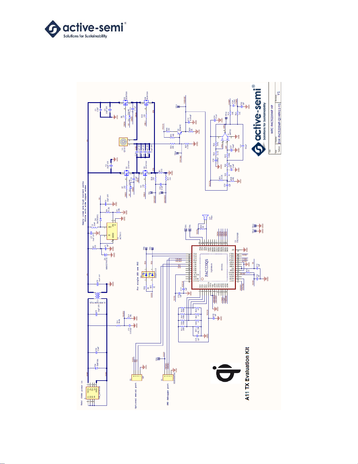
HIGH-PERFORMANCE (HP) SCHEMATIC

PAC5220WP A11 WPC
Transmitter Power Application Controller
© 2014 Copyright, Active-Semi International, Inc. - 11 - Rev 1.7 May, 2014
No portion of this document may be reproduced or reused in any form without Active-Semi’s prior written consent
HIGH-PERFORMANCE (LC) SCHEMATIC

PAC5220WP A11 WPC
Transmitter Power Application Controller
© 2014 Copyright, Active-Semi International, Inc. - 12 - Rev 1.7 May, 2014
No portion of this document may be reproduced or reused in any form without Active-Semi’s prior written consent
BILL OF MATERIALS (HP)
Quantity Designator Description Manufacturer MFG Part Number DK Part Number
3 C1, C28, C36 0603 Capacitor Kemet C0603C222J5RACTU 399-7879-1-ND
6 C2, C3, C4, C6, C7, C8 1206 X5R 20% Capacitor Taiyo Yuden LMK316BJ106KL-T 587-1342-1-ND
9
C5, C13, C15, C16, C17, C19,
C20, C26, C33
0603 Capacitor Kemet C0603C105K4RACTU 399-7847-1-ND
4 C9, C12, C14, C18 1206 C0G 5% Capacitor TDK C3216C0G1H104J160AA 445-7694-1-ND
4 C10, C11, C25, C29 0603 Capacitor Kemet C0603C104K4RACTU 399-1096-1-ND
1 C22 0603 Capacitor Kemet C0603C153J3GACTU 399-7904-1-ND
1 C23 0603 Capacitor Kemet C0603C821J5GACTU 399-3291-1-ND
1 C24 0603 Capacitor Kemet C0603C682J5RACTU 399-9121-1-ND
1 C27 0603 Capacitor Kemet C0603C562J5RACTU 399-7942-1-ND
1 C30 0603 Capacitor Kemet C0603C683J5RACTU 399-9121-1-ND
1 C31 0603 Capacitor Kemet C0603C333J5RACTU 399-9069-1-ND
1D1 Zener diode On Semi MM5Z5V6T1G MM5Z5V6T1GOSCT-ND
1D2 BAT43XV2 diode Fairchild BAT43 BAT43XV2TR-ND
2 D3, D5 1N4148 SOD523 diode Fairchild 1N4148WT 1N4148WTCT-ND
1D4 SOD123 TVS diode Littlefuse SMF18A F5820CT-ND
1D6 Surface Mount Chip LED (Red/Green) Avago HSMF-C155 516-1456-1-ND
1J1 Micro USB connector FCI 10104111-0001LF 609-4053-1-ND
1L1 Common mode inductor Murata DLW5BTM501TQ2L (Mouser) 81-DLW5BTM501TQ2L
1L2 1210 Inductor Taiyo Yuden CBC2518T220M 587-1616-2-ND
1L3 WPC TX coil TDK WT-505060-10K2-A11-G 445-9304-ND
1 LS1 Piezo buzzer Active-Semi CMT-1102-SMT 102-1264-1-ND
1P1 SMT RA header Sullins GEC04SBSN-M89 S1113E-04-ND
13
P2, TP1, TP2, TP3, TP4, TP5, TP6,
TP9, TP10, TP11, TP12, TP13, TP14
SMT RA header, Test point (pad only) NP NP NP
4 Q1, Q2, Q3, Q4 N-Channel DFN3x3 MOSFET Alpha Omega AON7200 785-1374-1-ND
1Q5 NPN SOT23 BJT NXP BC847C,215 568-1636-1-ND
1R1 1206 Current Sense Resistor Ohmite MCS1632R020FER MCS1632R020FERCT-ND
5 R3, R16, R21, R28, R32 0603 Resistor Yaego RC0603FR-0710KL 311-10.0KHRCT-ND
1R4 0603 Resistor Yaego RC0603FR-0741K2L 311-41.2KHRCT-ND
3 R5, R17, R18 0603 Resistor Yaego RC0603FR-07330RL 311-330HRCT-ND
4 R7, R8, R9, R10 0603 Resistor Yaego RC0603FR-07150RL 311-150HRCT-ND
1 R11 0603 Resistor Yaego RC0603FR-0715RL 311-15.0HRCT-ND
2 R13, R33 0603 Resistor Yaego RC0603FR-0720KL 311-20.0KHRCT-ND
1 R14 0603 Resistor Yaego RC0603FR-0786K6L 311-86.6KHRCT-ND
1 R15 0603 Resistor Yaego RC0603FR-0730KL 311-30.0KHRCT-ND
2 R19, R20 0603 Resistor Yaego RC0603FR-075K49L 311-5.49KHRCT-ND
1 R22 0603 Resistor Yaego RC0603FR-07107KL 311-107KHRCT-ND
4 R23, R30, R34, R37 0603 Resistor Yaego RC0603FR-071KL 311-1.00KHRCT-ND
1 R24 0603 Resistor Yaego RC0603FR-0712K1L 311-12.1KHRCT-ND
1 R27 0603 Resistor Yaego RC0603FR-073K01L 311-3.01KHRCT-ND
1 R29 0603 Resistor Yaego RC0603FR-072KL 311-2.00KHRCT-ND
1 R31 0603 Resistor Yaego RC0603FR-0716K2L 311-16.2KHRCT-ND
1 R36 0603 Resistor Yaego RC0603JR-07100RL 311-100GRCT-ND
3 R38, R40, R42 0603 Resistor Yaego RC0603FR-07100KL 311-100KHRCT-ND
3 R39, R41, R43 0603 Resistor Yaego RC0603JR-070RL 311-0.0GRCT-ND
1 RT1 0805 Thermistor BC Vishay NTCS0805E3103JMT BC2292CT-ND
1U1 ACT6311 Active-Semi ACT6311UC-T NA
1U2 PAC5220 Active-Semi PAC5220QS NA
1U3 SOT23 Opamp Fairchild LMV321AS5X LMV321AS5XCT-ND

PAC5220WP A11 WPC
Transmitter Power Application Controller
© 2014 Copyright, Active-Semi International, Inc. - 13 - Rev 1.7 May, 2014
No portion of this document may be reproduced or reused in any form without Active-Semi’s prior written consent
BILL OF MATERIALS (LC)
Quantity Designator Description Manufacturer MFG Part Number DK Part Number
3 C1, C28, C36 0603 Capacitor Kemet C0603C222J5RACTU 399-7879-1-ND
6 C2, C3, C4, C6, C7, C8 1206 X5R 20% Capacitor Taiyo Yuden LMK316BJ106KL-T 587-1342-1-ND
9
C5, C13, C15, C16, C17,
C19, C20, C26, C33
0603 Capacitor Kemet C0603C105K4RACTU 399-7847-1-ND
4 C9, C12, C14, C18 1206 C0G 5% Capacitor TDK C3216C0G1H104J160AA 445-7694-1-ND
4 C10, C11, C25, C29 0603 Capacitor Kemet C0603C104K4RACTU 399-1096-1-ND
1 C22 0603 Capacitor Kemet C0603C153J3GACTU 399-7904-1-ND
1 C23 0603 Capacitor Kemet C0603C821J5GACTU 399-3291-1-ND
1 C24 0603 Capacitor Kemet C0603C682J5RACTU 399-9121-1-ND
1 C27 0603 Capacitor Kemet C0603C562J5RACTU 399-7942-1-ND
1 C30 0603 Capacitor Kemet C0603C683J5RACTU 399-9121-1-ND
1 C31 0603 Capacitor Kemet C0603C333J5RACTU 399-9069-1-ND
1D1 Zener diode On Semi MM5Z5V6T1G MM5Z5V6T1GOSCT-ND
1D2 BAT43XV2 diode Fairchild BAT43 BAT43XV2TR-ND
2 D3, D5 1N4148 SOD523 diode Fairchild 1N4148WT 1N4148WTCT-ND
1D4 SOD123 TVS diode Littlefuse SMF18A F5820CT-ND
1D6 Surface Mount Chip LED (Red/Green) Avago HSMF-C155 516-1456-1-ND
1J1 Micro USB connector FCI 10104111-0001LF 609-4053-1-ND
1L2 1210 Inductor Taiyo Yuden CBC2518T220M 587-1616-2-ND
1L3 WPC TX coil TDK WT-505060-10K2-A11-G 445-9304-ND
1P1 SMT RA header Sullins GEC04SBSN-M89 S1113E-04-ND
12
P2, TP1, TP2, TP3, TP4, TP6,
TP9, TP10, TP11, TP12, TP13,
TP14
SMT RA header, Test point (pad only) NP NP NP
4 Q1, Q2, Q3, Q4 N-Channel DFN3x3 MOSFET Alpha Omega AON7410 785-1374-1-ND
1Q5 NPN SOT23 BJT NXP BC847C,215 568-1636-1-ND
1R1 1206 Current Sense Resistor Ohmite MCS1632R020FER MCS1632R020FERCT-ND
5 R3, R16, R21, R28, R32 0603 Resistor Yaego RC0603FR-0710KL 311-10.0KHRCT-ND
1R4 0603 Resistor Yaego RC0603FR-0741K2L 311-41.2KHRCT-ND
3 R5, R17, R18 0603 Resistor Yaego RC0603FR-07330RL 311-330HRCT-ND
4 R7, R8, R9, R10 0603 Resistor Yaego RC0603FR-07150RL 311-150HRCT-ND
1 R11 0603 Resistor Yaego RC0603FR-0715RL 311-15.0HRCT-ND
2 R13, R33 0603 Resistor Yaego RC0603FR-0720KL 311-20.0KHRCT-ND
1 R14 0603 Resistor Yaego RC0603FR-0786K6L 311-86.6KHRCT-ND
1 R15 0603 Resistor Yaego RC0603FR-0730KL 311-30.0KHRCT-ND
2 R19, R20 0603 Resistor Yaego RC0603FR-075K49L 311-5.49KHRCT-ND
1 R22 0603 Resistor Yaego RC0603FR-07107KL 311-107KHRCT-ND
3 R23, R34, R37 0603 Resistor Yaego RC0603FR-071KL 311-1.00KHRCT-ND
1 R24 0603 Resistor Yaego RC0603FR-0712K1L 311-12.1KHRCT-ND
1 R27 0603 Resistor Yaego RC0603FR-073K01L 311-3.01KHRCT-ND
1 R29 0603 Resistor Yaego RC0603FR-072KL 311-2.00KHRCT-ND
1 R31 0603 Resistor Yaego RC0603FR-0716K2L 311-16.2KHRCT-ND
1 R36 0603 Resistor Yaego RC0603JR-07100RL 311-100GRCT-ND
3 R38, R40, R42 0603 Resistor Yaego RC0603FR-07100KL 311-100KHRCT-ND
3 R39, R41, R43 0603 Resistor Yaego RC0603JR-070RL 311-0.0GRCT-ND
2 RJ1, RJ2 1206 0 ohm jumper Yageo RC1206JR-070RL 311-0.0ERCT-ND
1 RT1 0805 Thermistor BC Vishay NTCS0805E3103JMT BC2292CT-ND
1U1 ACT6311 Active-Semi ACT6311UC-T NA
1U2 PAC5220 Active-Semi PAC5220QS NA
1U3 SOT23 Opamp Fairchild LMV321AS5X LMV321AS5XCT-ND

PAC5220WP A11 WPC
Transmitter Power Application Controller
© 2014 Copyright, Active-Semi International, Inc. - 14 - Rev 1.7 May, 2014
No portion of this document may be reproduced or reused in any form without Active-Semi’s prior written consent
SIGNAL AND TEST POINT DESCRIPTIONS
Test Points
The following table shows the test point description for this EVK.
Test Point
Signal Name
Description
TP1
ISENSE-N
Current sense differential signals - negative input.
TP2
ISENSE-P
Current sense differential signals –positive input.
TP3
LED (D6)
PAC5220WP red LED output (active-low).
TP4
LED (D6)
PAC5220WP green LED output (active-low).
TP5
PAC5220WP PD4
Selects PCB configuration (HP/LC):
HP: Leave floating
LC: Must tie to ground
TP6
PAC5220WP PD5
PAC5220WP resistor configuration enable input. To enable resistor
configuration, leave floating or pull to ground. To disable this feature,
pull to 3.3V.
TP9
VSYS
PAC5220WP VSYS
TP10
OPO
Vpeak amplifier output (for receiver communications)
TP11
GND
Ground
TP12
VSENSE
Analog ping voltage input
TP13
GND
Ground
TP14
VPCOM
Unused
Header Descriptions
The following table shows the header descriptions for this EVK.
Header
Pin
Description
P1
1
PAC5220WP firmware update serial port ground.
2
PAC5220WP firmware update serial port clock.
3
PAC5220WP firmware update serial port data input/output.
4
PAC5220WP firmware update serial port power (5V).
P2
1
PAC5220WP host communication serial port power (5V).
2
PAC5220WP host communication serial port transmit.
3
PAC5220WP host communication serial port receive.
4
PAC5220WP host communication serial port ground.
Signal Descriptions
The following table shows the signal descriptions for the PAC5220WP for this application.
Signal
Sig#
PAC5220WP
Signal
Name
EVK
Function
Description
1
PC5
TEMP
NTC Thermistor input for coil temperature measurement.

PAC5220WP A11 WPC
Transmitter Power Application Controller
© 2014 Copyright, Active-Semi International, Inc. - 15 - Rev 1.7 May, 2014
No portion of this document may be reproduced or reused in any form without Active-Semi’s prior written consent
2
PC4
FODCFG
Analog input used for FOD threshold configuration, if RCFGEN
is low.
3
PC3
DTCFG
Analog input used for dead-time configuration, if RCFGEN is
low.
4
PC2
LEDCFG
Analog input used for LED configuration, if RCFGEN is low.
5
VCC33
Internally generated 3.3V power supply. Connect a 1μF or
higher value ceramic capacitor from VCC33 to VSSA.
6
VSSA
Analog ground. Connect to VSS in a star configuration.
7
VSS
Ground
8
AIO0
ISENSEN
Differential coil current sense negative input.
9
AIO1
ISENSEP
Differential coil current sense positive input.
10
AIO2
Unused
11
AIO3
Unused
12
AIO4
COMN
Differential voltage communication negative input.
13
AIO5
COMP
Differential voltage communication positive input.
14
AIO6
VSENSE
Analog ping voltage input.
15
AIO7
VBSEN
5V Voltage Input
16
AIO8
VPCOM
Unused
17
AIO9
Unused
18
VSYS
5V system power supply. Connect a 1μF or higher value
ceramic capacitor from VSYS to VSSP.
19
REGO
System regulator output. Connect to VSYS directly or through
an external power dissipating resistor.
20
CSM
Switching supply current sense input. Connect to the positive
side of the current sense resistor.
21
VP
Main power supply. Provides power to the power drivers as
well as voltage feedback path for the switching supply. Connect
a properly sized supply bypass capacitor in parallel with a
0.1μF ceramic capacitor from VP pin to VSS for voltage loop
stabilization. This pin requires good capacitive bypassing to
VSS, so the ceramic capacitor must be connected with a
shorter than 10mm trace from the pin.
22
VHM
Switching supply controller supply input. Connect a 1μF or
higher value ceramic capacitor, or a 0.1μF ceramic capacitor in
parallel with a 10μF or higher electrolytic capacitor from VHM
to VSSP. This pin requires good capacitive bypassing to VSSP,
so the ceramic capacitor must be connected with a shorter than
10mm trace from the pin.
23
DRM
Switching supply driver output. Connect to the base or gate of
the external power NPN or n-channel MOSFET. See
PAC51xx/52xx User Guide and application notes.
24
VSSP
Power ground. Connect to VSS in a star ground configuration.
25
DRL0
DRL0
Full-bridge low-side gate driver 1.
26
DRL1
DRL1
Full-bridge low-side gate driver 2.
27
DRL2
Unused
28
DRS3
DRS3
Full-bridge high-side gate driver source 1.
29
DRH3
DRH3
Full-bridge high-side gate driver 1.
30
DHB3
DRB3
Full-bridge high-side bootstrap 1.
31
DRS4
DRS4
Full-bridge high-side gate driver source 2.
32
DRH4
DRH4
Full-bridge high-side gate driver 2.
33
DRB4
DRB4
Full-bridge high-side bootstrap 2.

PAC5220WP A11 WPC
Transmitter Power Application Controller
© 2014 Copyright, Active-Semi International, Inc. - 16 - Rev 1.7 May, 2014
No portion of this document may be reproduced or reused in any form without Active-Semi’s prior written consent
34
DRS5
Unused
35
DRH5
Unused
36
DRZB5
Unused
37
OHI6
Unused
38
OHI7
Unused
39
PD7
PD7
Piezoelectric buzzer PWM output. Leave floating if no buzzer is
used.
40
PD6
Unused –leave floating.
41
PD5
TP6/RCFGEN
To enable resistor configuration, leave floating or pull to
ground. To disable this feature, pull to 3.3V.
42
PD4
TP5
Selects PCB configuration (HP/LC):
HP: Leave floating
LC: Must tie to ground
43
PD3
TP4
Dual-color LED enable (green, active-low).
44
PD2
TP3
Dual-color LED enable (red, active-low).
45
PD1
SWDCL
Factory use
46
PD0
SWDIO
Factory use
47
PE0
Unused –leave floating.
48
PE1
TX
Factory use
49
PE2
RX
Factory use
50
PE3
Unused –leave floating.
51
PE4
Unused –leave floating.
52
PE5
Unused –leave floating.
53
VCCIO
VCCIO
Internally generated digital I/O power supply. Connect a 4.7μF
or higher value ceramic capacitor from VCCIO to VSSA.
54
XIN
Crystal oscillator driver input. Leave floating.
55
XOUT
Crystal oscillator driver output. Leave floating.
56
VCC18
Internally generated 1.8V core power supply. Connect a 1μF
together with a 0.1μ. For higher value ceramic capacitor from
VCC18 to VSSA.
57
EP
Exposed pad. Must be connected to VSS in a star ground
configuration. Connect to a large PCB copper area for power
dissipation heat sinking.

PAC5220WP A11 WPC
Transmitter Power Application Controller
© 2014 Copyright, Active-Semi International, Inc. - 17 - Rev 1.7 May, 2014
No portion of this document may be reproduced or reused in any form without Active-Semi’s prior written consent
EVK SETUP
Connect the 5V power source via a micro-USB cable from the power supply to the EVK. Be sure to use at
least a 10W power supply, to be able to supply any WPC compliant receiver.
After a few seconds, the EVK is ready to use. The LED will remain off while the EVK is searching for valid
receivers. When a valid WPC receiver is placed on the charge pad and power transfer begins, the LED
turns green. Whenever the green LED is on, the receiver is being charged. The LED behavior is
configurable.
1
The receiver may be removed at any time and charging will stop within a few seconds.
1
For information on how to configure the LED, dead-time and FOD thresholds see the section on resistor
configuration later in this guide.

PAC5220WP A11 WPC
Transmitter Power Application Controller
© 2014 Copyright, Active-Semi International, Inc. - 18 - Rev 1.7 May, 2014
No portion of this document may be reproduced or reused in any form without Active-Semi’s prior written consent
FEATURE DESCRIPTION
Foreign Object Detection
The PAC5220WP implements the WPC’s Foreign Object Detection (FOD) according to the low-power
specification, version 1.1.
The PAC5220WP has four levels of foreign object detection using temperature, current, voltage and
communication disruptions to determine if a foreign object is on or near the charge pad. If a foreign object
is detected, then the EVK’s red LED will be illuminated. The device then waits for the receiver to be
removed from the charge pad, and then will delay for 30 seconds before resetting the state machine. At
that time, the state machine will return to the selection phase.
Power Limited Operation
The PAC5220WP EVK implements the WPC low-power transmitter specification. This specifies operation
for up to 5W receivers.
If a power supply is used that cannot deliver enough power for the receiver, then the PAC5220WP will
deliver as much power as it can, without affecting operation of the device and EVK.
When the PAC5220WP detects this condition (not enough supply power), the system will stay in this
power limiting mode and the LED is illuminated orange for the duration of the time that the receiver is
charging.
2
When the input voltage sensed is less than 4.6V, the system is put into this mode.
When the receiver is removed and re-placed on the charge pad, the WPC state machine starts over and
this condition is cleared and the EVK will attempt to deliver full power.
Thermal Protection
The PAC5220WP EVK periodically checks the temperature of the coil using an NTC thermistor.
If this temperature is ever greater than 45C, then the power transfer is stopped, the green and red LEDs
will be turned on. Operation will resume and the LED will be turned off when both the coil temperature
has fallen below 40C and 5 minutes has elapsed.
Over-Current Protection
The PAC5220WP EVK contains over-current protection for this application. This scenario is abnormal,
and implies a hardware failure.
If the coil current is ever more than 10A, then power transfer is stopped, and the red LED is illuminated
and the system is latched off until the EVK is reset.
2
This is the default behavior and can be changed via configuration.

PAC5220WP A11 WPC
Transmitter Power Application Controller
© 2014 Copyright, Active-Semi International, Inc. - 19 - Rev 1.7 May, 2014
No portion of this document may be reproduced or reused in any form without Active-Semi’s prior written consent
Over-Voltage Protection
The PAC5220WP EVK contains over-voltage protection for this application. If Vin is detected to be more
than the threshold (6.5V), then charging stops and will not re-start until Vin drops below this threshold.
The recovery for this condition is immediately after Vin drops below the threshold.

PAC5220WP A11 WPC
Transmitter Power Application Controller
© 2014 Copyright, Active-Semi International, Inc. - 20 - Rev 1.7 May, 2014
No portion of this document may be reproduced or reused in any form without Active-Semi’s prior written consent
LED Indications
The table below shows the default state of the dual-color LED for various operating conditions of the
PAC5220WP EVK.
3
Condition
LED
(green)
LED
(red)
Recovery
Searching for receiver/Idle
(WPC selection state)
Off
Off
n/a
Power Transfer
On
Off
n/a
Power Limited Operation
On
On
Remove receiver from charge pad.
Over-Voltage
Off
Off
Removes power and waits until voltage drops below
threshold before charging receiver. LEDs revert to
idle state (off by default).
Over-Temperature
Off
On
Both temperature drops below over-temperature
hysteresis value and 5 minutes elapse.
FOD detected
Off
On
Wait for removal of receiver and immediately reset,
or wait 15 seconds and reset –whichever comes
first.
Over-current on ISENSE
Off
On
Latch off
End Power Transfer:
Charge Complete, Battery
Failure or Internal Fault
On
On
Reset state machine after 5 seconds.
End Power Transfer: No
response
On
On
Wait for removal of receiver from charge pad and
immediately reset.
End Power Transfer:
Reconfigure
On
Off
n/a (charging does not stop)
End Power Transfer: any
other type (except
Reconfigure)
On
On
Reset state machine after 2 seconds.
Note that for certain End Power Transfer message types (charge complete and reconfigure), if three of
these messages are received in a row, then the PAC5220WP will terminate charge and wait until the
device has been removed from the charge pad before resuming charging (as specified in the Low-Power
specification).
3
Note that the LED behavior of this application is customer configurable.
Table of contents
Popular Transmitter manuals by other brands


Newham London
Newham London Roger Touchscreen Mic user guide and troubleshooter

Lattice
Lattice CSI2 to Parallel Bridge Board user guide

CMOSTEK
CMOSTEK NextGenRF CMT2189B User guideline

Bosch
Bosch CRS-NC-S37E-ACC operating instructions

Interphone
Interphone BTSplitter35 instruction manual

Rain Bird
Rain Bird TBOS-II Quick reference guide