WIKA DPT-20 User manual

Operating Instructions
Dierential pressure transmitter DPT-20
Foundation Fieldbus
Metallic measuring cell

2
Contents
WIKA Operating Instructions - Dierential pressure transmitter DPT-20
Contents
1 About this document ............................................................................................................... 4
1.1 Function ........................................................................................................................... 4
1.2 Target group ..................................................................................................................... 4
1.3 Symbols used................................................................................................................... 4
2 For your safety ......................................................................................................................... 5
2.1 Authorised personnel ....................................................................................................... 5
2.2 Appropriate use................................................................................................................ 5
2.3 Warning about incorrect use............................................................................................. 5
2.4 General safety instructions............................................................................................... 5
2.5 EU conformity................................................................................................................... 5
2.6 NAMUR recommendations .............................................................................................. 6
2.7 Installation and operation in the USA and Canada ........................................................... 6
3 Product description................................................................................................................. 7
3.1 Conguration.................................................................................................................... 7
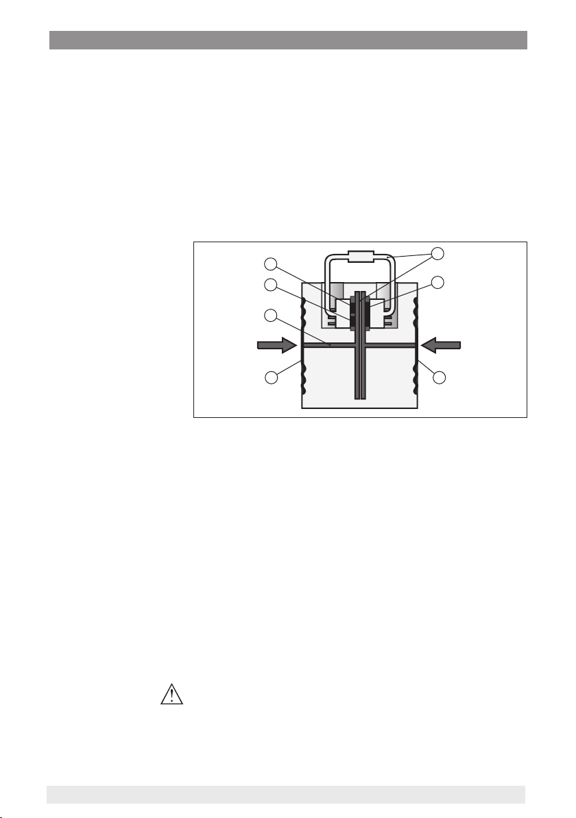
3.2 Principle of operation........................................................................................................ 8
3.3 Supplementary cleaning procedures.............................................................................. 10
3.4 Packaging, transport and storage................................................................................... 11
3.5 Accessories.................................................................................................................... 11
4 Mounting................................................................................................................................. 13
4.1 General instructions ....................................................................................................... 13
4.2 Instructions for oxygen applications ............................................................................... 15
4.3 Connection to the process.............................................................................................. 15
4.4 Mounting and connection instructions............................................................................ 16
4.5 Measurement setups...................................................................................................... 18
5 Connecting to the bus system.............................................................................................. 27
5.1 Preparing the connection ............................................................................................... 27
5.2 Connecting..................................................................................................................... 28
5.3 Wiring plans ................................................................................................................... 29
5.4 Switch-on phase............................................................................................................. 33
6 Set up the sensor with the display and adjustment module............................................. 34
6.1 Insert display and adjustment module............................................................................ 34
6.2 Adjustment system......................................................................................................... 35
6.3 Measured value indication.............................................................................................. 36
6.4 Parameter adjustment - Quick setup .............................................................................. 37
6.5 Parameter adjustment - Extended adjustment................................................................ 37
6.6 Saving the parameterisation data................................................................................... 51
7 Set up measuring system ..................................................................................................... 53
7.1 Level measurement........................................................................................................ 53
7.2 Flow measurement......................................................................................................... 55
8 Diagnosis, asset management and service ........................................................................ 57
8.1 Maintenance .................................................................................................................. 57
8.2 Diagnosis memory ......................................................................................................... 57
8.3 Asset Management function........................................................................................... 58
8.4 Rectify faults................................................................................................................... 60
8.5 Replace process anges................................................................................................ 61

3
Contents
WIKA Operating Instructions - Dierential pressure transmitter DPT-20
8.6 Exchange process module on version IP68 (25 bar) ...................................................... 62
8.7 Instrument repair ............................................................................................................ 63
9 Dismount................................................................................................................................. 64
9.1 Dismounting steps.......................................................................................................... 64
9.2 Disposal ......................................................................................................................... 64
10 Supplement ............................................................................................................................ 65
10.1 Technical data ................................................................................................................ 65
10.2 Device communication Foundation Fieldbus.................................................................. 76
10.3 Calculation of the total deviation..................................................................................... 77
10.4 Calculation of the total deviation - Practical example...................................................... 78
10.5 Dimensions, versions process component..................................................................... 79
10.6 Trademark ...................................................................................................................... 85
Safety instructions for Ex areas
Take note of the Ex specic safety instructions for Ex applications.
These instructions are attached as documents to each instrument
with Ex approval and are part of the operating instructions.
Editing status: 2021-01-11

4
1 About this document
WIKA Operating Instructions - Dierential pressure transmitter DPT-20
1 About this document
1.1 Function
This instruction provides all the information you need for mounting,
connection and setup as well as important instructions for mainte-
nance, fault rectication, the exchange of parts and the safety of the
user. Please read this information before putting the instrument into
operation and keep this manual accessible in the immediate vicinity
of the device.
1.2 Target group
This operating instructions manual is directed to trained personnel.
The contents of this manual must be made available to the qualied
personnel and implemented.
1.3 Symbols used
Information, note, tip: This symbol indicates helpful additional infor-
mation and tips for successful work.
Note: This symbol indicates notes to prevent failures, malfunctions,
damage to devices or plants.
Caution: Non-observance of the information marked with this symbol
may result in personal injury.
Warning: Non-observance of the information marked with this symbol
may result in serious or fatal personal injury.
Danger: Non-observance of the information marked with this symbol
results in serious or fatal personal injury.
Ex applications
This symbol indicates special instructions for Ex applications.
• List
The dot set in front indicates a list with no implied sequence.
1 Sequence of actions
Numbers set in front indicate successive steps in a procedure.
Battery disposal
This symbol indicates special information about the disposal of bat-
teries and accumulators.

5
2 For your safety
WIKA Operating Instructions - Dierential pressure transmitter DPT-20
2 For your safety
2.1 Authorised personnel
All operations described in this documentation must be carried out
only by trained, qualied personnel authorised by the plant operator.
During work on and with the device, the required personal protective
equipment must always be worn.
2.2 Appropriate use
DPT-20 is an instrument for measurement of ow, level, dierential
pressure, density and interface.
You can nd detailed information about the area of application in
chapter " Product description".
Operational reliability is ensured only if the instrument is properly
used according to the specications in the operating instructions
manual as well as possible supplementary instructions.
2.3 Warning about incorrect use
Inappropriate or incorrect use of this product can give rise to applica-
tion-specic hazards, e.g. vessel overll through incorrect mounting
or adjustment. Damage to property and persons or environmental
contamination can result. Also, the protective characteristics of the
instrument can be impaired.
2.4 General safety instructions
This is a state-of-the-art instrument complying with all prevailing
regulations and directives. The instrument must only be operated in a
technically awless and reliable condition. The operator is responsi-
ble for the trouble-free operation of the instrument. When measuring
aggressive or corrosive media that can cause a dangerous situation
if the instrument malfunctions, the operator has to implement suitable
measures to make sure the instrument is functioning properly.
The safety instructions in this operating instructions manual, the na-
tional installation standards as well as the valid safety regulations and
accident prevention rules must be observed by the user.
For safety and warranty reasons, any invasive work on the device
beyond that described in the operating instructions manual may be
carried out only by personnel authorised by the manufacturer. Arbi-
trary conversions or modications are explicitly forbidden. For safety
reasons, only the accessory specied by the manufacturer must be
used.
To avoid any danger, the safety approval markings and safety tips on
the device must also be observed.
2.5 EU conformity
The device fulls the legal requirements of the applicable EU direc-
tives. By axing the CE marking, we conrm the conformity of the
instrument with these directives.

6
2 For your safety
WIKA Operating Instructions - Dierential pressure transmitter DPT-20
The EU conformity declaration can be found on our homepage.
2.6 NAMUR recommendations
NAMUR is the automation technology user association in the process
industry in Germany. The published NAMUR recommendations are
accepted as the standard in eld instrumentation.
The device fulls the requirements of the following NAMUR recom-
mendations:
• NE 21 – Electromagnetic compatibility of equipment
• NE 53 – Compatibility of eld devices and display/adjustment
components
• NE 107 – Self-monitoring and diagnosis of eld devices
For further information see www.namur.de.
2.7 Installation and operation in the USA and
Canada
This information is only valid for USA and Canada. Hence the follow-
ing text is only available in the English language.
Installations in the US shall comply with the relevant requirements of
the National Electrical Code (ANSI/NFPA 70).
Installations in Canada shall comply with the relevant requirements of
the Canadian Electrical Code.

7
3 Product description
WIKA Operating Instructions - Dierential pressure transmitter DPT-20
3 Product description
3.1 Conguration
The scope of delivery encompasses:
• Instrument DPT-20
The further scope of delivery encompasses:
• Documentation
– Quick setup guide DPT-20
– Test certicate for pressure transmitters
– Instructions for optional instrument features
– Ex-specic " Safety instructions" (with Ex versions)
– If necessary, further certicates
Information:
Optional instrument features are also described in this operating
instructions manual. The respective scope of delivery results from the
order specication.
This operating instructions manual applies to the following instrument
versions:
• Hardware from 1.0.0
• Software version from 1.2.1
Note:
You can nd the hardware and software version of the instrument as
follows:
• On the type plate of the electronics module
• In the adjustment menu under " Info"
The type label contains the most important data for identication and
use of the instrument:
1
6
7
9
8
2
3
4
5
Fig. 1: Layout of the type label (example)
1 Instrument type
2 Field for approvals
3 Technical data
4 Product code
5 Order number
6 Serial number of the instrument
7 Symbol of the device protection class
8 ID numbers, instrument documentation
9 Reminder to observe the instrument documentation
Scope of delivery
Scope of this operating
instructions
Type label

8
3 Product description
WIKA Operating Instructions - Dierential pressure transmitter DPT-20
3.2 Principle of operation
DPT-20 is suitable universally for applications in virtually all industries.
It is used for the measurement of the following pressure types:
• Dierential pressure
• Static pressure
Measured products are gases, vapours and liquids.
The dierential pressure measurement enables the measurement of:
• Level
• Flow
• Dierential pressure
• Density
• Interface
The instrument is suitable for level measurement in closed, superim-
posed pressure vessels. The static pressure is compensated by dier-
ential pressure measurement. It is available as a separate measured
value for digital signal outputs.
Fig. 2: Level measurement with DPT-20 in a pressurized vessel
The ow measurement is carried out via an eective pressure trans-
mitter, such as an orice plate or pitot tube. The device records the
resulting pressure dierence and converts the measured value into
the ow. With digital signal outputs, the static pressure is available as
a separate measured value.
Q
p1p2
+–
Fig. 3: Flow measurement with DPT-20 and orice, Q = ow, dierential pres-
sure Δp = p1- p2
Application area
Measured products
Measured variables
Level measurement
Flow measurement

9
3 Product description
WIKA Operating Instructions - Dierential pressure transmitter DPT-20
The pressures in two dierent pipelines are acquired via eective
pressure lines. The device determines the dierential pressure.
+
p12
p
Fig. 4: Measurement of the dierential pressure in pipelines with DPT-20, dif-
ferential pressure Δp = p1- p2
With the help of the instrument, density measurement in a vessel with
changing level and homogeneous density distribution can be easily
realized. The instrument is connected to the vessel via a chemical
seal at two dierent measuring points.
+
–
Fig. 5: Density measurement with DPT-20
The instrument can also be used for interface measurement in a ves-
sel with changing level. The instrument is connected to the vessel via
a chemical seal at two dierent measuring points.
+
–
Fig. 6: Interface measurement with DPT-20
Dierential pressure
measurement
Density measurement
Interface measurement

10
3 Product description
WIKA Operating Instructions - Dierential pressure transmitter DPT-20
A metallic measuring cell is used as sensor element. The process
pressures are transmitted via the separating diaphragms and lling
oils to a piezoresistive sensor element (resistance measuring bridge
using semiconductor technology).
The dierence between the acting pressures changes the bridge volt-
age. This change is measured, further processed and converted into
a corresponding output signal.
When measurement limits are exceeded, an overload system protects
the sensor element against damage.
In addition, the measuring cell temperature and the static pressure
are measured on the low pressure side. The measuring signals are
further processed and are available as additional output signals.
P P
5
4
66
3
2
1
Fig. 7: Conguration metallic measuring cell
1 Filling uid
2 Temperature sensor
3 Absolute pressure sensor, static pressure
4 Overload system
5 Dierential pressure sensor
6 Separating diaphragm
3.3 Supplementary cleaning procedures
The DPT-20 is also available in the version " Oil, grease and silicone-
free". These instruments have passed through a special cleaning
procedure to remove oil, grease and paint-wetting impairment sub-
stances (PWIS).
The cleaning is carried out on all wetted parts as well as on surfaces
accessible from outside. To keep the purity level, the instruments are
immediately packed in plastic foil after the cleaning process. The
purity level remains as long as the instrument is kept in the closed
original packaging.
Caution:
The DPT-20 in this version may not be used in oxygen applications.
For this purpose, instruments are available in the special version " Oil,
grease and silicone-free for oxygen applications".
Functional principle

11
3 Product description
WIKA Operating Instructions - Dierential pressure transmitter DPT-20
3.4 Packaging, transport and storage
Your instrument was protected by packaging during transport. Its
capacity to handle normal loads during transport is assured by a test
based on ISO 4180.
The packaging consists of environment-friendly, recyclable card-
board. For special versions, PE foam or PE foil is also used. Dispose
of the packaging material via specialised recycling companies.
Caution:
Instruments for oxygen applications are sealed in PE foil and provided
with a label "Oxygen! Use no Oil". Remove this foil just before mount-
ing the instrument! See instruction under " Mounting".
Transport must be carried out in due consideration of the notes on the
transport packaging. Nonobservance of these instructions can cause
damage to the device.
The delivery must be checked for completeness and possible transit
damage immediately at receipt. Ascertained transit damage or con-
cealed defects must be appropriately dealt with.
Up to the time of installation, the packages must be left closed and
stored according to the orientation and storage markings on the
outside.
Unless otherwise indicated, the packages must be stored only under
the following conditions:
• Not in the open
• Dry and dust free
• Not exposed to corrosive media
• Protected against solar radiation
• Avoiding mechanical shock and vibration
• Storage and transport temperature see chapter " Supplement -
Technical data - Ambient conditions"
• Relative humidity 20 … 85 %
With instrument weights of more than 18 kg (39.68 lbs) suitable and
approved equipment must be used for lifting and carrying.
3.5 Accessories
The display and adjustment module is used for measured value indi-
cation, adjustment and diagnosis.
DI-PT-E iis an external display and adjustment unit for sensors with
single chamber housing and Ex d double chamber housing.
The overvoltage arrester is used instead of the terminals in the single
or double chamber housing.
The suitable mounting accessories for DPT-20 include oval ange
adapters, valve blocks as well as mounting brackets.
Packaging
Transport
Transport inspection
Storage
Storage and transport
temperature
Lifting and carrying
Display and adjustment
module
External display and
adjustment unit
Overvoltage protection
Mounting accessories

12
3 Product description
WIKA Operating Instructions - Dierential pressure transmitter DPT-20

13
4 Mounting
WIKA Operating Instructions - Dierential pressure transmitter DPT-20
4 Mounting
4.1 General instructions
Note:
For safety reasons, the instrument must only be operated within the
permissible process conditions. You can nd detailed information on
the process conditions in chapter " Technical data" of the operating
instructions or on the type label.
Hence make sure before mounting that all parts of the instrument ex-
posed to the process are suitable for the existing process conditions.
These are mainly:
• Active measuring component
• Process tting
• Process seal
Process conditions in particular are:
• Process pressure
• Process temperature
• Chemical properties of the medium
• Abrasion and mechanical inuences
The permissible process pressure range is specied on the type label
with "MWP" (Maximum Working Pressure), see chapter " Congura-
tion". This specication refers to a reference temperature of +25 °C
(+76 °F). The MWP may also be permanently applied on one side.
In order to prevent damage to the device, a test pressure acting on
both sides may only exceed the specied MWP briey by 1.5 times
at reference temperature. The pressure stage of the process tting as
well as the overload resistance of the measuring cell are taken into
consideration here (see chapter " Technical Data").
In addition, a temperature derating of the process tting, e. g. with
ange isolating diaphragms, can limit the permissible process pres-
sure range according to the respective standard.
Protect your instrument against moisture ingress through the following
measures:
• Use a suitable connection cable (see chapter " Connecting to
power supply")
• Tighten the cable gland or plug connector
• Lead the connection cable downward in front of the cable entry or
plug connector
This applies mainly to outdoor installations, in areas where high
humidity is expected (e.g. through cleaning processes) and on cooled
or heated vessels.
Note:
Make sure that during installation or maintenance no moisture or dirt
can get inside the instrument.
Process conditions
Permissible process
pressure (MWP)
Protection against mois-
ture

14
4 Mounting
WIKA Operating Instructions - Dierential pressure transmitter DPT-20
To maintain the housing protection, make sure that the housing lid is
closed during operation and locked, if necessary.
The ventilation for the electronics housing is realised via a lter ele-
ment in the vicinity of the cable glands.
1 2 3
6
6
6 6
6
5
4
Fig. 8: Position of the lter element - non-Ex, Ex-ia and Ex-d-ia version
1 Plastic, stainless steel single chamber (precision casting)
2 Aluminium - single chamber
3 Stainless steel single chamber (electropolished)
4 Plastic double chamber
5 Aluminium, stainless steel double chamber housing (precision casting)
6 Filter element
Information:
Make sure that the lter element is always free of buildup during op-
eration. A high-pressure cleaner may not be used for cleaning.
For better readability of the display or access to the wiring, the elec-
tronics housing can be rotated by 330°. A stop prevents the housing
from being turned too far.
Depending on the version and housing material, the locking screw on
the neck of the housing must be slightly loosened. The housing can
then be turned to the correct position. As soon as the requested posi-
tion is reached, tighten the locking screw.
It is recommended to protect the device at the application site against
lateral forces, e.g. vibrations, by means of a suitable measuring instru-
ment holder. This applies especially for device versions with a plastic
process connection, e.g. with G½ thread.
If there is strong vibration at the mounting location, the instrument
version with external housing should be used. See chapter " External
housing".
Ventilation
Turning the housing
Mounting at the applica-
tion site

15
4 Mounting
WIKA Operating Instructions - Dierential pressure transmitter DPT-20
Higher process temperatures often mean also higher ambient
temperatures. Make sure that the upper temperature limits stated in
chapter " Technical data" for the environment of the electronics hous-
ing and connection cable are not exceeded.
4.2 Instructions for oxygen applications
Oxygen and other gases can be explosive when brought into contact
with oils, grease and plastics, so the following measures must also be
taken:
• All components of the system, e.g. measuring instruments, must
be cleaned in accordance with the requirements of recognized
regulations or standards
• Depending on the seal material, certain temperatures and pres-
sures must not be exceeded in oxygen applications, see chapter "
Technical data"
Danger:
Instruments for oxygen applications must be unpacked just before
mounting. After removing the protective cover of the process tting,
the label "O2" will be visible on the process tting. Penetration of oil,
grease and dirt should be avoided. Danger of explosion!
4.3 Connection to the process
DP ow elements are installations in pipelines which generate a
ow-dependent pressure drop. The ow rate is measured via this dif-
ferential pressure. Typical DP ow elements are Venturi tubes, orice
plates or impact pressure probes.
Instructions for mounting the DP ow elements are stated in the ap-
propriate standards as well as in the documentation from the respec-
tive manufacturer.
Eective pressure lines are pipelines with a small diameter. They are
used to connect the dierential pressure transmitter to the pressure
tapping point or the DP ow element.
Principles
Eective pressure lines for gases must always remain completely dry
and no condensate must collect. Eective pressure lines for liquids
must always be completely lled and must not contain any gas bub-
bles. Therefore, suitable venting systems must be provided for liquids
and suitable drainage systems for gases.
Wiring
Eective pressure lines must always run with a sucient, strictly mo-
notonous slope/gradient of at least 2 %, but better up to 10 %.
Recommendations for wiring of eective pressure lines are stated in
the corresponding national and international standards.
Connection
Eective pressure lines are connected to the device via standard cut-
ting ring screw connections with suitable thread.
Temperature limits
Oxygen applications
DP ow element
Eective pressure lines

16
4 Mounting
WIKA Operating Instructions - Dierential pressure transmitter DPT-20
Note:
Follow the mounting instructions of the respective manufacturer and
seal the thread, e.g. with PTFE tape.
Valve blocks are used for initial shut-o when connecting the dier-
ential pressure transmitter to the process. They are also used for pres-
sure compensation of the measuring chambers during adjustment.
3-fold and 5-fold valve blocks are available (see chapter " Mounting
and connection instructions").
Free openings on the process assembly must be closed by ventilation
valves or closing screws. Required torque see chapter " Technical
data".
Note:
Use the supplied parts and seal the thread with four layers of PTFE
tape.
4.4 Mounting and connection instructions
When connecting DPT-20 to the measuring point, take note of the
high/low pressure side of the process component. 1).
The " H" identies the high pressure side, the low pressure side due
to an " L" on the process component next to the oval anges.
Note:
The static pressure is measured on the low pressure side " L".
2
1
H L
Fig. 9: Marking for high/low pressure side on the process component
1 H = High pressure side
2 L = Low pressure side
Valve blocks
Ventilation valves, closing
screws
Connection high/low
pressure side
1) The pressure eective on "H" is considered as positive, the pressure eec-
tive on "L" as negative in the calculation of the pressure dierence.

17
4 Mounting
WIKA Operating Instructions - Dierential pressure transmitter DPT-20
A:
A
2 2
1
3 45
Fig. 10: Connection of a 3-fold valve block
1 Process tting
2 Process tting
3 Inlet valve
4 Inlet valve
5 Breather valve
A:
A
2 2
13 45
Fig. 11: Connection of a 3-fold valve block, anging on both sides
1 Process tting
2 Process tting
3 Inlet valve
4 Inlet valve
5 Breather valve
3-fold valve block
3-fold valve block, ang-
ing on both sides

18
4 Mounting
WIKA Operating Instructions - Dierential pressure transmitter DPT-20
Note:
No mounting bracket is required for valve blocks that can be ange-
mounted on both sides. The process side of the valve block is
mounted directly to a DP ow element, e.g. an orice plate.
A:
A
2 2
1
4
7
3 5
6
Fig. 12: Connection of a 5-fold valve block
1 Process tting
2 Process tting
3 Inlet valve
4 Breather valve
5 Inlet valve
6 Valve for checking/ventilating
7 Valve for checking/ventilating
4.5 Measurement setups
4.5.1 Overview
The following sections show common measurement setups:
• Level
• Flow
• Dierential pressure
• Interface
• Density
Depending on the application, there may also be dierent arrange-
ments.
Note:
For simplication, the eective pressure lines are partly shown with
a horizontal course and sharp angles. For wiring, please observe the
instructions in chapter " Mounting, Connection to the process" as well
5-fold valve block

19
4 Mounting
WIKA Operating Instructions - Dierential pressure transmitter DPT-20
as the hook ups in the supplementary instructions " Mounting acces-
sory pressure technology".
4.5.2 Level
• Mount device below the lower measurement connection so that
the eective pressure lines are always lled with liquid
• Always connect the low pressure side above the max. level in the
vessel
• For measurement in products with solid content, such as e.g. dirty
liquids, the installation of separators and drain valves is recom-
mended. Debris and sediment can thus be collected and removed.
+
–
min.
max.
1
3
4
3
4
5
2
1
Fig. 13: Measurement setup, level measurement in closed vessel
1 Blocking valves
2 3-fold valve block
3 Precipitator
4 Drain valves
5 DPT-20
• Mount device directly to the vessel
• Always connect the low pressure side above the max. level in the
vessel
• For measurement in products with solid content, such as e.g. dirty
liquids, the installation of separators and drain valves is recom-
mended. Debris and sediment can thus be collected and removed.
In closed vessels with ef-
fective pressure lines
In closed vessels with
single chemical seal

20
4 Mounting
WIKA Operating Instructions - Dierential pressure transmitter DPT-20
+
–
max.
min.
1
2
3
4
Fig. 14: Measurement setup, level measurement in closed vessel
1 Blocking valve
2 Precipitator
3 Drain valve
4 DPT-20
• Mount device below the lower chemical seal
• The ambient temperature should be the same for both capillaries
Information:
Level measurement is only carried out between the upper edge of the
lower and the lower edge of the upper chemical seal.
+
–
min.
max.
1
Fig. 15: Measurement setup, level measurement in closed vessel
1 DPT-20
• Mount device below the lower measurement connection so that
the eective pressure lines are always lled with liquid
• Always connect the low pressure side above the max. level in the
vessel
• The condensate vessel ensures a constant pressure on the low
pressure side
• For measurement in products with solid content, such as e.g. dirty
liquids, the installation of separators and drain valves is recom-
mended. Debris and sediment can thus be collected and removed.
In closed vessels with
double chemical seal
In closed vessels with
steam layering with eec-
tive pressure line
Table of contents
Other WIKA Transmitter manuals