ITALIANO - 1/5MI001381-I/E
MI001381-I/E MI001381-I/E
MI001381-I/E MI001381-I/E ITALIANO - 5/5
ITALIANO - 2/5
ITALIANO - 3/5
ITALIANO - 4/5
ITRASDUTTORE DI TENSIONE ALTERNATA
E CONTINUA Z202-LP
SPECIFICHE TECNICHE
CARATTERISTICHE GENERALI
Il modulo Z202-LP è un convertitore di tensione loop-powered che misura il valore della
tensione alternata (valor medio tarato sull’efficace) o continua applicata ai morsetti di
ingresso, convertendolo in un segnale normalizzato in corrente ai morsetti d'uscita. Lo
strumento si distingue per la classe di precisione, il consumo ridotto e l’ampia
configurabilità.
Le caratteristiche generali di cui gode sono le seguenti:
Ingresso in tensione fino a 500 Vac in 5 scale pretarate, selezionabili tramite DIP-switch.
Possibilità di estendere ogni scala a quella successiva, consentendo la calibrazione in
un qualsiasi punto intermedio del range continuo 0..500 Vac, senza né starare le portate
fisse, né aprire lo strumento (tramite trimmer multigiri accessibile dal frontalino).
Elevata classe di precisione: 0.3 (su fondo scala di 300 Vac).
Range esteso della frequenza d'ingresso per la tensione alternata (20 Hz..400 Hz).
Tempo di risposta estremamente breve (< 100 ms).
Isolamento galvanico tra porte di ingresso e uscita pari a 4000 Vac.
Ridotto ripple d’uscita ed elevata velocità di risposta alle variazioni dell’ingresso.
(1): L’errore massimo va aumentato di 20 µA per tensioni di ingresso inferiori a 10 Vac o per tensioni
continue.
(2): Le precisioni sono indicate per un segnale sinusoidale.
(3): L’acronimo “d.m.” sta per “della misura”
Il modulo è progettato per essere montato su guida DIN 46277 e cablato unicamente a
mezzo dei morsetti frontali. Al fine di favorire la ventilazione del modulo stesso, ne viene
consigliato il montaggio in posizione verticale, evitando di posizionare canaline o altri
oggetti che ne occludano le feritoie di aereazione.
Evitare di collocare il modulo sopra apparecchiature che generino calore; è consigliabile la
collocazione nella parte bassa del quadro o del vano di contenimento.
ATTENZIONE!
PRIMA DI MANOVRARE I DIP-SWITCH ACCERTARSI DI AVERE
DISCONNESSO TUTTI I CIRCUITI A TENSIONE PERICOLOSA.
Lo strumento soddisfa alle norme 60688/1997; in particolare, le prove di eccedenza di
breve durata delle grandezze in entrata sono riferite al valore nominale della tensione di
ingresso indicate in Altre Caratteristiche.
Sovraccarichi superiori alla tensione massima stabilita nelle Caratteristiche d’Ingresso
possono causare il danneggiamento.
La portata dello strumento è stabilita dall'impostazione dell’unico DIP-Switch a 4 vie; le
prime tre posizione (DIP 1..3) selezionano una delle 5 scale di base precalibrate, mentre il
quarto dip-switch (normalmente chiuso) abilita l’inserzione del trimmer a pannello, che
consente un’aggiunta alla scala di base di 0..100 Vac (0..90 Vdc) in regolazione continua:
ruotando il trimmer in senso orario aumenta l’uscita (si riduce il valore di fondo scala)
viceversa si riduce l’uscita aumentando il valore di fondo scala. Qualora sia applicata una
tensione all’ingresso, è obbligatorio fare uso di un cacciavite isolato, non essendo
garantito l’isolamento della vite di regolazione.
Il limite inferiore della tensione di ingresso è pari a 4 Vac o 5 Vdc per ogni portata. Questi
valori sono la soglia al di sotto della quale lo strumento rileva 0, ovvero trasmette 4 mA.
La tabella sottostante riporta le combinazioni utili per le portate pretarate.
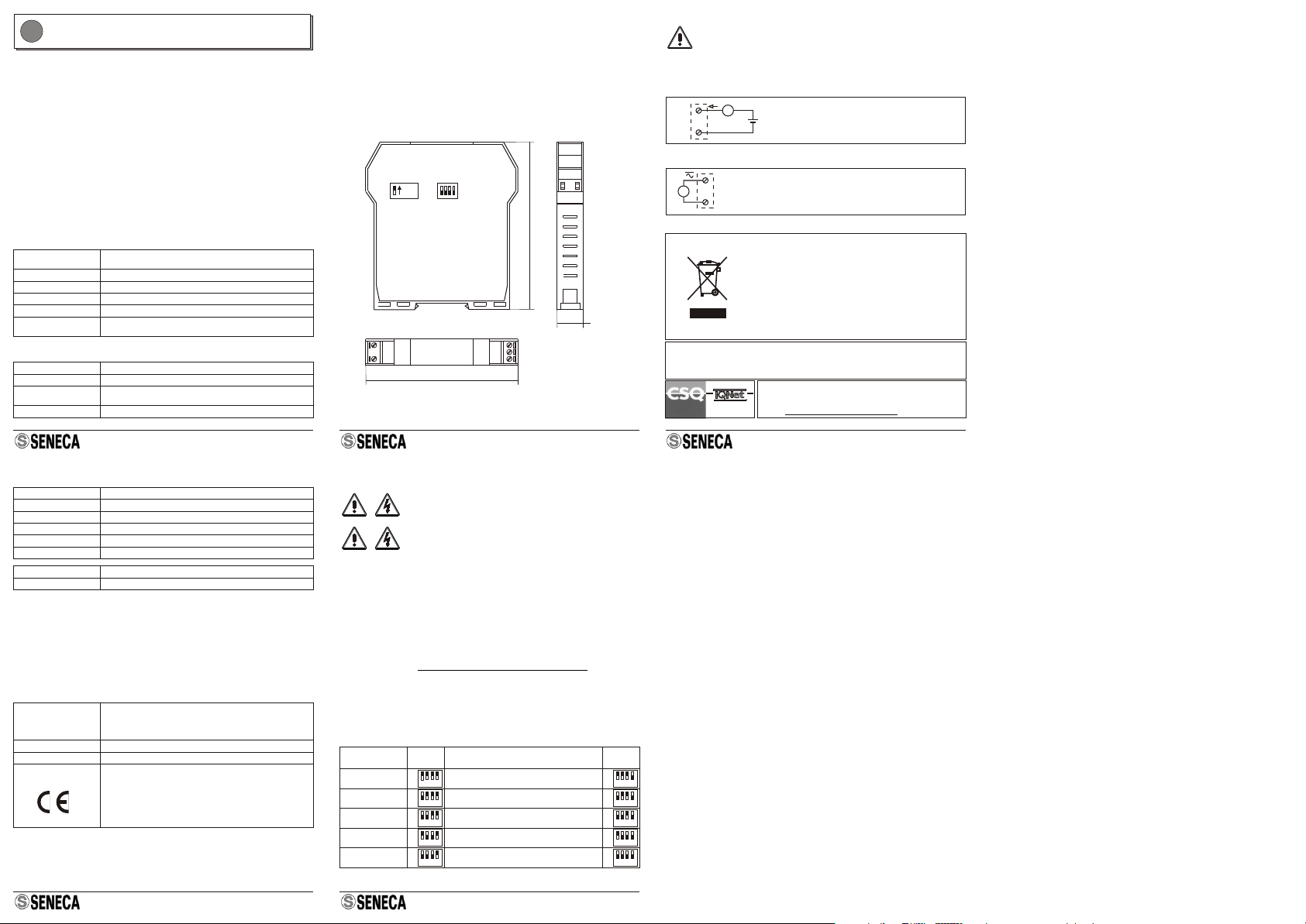
Collegamento Loop
NORME DI INSTALLAZIONE
Ingombri - Posizione DIP-Switch
IMPOSTAZIONE PORTATAINGRESSO
PORTATA : Vedi “IMPOSTAZIONE PORTATA INGRESSO”
V
12
10
SWITCH
SENECA s.r.l.
Via Germania, 34 - 35127 - Z.I. CAMIN - PADOVA- ITALY
Tel. +39.049.8705355 - 8705359 - Fax +39.049.8706287
THE INTERNATIONALCERTIFICATION NETWORK
R
ISO9001-2000
Smaltimento dei rifiuti elettrici ed elettronici (applicabile nell’Unione
Europea e negli altri paesi con servizio di raccolta differenziata).
Il simbolo presente sul prodotto o sulla sua confezione indica che il prodotto
non verrà trattato come rifiuto domestico. Sarà invece consegnato al centro di
raccolta autorizzato per il riciclo dei rifiuti elettrici ed elettronici. Assicurandovi
che il prodotto venga smaltito in modo adeguato, eviterete un potenziale
impatto negativo sull’ambiente e la salute umana, che potrebbe essere
causato da una gestione non conforme dello smaltimento del prodotto. Il
riciclaggio dei materiali contribuirà alla conservazione delle risorse naturali.
Per ricevere ulteriori informazioni più dettagliate Vi invitiamo a contattare
l’ufficio preposto nella Vostra città, il servizio per lo smaltimento dei rifiuti o il
fornitore da cui avete acquistato il prodotto.
Caratteristiche Ingresso
Caratteristiche Loop
(1)(2)
Caratteristiche Precisione
Altre Caratteristiche
Consumo: < 1mA per qualsiasi tensione di ingresso
Ingresso Tensione: Tensione alternata 0..500 Vac; tensione continua 0..540 Vdc;
si veda la tabella per la selezione della portata.
Frequenza: DC / 20 Hz .. 400 Hz
Isolamento: 4000 VAC
Categoria sovratensio-
ne di misura:
§CAT III fino a 300 Vac verso terra
§CAT II fino a 600 Vac verso terra
Caratteristiche generali: Passivo, 4..20 mA
Massima corrente: 35 mA in condizioni di overload.
Tensione di
alimentazione esterna: Da 5 a 28 Vdc.
Tempo di risposta: Per una variazione a gradino: < 100 ms dal 10 al 90 %.
Portata (3)
Errore di misura
100 Vac / 90 Vdc 0,3 % d.m. + 70 µA
200 Vac / 180 Vdc 0,3 % d.m. + 40 µA
300 Vac / 270 Vdc 0,2 % d.m. + 30 µA
400 Vac / 360 Vdc 0,3 % d.m. + 30 µA
500 Vac / 450 Vdc 0,3 % d.m. + 30 µA
Stabilità termica 150ppm / K
Errore EMI < 40 µA
Tensione Massima: 710 Vpk indipendente dalla portata selezionata
Condizioni ambientali:
Temperatura: -20..65°C, umidità 30..90 % @ 40°C non
condensante. Gruppo climatico III.
Temperatura di stoccaggio: -20..85 °C.
Altitudine: < 2000 m s.l.m.
Grado di protezione: IP20
Peso, Dimensioni: 140 g, 100 x 112 x 17.5 mm.
Normative di
Conformità
EN60688/1997 + A1 + A2.(Valore nominale di tensione
d’ingresso = 300 Vac)
EN61000-6-4/2002-10 (emissione elettromagnetica,
ambiente industriale).
EN61000-6-2/2006-10 (immunità elettromagnetica,
ambiente industriale).
EN61010-1/2001 (sicurezza).
112 mm
17,5 mm
100 mm
Portata Portata / TrimmerDIP
100Vac / 90 Vdc 100 Vac + 0..100 Vac / 90 Vdc + 0..90 Vdc
200Vac / 180 Vdc 200 Vac + 0..100 Vac / 180 Vdc + 0..90 Vdc
300Vac / 270 Vdc 300 Vac + 0..100 Vac / 270 Vdc + 0..90 Vdc
400Vac / 360 Vdc 400 Vac + 0..100 Vac / 360 Vdc + 0..90 Vdc
500Vac / 450 Vdc (1)
500 Vac + 0..100 Vac / 450 Vdc + 0..90 Vdc
DIP
1 2 34
1 2 34
1 2 34
1 2 34
1 2 34
1 2 34
1 2 34
1 2 34
1 2 34
1 2 34
1 2 34
on
off
on
off
on
off
on
off
on
off
on
off
on
off
on
off
on
off
on
off
3
1
mA
+
Vext
+
ext. supply
max 28 V
Collegamento Tensione in Ingresso
Questo documento è di proprietà SENECA srl. La duplicazione e la riproduzione sono vietate, se non
autorizzate. Il contenuto della presente documentazione corrisponde ai prodotti e alle tecnologie descritte. I
dati riportati potranno essere modificati o integrati per esigenze tecniche e/o commerciali. Il contenuto della
presente documentazione viene comunque sottoposto a revisione periodica.
(1): La tensione massima applicabile non deve comunque eccedere 500 Vac o 710 Vpk
ON
KEY
ATTENZIONE!
PRIMA DI EFFETTUARE QUALSIASI COLLEGAMENTO ALLO
STRUMENTO ACCERTARSI DI AVERE DISCONNESSO TUTTI I CIRCUITI
A TENSIONE PERICOLOSA.
COLLEGAMENTI ELETTRICI
ATTENZIONE!
PER REGOLARE IL TRIMMER A PANNELLO È OBBLIGATORIO
FARE USO DI UN CACCIAVITE ISOLATO.


