WIKA OBSOLETE DELTA-trans User manual

Operating Instructions
Betriebsanleitung
Mode d’emploi
GB
D
F
W
Differential Pressure Transmitter DELTA-trans
Model 891.34.2189
Differenzdruck-Messumformer DELTA-trans
Typ 891.34.2189
Transmetteur de pression différentielle DELTA-trans
Type 891.34.2189
DELTA-trans Model 891.34.2189 with integrated 3½-digit LCD-display
(optional) and compression fitting with ferrule (optional)

GB
D
F
Operating Instructions Differential Pressure Transmitter
DELTA-trans Model 891.34.2189 Page 3 - 15
Betriebsanleitung Differenzdruck-Messumformer
DELTA-trans Typ 891.34.2189 Seite 17 - 29
Mode d‘emploi Transmetteur de pression différentielle
DELTA-trans Type 891.34.2189 Page 31 - 43
2279453 08/2009 GB/D/F

GB
Contents
1. Safety instructions 4
2. Operating principle 4
3. Installation instructions 5
4. Installation and commissioning 6
5. Measuring arrangements 7
6. Wiring details 7
7. Version with LCD-display (optional extra) 8
8. Technical data 9
9. Service and maintenance 11
10. Special instructions for integrated pressure equalising valve
or 4-way valve manifold
12
11. Storage 14
12. Troubleshooting 14
13. Maintenance and servicing 15
14. Repairs 15
15. Disposal 15
2279453 08/2009 GB/D/F
WIKA Operating Instructions Differential Pressure Transmitter DELTA-trans 3
Contents
Warning!
This symbol warns you against actions that can cause
injury to people or damage to the instrument.

GB
1. Safety instructions / 2. Operating principle
2155079.01
2279453 08/2009 GB/D/F
WIKA Operating Instructions Differential Pressure Transmitter DELTA-trans4
1. Safety instructions
The appropriate national safety regulations (i.e. VDE 0100 /
EN 60 079-14 / EN 837-2) must be observed when installing,
commissioning and operating these instruments.
Do not work on the gauge while it is powered
Serious injuries and/or damage can occur should the appropriate regulations
not be observed
Only appropriately qualified personnel should work on these instruments
2. Operating principle
The differential pressure transmitter consists mainly of a mechanical measu-
ring system (1) with an elastic pressure element (2), a Hall-effect sensor (3) with
signal processing board (4) and a case with the connections for the electronics.
A magnet (5), rigidly coupled to the
pressure element, influences the
electromagnetic field of the HALL-
effect sensor. The resulting signal is
amplified to a standard output signal
via the signal processing board.
For recalibration, zero and span
can be adjusted by means of easily
accessible potentiometers (6).
Pressure entries are identified by the
symbols; j high pressure and i low
pressure

GB
3. Installation instructions
2279453 08/2009 GB/D/F
WIKA Operating Instructions Differential Pressure Transmitter DELTA-trans 5
3. Installation instructions
Installation arrangement
The pressure transmitter should be installed and operated without exposure
to vibration. It is common practise to install the pressure transmitter fitted to
an isolating device to enable replacement while the system is pressurised
and to isolate the transmitter when reading is not required.
Test connector
Local safety codes such as those for pressure or steam vessels may specify
isolating devices to enable on-site testing of the pressure transmitter.
Mounting provisions
If the pressure system or tailpipe is not rigid enough to accept the weight of
the transmitter, or capable of withstanding any vibrations present, the trans-
mitter should be wall-mounted using a suitable bracket.
Effects of temperature
The operating temperature of the pressure transmitter, resulting from the
effects of the pressure medium, ambient temperatures and possible radiated
heat, must not exceed the temperature range the pressure transmitter is
intended for. Suitably shaped tailpipes or syphons with water filling may be
used to separate the pressure transmitter and its isolating device from hot
pressure media.
Overload protection for pressure elements
Should the measuring media be subject to rapid pressure fluctuations or
there is a possibility of pressure surges, these must not be allowed to act
directly on the pressure element. The effect of any pressure surges must
be restricted, for example, by fitting integral restrictor screws (to reduce the
bore in the pressure connection) or by using adjustable snubber devices.
Pressure test connection
The pressure test connection, with a sufficiently large bore (≥ 6 mm diame-
ter), should be arranged, as far as possible, over a shut-off device, in a
position where the accuracy of reading will not be affected by the flow of the
media being measured. The piping between the pressure test connection
and the pressure transmitter should have an inner diameter large enough to
avoid blockages or delays in pressure transmission. It should also not have
any sharp bends. It is recommended that it is laid with a continuous incline
of approx. 1:15.

GB
Installation instructions / 4. Installation and commissioning
2279453 08/2009 GB/D/F
WIKA Operating Instructions Differential Pressure Transmitter DELTA-trans
6
Piping
The piping should be arranged and fitted so that it can withstand the
stresses caused by expansion, vibration and the influence of heat. When
the media is gaseous, a water drain point should be provided at the lowest
point. For liquid pressure media, an air bleed should be provided at the
highest point.
4. Installation and commissioning
Correct sealing of pressure connections should be achieved by means of
suitable sealing rings, sealing washers or WIKA profile seals.
If the pressure transmitter is positioned lower than the pressure test connec-
tion, the tailpipe should be thoroughly cleaned prior to fitting the transmitter.
Once the pressure and electrical connections have been made, the transmitters
are ready for immediate use.
No attempt should be made to remove a pressurised transmitter. If the trans-
mitter cannot be otherwise isolated, the pressure system must be fully vented.
Any residual pressure medium contained in the pressure element may be
hazardous or toxic. This should be taken into account when handling and
storing pressure gauges which have been removed.

GB
5. Measuring arrangements / 6. Wiring details
Liquid media Gaseous media
Contents of
tailpipe
Liquid Liquid with
vapour
Vapour
only
Gas only Wet gas Liquid gas
conden-
sate
Typically Condensate Boiling liquid Liquefied gas Dry air Moist air,
Flue gas
Steam
Pressure
instrument
higher than
tapping point
Pressure
instrument
lower than
tapping point
2279453 08/2009 GB/D/F
WIKA Operating Instructions Differential Pressure Transmitter DELTA-trans 7
5. Measuring arrangements
Proven measuring arrangements for various types of media.
The recommended arrangements for particular applications are shown below.
6. Wiring details
Electrical connection of this pressure transmitter is made by cable and connec-
tor. Precise wiring diagrams can be seen in the following drawings.
In addition to the wiring details, output signal and required power supply are
given on the rating plate.
Description of terminal designations used:
UB+ Plus terminal for supply voltage
0 V Minus terminal for supply voltage
S+ Plus terminal for output signal
S- Minus terminal for output signal
Test Test terminal
The instruments must be included within the plant’s equipotential bonding

GB
6. Wiring details / 7. Version with LCD-display (optional extra)
Test +
0 V / S-
UB+ / S+
Test -
1416 324.03
Evaluation
(display/recorder)
mA
Power supply Power suppy
Evaluation
(display/re-
corder)
Connector
housing
Connector
housing
0 V / S-
S+ / Test-
UB+
Test +
mA
2279453 08/2009 GB/D/F
WIKA Operating Instructions Differential Pressure Transmitter DELTA-trans8
Terminal assignment
Terminals 1 and 5 are bridged internally within the connector, so that two termi-
nals are available for the 0 V / S - connection.
4 ... 20 mA 2-wire system 0 ... 20 mA 3-wire system
The transmitter can operate using a non-stabilised supply voltage within the
given limits, so long as the voltage available to the transmitter does not fall
below 10 V, or below 14 V for the LCD-display version.
7. Version with LCD-display (optional)
On integrated LCD-displays, for local pressure read-out, the output signal is 2-
wire 4 ... 20 mA. For the required power supply for the integrated LCD display,
please refer to Chapter 8, Technical Data.
Limitation on zero point and span adjustment:
If an LCD display is integrated, it must be noted that the zero point and span
adjustment is only to be used for resetting the measuring range. Changes to
the measuring range, made using the zero and span adjustment will not be
shown on the display.

GB
8. Technical data
Technical data DELTA-trans, Model 891.34.2189
Differential measuring range bar 0 ... 0.16 to 0 ... 25
Working pressure (stat.) max. bar 25
Overload value either side max.
bar 25
Pressure connections exposed
to medium
2 x G ¼ female, bottom, in-line, centre distance 26 mm (optional: other
pressure connections male or female or compression fitting with ferrule for
pipe Ø 6, 8 or 10 mm respectively)
Pressure media chamber
exposed to medium
GD-AlSi 12 (Cu) 3.2982, black painted (optional GD-AlSi 12 (Cu) HARD-COAT
surface protection or stainless steel)
Press. element comp. spring stainless steel 1.4310 or FD SiCr EN 10 270-2
Press. element separ. diaphr. FPM/FKM fabric back stay (optional NBR)
Links stainless steel 1.4305, FPM/FKM (optional NBR)
Sealing rings FPM/FKM (optional NBR)
Press. equalising valve
(optional)
stainless steel and FPM/FKM
4-way valve manifold
(optional)
Cu-alloy or stainless steel, 1x Press. equalising valve, 2 x gauge valve,
1 x valve for purging or air bleeding
Power supply UBDC V 10 <UB≤30 (optional LCD-display 14 <UB≤30)
Permissible residual ripple ≤0.1 % of span/10 V
Supply voltage effect % ss ≤10
Output signal and permissible
max. load RA
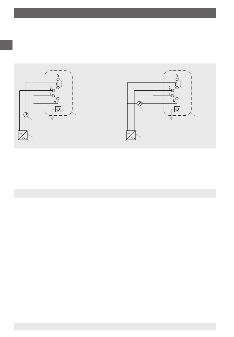
4 … 20 mA, 2-wire system RA≤(UB- 10 V) / 0.02 A with RAin Ohm and UBin Volt
0 … 20 mA, 3-wire system RA≤(UB- 10 V) / 0.02 A with RAin Ohm and UBin Volt
Effect of load % of span ≤0.1
Response time s approx. 1 (optional approx. 50 ms)
Output signal adjustment
Zero point, electrical% of span ± 15
Span, electrical% of span ± 30
Linearity % of span 2.5 (limit point calibration)
(including hysteresis) optional 1.6 (limit point calibration)
Permissible
Medium temperature°C +80 maximum
Ambient temperature°C -10 … +60 (optional LCD-display 0 … 50)
Compensated temp. range °C -10 … +60 (optional LCD-display 0 … 50)
Temperature coefficient in
compensated temp. range
Average TKon zero point≤0.4 % of span/10 K
Average TKon span≤0.4 % of span/10 K
LCD-display (optional)
Voltage loadDC V 3.5
Display3 ½-digit, height 12.7
Ambient temperature°C 0 … 50
Storage temperature°C -10 … +80
Wiring Terminal box (screw terminals up tu 2.5 mm²)
Wiring protection Protected against reverse polarity and overvoltage
EMC (electro-magnetic
compatibility)
Interference emission per EN 50 081 - 1 (March 93) and EN 50 081 - 2 (March 94),
Interference immunity per EN 50 082 - 2 (March 95)
Ingress protection IP 54 (optional IP 65) according EN 60 529 / IEC 529
Weight kg approx. 1.3
2279453 08/2009 GB/D/F
WIKA Operating Instructions Differential Pressure Transmitter DELTA-trans 9
8. Technical data

GB
8. Technical data
Additional or deviating technical data
Pressure ranges bar 0 ... 0.25 to 0 ... 10
Output signal 4 ... 20 mA, 2-wire or 0 ... 20 mA, 3-wire current limit I < 32 mA
Permissible ambient
temperature
°C -10 … +70
EMC (electro-magnetic
compatibility)
Interference emission per EN 50 081-1 (March 93) and
EN 50 081-2 (March 94),
interference immunity per EN 50 082-2 (March 95)
ESD kV ± 8 contact discharge IEC 1000-4-2
Electromagnetic fields V/m 10 80 % AM, 1 kHz, 0.01 ... 1000 MHz IEC 1000-4-3
Burst kV ± 2 coupling clamp IEC 1000-4-4
Conducted HF-disturbance V 3 80 % AM, 1 kHz, 0.01 ... 100 MHz IEC 1000-4-6
Surge kV ± 0.5 symmetrically IEC 1000-4-5
kV ± 1 asymmetrically, R i = 42 Ohm
kV ± 1 symmetrically
kV ± 2 asymmetrically, R i = 42 Ohm, with surge
protection only e.g. model MM-DS/x-
NFE(L), firm Dehn & Söhne or equivalent
Conducted NF-disturbance Veff 3 0.05 ... 10 kHz IEC 945
Vibration test Fc
2 ... 25 Hz, +/- 1.6 mm % < 2.5 error IEC 68-2-6
25 ... 100 Hz, 4 g % < 2.5 error
Approval German Lloyd (optional)
2279453 08/2009 GB/D/F
WIKA Operating Instructions Differential Pressure Transmitter DELTA-trans
10

GB
9. Service and maintenance
2279453 08/2009 GB/D/F
WIKA Operating Instructions Differential Pressure Transmitter DELTA-trans 11
9. Service and maintenance
Always open isolating devices gently, as abrupt opening may generate sudden
pressure surges that may damage the transmitter.
The pressure transmitters require no maintenance or servicing and will give very
long service when handled and operated correctly. It may well be necessary
to check and readjust the zero point periodically. This depends on the working
conditions.
To check zero point
In general, the zero point should be checked and adjusted with the instru-
ment in the unpressurised state.
With differential pressure transmitters the zero point should be checked and
adjusted by opening the pressure equalising valve while under a static load.
The plug screw (NP), found on the top of the case, must be unscrewed to
correct the zero point of the pressure transmitter. The zero point potentiometer
can then be readjusted using a small screwdriver:
turning anticlockwise ⇒ reduces the output signal
turning clockwise ⇒ increases the output signal
To check measuring span
Checking and adjusting the measuring span is a little more complex and has
to be carried out when the pressure transmitter is under pressure, up to the
upper limit of the effective range.
A sufficiently-accurate pressure standard is necessary as a reference.
Only when it is necessary to correct the measuring span should the plug
screw (SP) in the top of the case be unscrewed, and the measuring span
potentiometer can then be readjusted using a small screwdriver:
turning anticlockwise ⇒ reduces the output signal
turning clockwise ⇒ increases the output signal
Once this has been done, the zero point must be checked again and, if neces-
sary, the zero point must be readjusted. This procedure should be repeated
until the zero point and span are calibrated.

GB
9. Service and maintenance / 10. Special instructions ...
SP potentiometer for span
NP potentiometer for zero point
2158991.01
Measuring differential
pressure again
release
valve
actuate
Differential pres-
sure drops to zero
2279453 08/2009 GB/D/F
WIKA Operating Instructions Differential Pressure Transmitter DELTA-trans
12
10. Special instructions for integrated pressure equalising valve or
4-way valve manifold
10.1 Integrated pressure equalising valve
For zero point control on working
processes. Offset errors can be adjusted
using the zero point potentiometer (see
Chapter 9. Service and Maintenance)
Principle of operation
When the button is pressed, the
separation between the measuring chambers is released. The pressure
is thus equalised in both chambers, and the differential pressure is zero.
Releasing the button separates the chambers again and the current differen-
tial pressure is measured.
Position of potentiometers in the electronics case

GB
10. Special instructions for integrated pressure equalising valve ...
Gauge valve,
high pressure
j-
side
Gauge valve, low
pressure
i-
side
Pressure equa-
lising valve
Valve for purging
or bleeding air
2279453 08/2009 GB/D/F
WIKA Operating Instructions Differential Pressure Transmitter DELTA-trans 13
10.2 Four-way valve manifold
Functions
Shut off j- and i-process line for removing the transmitter from working
processes
Pressure equalisation for zero point control on working processes
Process line air bleeding
10.2.1 Handling instructions
Sequence of operations to start measuring
1. Open pressure equalising valve (middle
valve)
2. Open shut-off valve for the minus media
chamber (i) left valve
3. Open shut-off valve for the plus media
chamber (j) right valve
4. Close pressure equalising valve
Sequence of operations at the end of the
measuring operation (also for partial shut-
down of the system)
1. Open pressure equalising valve
2. Close shut-off valve for the minus media chamber (i)
3. Close shut-off valve for the plus media chamber (j)
Sequence of operations to remove the transmitter during working processes
1. Open pressure equalising valve
2. Close shut-off valve for the minus media chamber (i)
3. Close shut-off valve for the plus media chamber (j)
4. Open valve for purging or air bleeding

GB
11. Storage / 12. Troubleshooting
Defect Possible reason Remedy
No signal output Failure of power supply or wiring
interrupted
Check power supply and wiring;
replace defective components
Transmitter miswired Check wiring; if necessary
rectify it
No pressure Check tailpipes
Electronic defect through incor-
rect supply voltage or external
voltage
Return transmitter to manufac-
turer for repair
Steady signal, despite pressure
changes
Pressure entry blocked Check tailpipes and pressure
entry bore, if necessary clean it
carefully
Electronic defect through incor-
rect supply voltage or external
voltage
Return transmitter to manufac-
turer for repair
Transmitter failure through
overpressurisation
Return transmitter to manufac-
turer for repair
Steady and excessively high
signal, despite pressure
changes
Electronic defect through incor-
rect supply voltage or external
voltage
Return transmitter to manufac-
turer for repair
Full span reading too low Supply voltage too low Adjust supply voltage
Load impedance too high Consider permissible max. load
Span adjustment made incor-
rectly
Re-calibrate transmitter
Zero signal too low Zero adjustment made incor-
rectly
Re-calibrate transmitter
Zero signal too high Zero adjustment made incor-
rectly
Re-calibrate transmitter
Transmitter over-pressurised Return transmitter to manufac-
turer for repair
Non-linear signal output despite
correct zero adjustment
Transmitter over-pressurised Return transmitter to manufac-
turer for repair
2279453 08/2009 GB/D/F
WIKA Operating Instructions Differential Pressure Transmitter DELTA-trans
14
11. Storage
Before installation, in order to prevent damage to the transmitters, the following
points should be observed:
The pressure transmitter should remain in its original packing until installation.
After taking out the transmitter (e.g. for tests), reuse the original packaging
material.
The storage temperature should not be less than -20 °C or more than +60 °C.
Transmitters should be protected against dust and humidity.
12. Troubleshooting

GB
13. Maintenance and servicing/cleaning ... 15. Disposal
2279453 08/2009 GB/D/F
WIKA Operating Instructions Differential Pressure Transmitter DELTA-trans 15
13. Maintenance and servicing/cleaning
The instruments require no maintenance or servicing and will give very long
service when handled and operated properly.
The indicator and switching function should be checked once or twice every
12 months. The instrument must be disconnected from the process before
being checked using pressure testing equipment.
The instruments should be cleaned with a damp cloth, moistened with soap
solution. Ensure that all the parts are dry before the power is switched on again.
Any residual pressure medium contained in the pressure element may be
hazardous or toxic. This should be taken into account when handling and
storing pressure gauges which have been removed.
14. Repairs
Repairs are only to be carried out by the manufacturer or appropriately trained
personnel.
For further details see the Data Sheet for the respective basic gauge PV 17.18.
15. Disposal
Dispose of instrument components and packaging materials in accordance
with the respective waste treatment and disposal regulations of the region or
country to which the instrument is supplied.

GB
2279453 08/2009 GB/D/F
WIKA Operating Instructions Differential Pressure Transmitter DELTA-trans
16

D
Inhalt
1. Sicherheitshinweise 18
2. Funktionsprinzip 18
3. Montagehinweise 19
4. Montage und Inbetriebnahme 20
5 Messanordnung 21
6. Elektrischer Anschluss 21
7. Ausführung mit LCD-Anzeige (Option) 22
8. Technische Daten 23
9. Bedienung und Wartung 25
10. Besonderheiten bei integriertem Druckausgleichsventi oder
Vierfach-Ventilblock
26
11. Lagerung 28
12. Maßnahmen bei Störungen 28
13. Wartung und Reinigung 29
14. Reparaturen 29
15. Entsorgung 29
2279453 08/2009 GB/D/F
WIKA Betriebsanleitung Differenzdruck-Messumformer DELTA-trans 17
Inhalt
Warnung!
Dieses Symbol warnt Sie vor Handlungen, die Schäden an
Personen oder am Gerät verursachen können.

D
1. Sicherheitshinweise / 2. Funktionsprinzip
2155079.01
2279453 08/2009 GB/D/F
WIKA Betriebsanleitung Differenzdruck-Messumformer DELTA-trans
18
1. Sicherheitshinweise
Beachten Sie unbedingt bei Montage, Inbetriebnahme und
Betrieb dieser Geräte die entsprechenden nationalen Sicher
heitsvorschriften (z. B. VDE 0100 / EN 60 079-14 / EN 837-2).
Alle Arbeiten dürfen nur im spannungslosen Zustand erfolgen
Bei Nichtbeachten der entsprechenden Vorschriften können schwere Körper-
verletzungen und / oder Sachschäden auftreten
Nur entsprechend qualifiziertes Personal darf an diesen Geräten arbeiten
2. Funktionsprinzip
Der Differenzdruck-Messumformer besteht im Wesentlichen aus den Funk-
tionsgruppen mechanisches Messsystem (1) mit federelastischem Messglied
(2), magnetfeldabhängiger Sensor (3) mit Signalverarbeitungsplatine (4) und
Gehäuse mit den Anschlussteilen für die Elektronik.
Ein mit dem Messglied fest gekop-
pelter Magnet (5) beeinflusst das
elektromagnetische Feld des HALL-
Sensors.
Das dabei entstehende Signal wird
durch die Signalverarbeitungsplatine
in ein normiertes Stromausgangssi-
gnal verstärkt.
Zur Nachkalibrierung können
Nullpunkt und Spanne über leicht
zugängliche Potentiometer (6) einge-
stellt werden.
Montage nach angebrachten
Symbolen, jhoher Druck und i
niedriger Druck

D
3. Montagehinweise
2279453 08/2009 GB/D/F
WIKA Betriebsanleitung Differenzdruck-Messumformer DELTA-trans 19
3. Montagehinweise
Montageanordnung
Der Druckmessumformer muss erschütterungsfrei befestigt und betrieben
werden. Es empfiehlt sich, zwischen Druckentnahmestelle und Druck-
messumformer eine Absperrvorrichtung zwischenzuschalten, die einen
Austausch des Messgerätes und eine Nullpunktkontrolle bei laufender
Anlage ermöglicht.
Prüfanschluss
Bei bestimmten Anwendungsfällen (z. B. Dampfkessel) müssen die Absperr-
armaturen einen Prüfanschluss besitzen, damit der Druckmessumformer
ohne Ausbau überprüft werden kann.
Messgerätebefestigung
Ist die Leitung zum Druckmessumformer für eine erschütterungsfreie Anbrin-
gung nicht stabil genug, so ist die Befestigung über die Befestigungslaschen
zur Wandmontage vorzunehmen.
Temperaturbelastung
Die Anbringung des Druckmessumformers ist so auszuführen, dass die
zulässigen Betriebstemperaturen (Umgebung, Messstoff), auch unter
Berücksichtigung des Einflusses von Konvektion und Wärmestrahlung,
weder unter noch überschritten werden. Druckmessumformer und gegebe-
nenfalls angebaute Absperrarmaturen sind z. B. durch ausreichend lange
Messleitungen zu schützen. Der Temperatureinfluss auf die Messgenauigkeit
ist zu beachten.
Schutz der Messglieder vor Überlastung
Unterliegt der Messstoff schnellen Druckänderungen oder ist mit Druckstö-
ßen zu rechnen, so dürfen diese nicht direkt auf das Messglied einwirken.
Die Druckstöße müssen in ihrer Wirkung gedämpft werden, z. B. durch
Einbau einer Drosselstrecke (Verringerung des Querschnittes im Druckkanal)
oder durch Vorschaltung einer einstellbaren Drosselvorrichtung.
Druckentnahmestutzen
Der Druckentnahmestutzen soll mit einer genügend großen Bohrung (≥6 mm)
möglichst über ein Absperrorgan so angeordnet werden, dass die Druckent-
nahme nicht durch eine Strömung des Messstoffes verfälscht wird. Die Mess-
leitung zwischen Druckentnahmestutzen und Druckmessumformer soll zur
Vermeidung von Verstopfung und Verzögerungen bei der Druckübertragung
einen genügend großen Innendurchmesser besitzen und ohne scharfe
Krümmung sein. Ihre Verlegung mit einer stetigen Neigung von ca. 1:15 ist zu
empfehlen.

D
3. Montagehinweise / 4. Montage und Inbetriebnahme
2279453 08/2009 GB/D/F
WIKA Betriebsanleitung Differenzdruck-Messumformer DELTA-trans20
Messleitung
Die Messleitung ist so auszuführen und zu montieren, dass sie die auftre-
tenden Belastungen durch Dehnung, Schwingung und Wärmeeinwirkung
aufnehmen kann. Bei Gasen als Messstoff ist an der tiefsten Stelle eine
Entwässerung, bei flüssigen Messstoffen an der höchsten Stelle eine Entlüf-
tung vorzusehen.
4. Montage und Inbetriebnahme
Zur Abdichtung der Anschlüsse sind Flachdichtungen, Dichtlinsen oder WIKA-
Profildichtungen einzusetzen.
Ist der Druckmessumformer tiefer als der Druckentnahmestutzen angeordnet,
dann muss die Messleitung vor dem Anschließen gut durchgespült werden, um
Fremdkörper zu beseitigen.
Nach Herstellen der Druckverbindung und der elektrischen Anschlüsse sind die
Druckmessumformer sofort betriebsbereit.
Vor dem Ausbau des Druckmessumformers ist das Messglied drucklos zu
machen. Gegebenenfalls muss die Messleitung entspannt werden.
Messstoffreste in ausgebauten Druckmessumformern können zur Gefährdung
von Menschen, Umwelt und Einrichtung führen. Ausreichende Vorsichtsmaß-
nahmen sind zu ergreifen.
This manual suits for next models
1
Table of contents
Languages:
Other WIKA Transmitter manuals
Popular Transmitter manuals by other brands

TeknikSat Satellite Systems
TeknikSat Satellite Systems TPF 11-2 user guide

Williams Sound
Williams Sound Hearing Helper T800 Manual and user guide

Auto Mate
Auto Mate 7142A quick start guide

Crestron
Crestron DM-TX-401-C quick start guide

Intelix
Intelix AvoCat AVO-SVA2-WP-F Series installation manual

Audio Technica
Audio Technica ATW-T1006 Installation and operation